IHDT6NB1Cellular Transceiver Module
Motorola Mobility LLC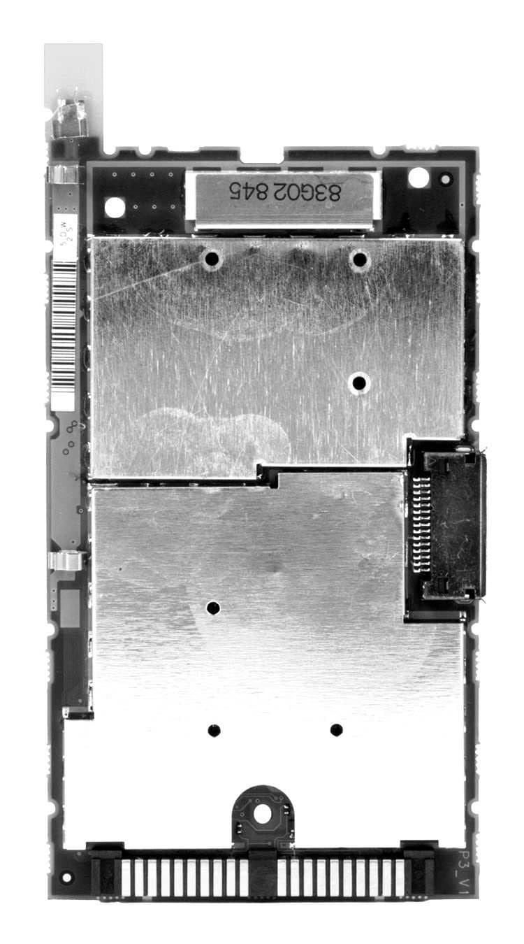
Click to zoom
Application Details
- Equipment Class
- PCE - PCS Licensed Transmitter held to ear
- Date of Grant
- Jul 07, 1999
- Application Purpose
- Original Equipment
- Date of Application
- Mar 23, 1999
- Equipment Note
- Cellular Transceiver Module
- Frequency Range
- 1851.25000000 - 1908.75000000
- Company
- Motorola Mobility LLC
- Country
- United States
Documents & Files
Document Text
Text extracted from the exhibit documents filed with the FCC. Open a document above to read the original.
Users Manual
Satellite Series TM 9500 Portable Phone User’s Guide INDY.book Page 1 Thursday, August 20, 1998 8:57 AM Personal Communications Sector 600 North U.S. Highway 45 Libertyville, Illinois 60048 , , VibraCall, andTurboDial are registered trademarks of Motorola, Inc. Iridium, the Iridium logo, and Iridium World Service are registered trademarks and/or service marks of Iridium IP LLC. ©1998 Motorola, Inc. Printed in U.S.A. INDY.book Page 2 Thursday, August 20, 1998 8:57 AM iii Contents Welcome! Guide Overview . . . . . . . . . . . . . . . . . . . . . . . . . . . . . . . . . . . . . . 10 Technology Overview . . . . . . . . . . . . . . . . . . . . . . . . . . . . . . . . . . 13 Features Overview . . . . . . . . . . . . . . . . . . . . . . . . . . . . . . . . . . . . 16 Phone Overview . . . . . . . . . . . . . . . . . . . . . . . . . . . . . . . . . . . . . . 17 The Indicators . . . . . . . . . . . . . . . . . . . . . . . . . . . . . . . . . . . . . . . . 19 Package Contents and Options . . . . . . . . . . . . . . . . . . . . . . . . . . 22 Getting Started Battery Information . . . . . . . . . . . . . . . . . . . . . . . . . . . . . . . . . . . . 26 Removing the Battery Covers . . . . . . . . . . . . . . . . . . . . . . . . . . . . 27 Installing the Battery . . . . . . . . . . . . . . . . . . . . . . . . . . . . . . . . . . . 28 Checking the Battery . . . . . . . . . . . . . . . . . . . . . . . . . . . . . . . . . . 30 Charging the Battery . . . . . . . . . . . . . . . . . . . . . . . . . . . . . . . . . . . 32 What Is a SIM Card? . . . . . . . . . . . . . . . . . . . . . . . . . . . . . . . . . . . 34 Installing the SIM Card . . . . . . . . . . . . . . . . . . . . . . . . . . . . . . . . . 35 What is a Cellular Cassette? . . . . . . . . . . . . . . . . . . . . . . . . . . . . . 36 Installing the Cellular Cassette . . . . . . . . . . . . . . . . . . . . . . . . . . . 37 Using Your Phone Feature Overview . . . . . . . . . . . . . . . . . . . . . . . . . . . . . . . . . . . . . 40 Powering Up the Phone . . . . . . . . . . . . . . . . . . . . . . . . . . . . . . . . 41 Placing Calls . . . . . . . . . . . . . . . . . . . . . . . . . . . . . . . . . . . . . . . . . 43 Receiving Calls . . . . . . . . . . . . . . . . . . . . . . . . . . . . . . . . . . . . . . . 47 Ending a Call . . . . . . . . . . . . . . . . . . . . . . . . . . . . . . . . . . . . . . . . 49 Using Call Waiting . . . . . . . . . . . . . . . . . . . . . . . . . . . . . . . . . . . . . 50 Placing a Call on Hold . . . . . . . . . . . . . . . . . . . . . . . . . . . . . . . . . 51 + Muting a Call . . . . . . . . . . . . . . . . . . . . . . . . . . . . . . . . . . . . . . 53 Sending a Phone Flash . . . . . . . . . . . . . . . . . . . . . . . . . . . . . . . . . 54 Basic Phone Setup . . . . . . . . . . . . . . . . . . . . . . . . . . . . . . . . . . . . 55 Using the Menus Using the Options Menus . . . . . . . . . . . . . . . . . . . . . . . . . . . . . . . 58 + Using the Quick Access Menu . . . . . . . . . . . . . . . . . . . . . . . . 61 Using The In-Call Menu . . . . . . . . . . . . . . . . . . . . . . . . . . . . . . . . 63 Managing the Phone Book What’s on the Menu? . . . . . . . . . . . . . . . . . . . . . . . . . . . . . . . . . . . 66 Feature Overview . . . . . . . . . . . . . . . . . . . . . . . . . . . . . . . . . . . . . 67 Organizing Your Phone Book . . . . . . . . . . . . . . . . . . . . . . . . . . . . 68 INDY.book Page iii Thursday, August 20, 1998 8:57 AM iv Storing Names and Numbers . . . . . . . . . . . . . . . . . . . . . . . . . . . .70 Entering Names . . . . . . . . . . . . . . . . . . . . . . . . . . . . . . . . . . . . . .72 Using Pauses in Numbers . . . . . . . . . . . . . . . . . . . . . . . . . . . . . .74 + Using Phone Number Prefixes . . . . . . . . . . . . . . . . . . . . . . . . .75 Recalling Entries . . . . . . . . . . . . . . . . . . . . . . . . . . . . . . . . . . . . . .76 Calling, Modifying, or Erasing an Entry . . . . . . . . . . . . . . . . . . . . .78 + Checking Phone Book Capacity . . . . . . . . . . . . . . . . . . . . . . .79 + Preventing Access to the Phone Book . . . . . . . . . . . . . . . . . . .80 + Restricting Phone Use . . . . . . . . . . . . . . . . . . . . . . . . . . . . . . .81 Viewing the Last Ten Numbers Dialed . . . . . . . . . . . . . . . . . . . . .85 Viewing and Modifying Phone Numbers . . . . . . . . . . . . . . . . . . . .86 + One-Touch Dialing . . . . . . . . . . . . . . . . . . . . . . . . . . . . . . . . . .88 Using Calling Features What’s on the Menu? . . . . . . . . . . . . . . . . . . . . . . . . . . . . . . . . . . .90 Feature Overview . . . . . . . . . . . . . . . . . . . . . . . . . . . . . . . . . . . . .91 + Showing the Battery Meter . . . . . . . . . . . . . . . . . . . . . . . . . . . .92 + Showing Signal Strength . . . . . . . . . . . . . . . . . . . . . . . . . . . . .93 + Deactivating Pending Call Drop Signal . . . . . . . . . . . . . . . . . .94 Using Call Forwarding . . . . . . . . . . . . . . . . . . . . . . . . . . . . . . . . .95 + Activating Call Waiting . . . . . . . . . . . . . . . . . . . . . . . . . . . . . .100 Restricting Calls . . . . . . . . . . . . . . . . . . . . . . . . . . . . . . . . . . . . .101 Using Message Services What’s on the Menu? . . . . . . . . . . . . . . . . . . . . . . . . . . . . . . . . . .106 Feature Overview . . . . . . . . . . . . . . . . . . . . . . . . . . . . . . . . . . . .107 + Checking Your Voicemail . . . . . . . . . . . . . . . . . . . . . . . . . . . .108 + Storing Your Voicemail Number . . . . . . . . . . . . . . . . . . . . . . .109 Managing Your Messages . . . . . . . . . . . . . . . . . . . . . . . . . . . . .110 Accessing Messages . . . . . . . . . . . . . . . . . . . . . . . . . . . . . . . . .112 Customizing Phone Features What’s on the Menu? . . . . . . . . . . . . . . . . . . . . . . . . . . . . . . . . . .116 Feature Overview . . . . . . . . . . . . . . . . . . . . . . . . . . . . . . . . . . . .117 Adjusting Your…
Text truncated - open the document above for the full version.
Attestation Statements
APPLICANT: MOTOROLA, INC.FCC ID : IHDT6NB1 EXHIBIT 1 STATEMENT OF CERTIFICATION The technical data supplied with this application, having been taken under my supervision, is hereby duly certified. The following is a statement of my qualifications: BSEE 1980 University of Louisville, Louisville, KY MSEE 1981 University of Louisville, Louisville, KY 18 years experience in RF communications product design and development. SIGNATURE:____________________ NAME: Owen B. Thompson, Jr. DATE: 4/1/99 POSITION: Senior Engineer I hereby certify that the above application was prepared under my direction and that, to the best of my knowledge and belief, the facts set forth in the application and accompanying technical data are true and correct. SIGNATURE:____________________ NAME: Ron Young DATE: 4/1/99 POSITION: Engineering Project Leader
ID Label/Location Info
APPLICANT: MOTOROLA, INC.FCC ID: IHDT6NB1 EXHIBIT 10 FCC IDENTIFICATION (NAMEPLATE) INFORMATION The Equipment ID label above is representative (in size and in showing the FCC Identifier as it will appear) of the actual label that will appear on the equipment when in production. Its location is shown in Exhibit 11-2. FCC ID: IHDT6NB1 SCALE 2:1
Internal Photos
APPLICANT: MOTOROLA, INC.FCC ID: IHDT6NB1 EXHIBIT 11-5 APPLICANT: MOTOROLA, INC.FCC ID: IHDT6NB1 EXHIBIT 11-6
Operational Description
APPLICANT: MOTOROLA, INC.FCC ID : IHDT6NB1 EXHIBIT 2-1 GENERAL INFORMATION 1. Production Plans---Pursuant 2.983 (c) Quantity production is planned. 2. Application References---Pursuant 2.1061 Reference is made to the following Motorola "Application References" on file with the Commission: None 3.Data Submittal Procedure: Data is supplied in accordance with Part 2, Sub-part J of the Commission’s rules. Standard used on measurements supplied are J-STD-008. 4.Similar to "Currently Type Accepted Transmitter Type(s)" FCC ID: IHDT6XB1 This transceiver is based on the same design as FCC ID: IHDT6YN1, (type acceptance granted IHDT6YN1). The primary difference is that this device has been repackaged mechanically to be inserted into an IRIDIUM communications system handset (see Exhibits 7 and 11) and can function as a self contained RF transceiver module to provide alternative terrestrial cellular service to the handset. All power and user interface functions (transmit and receive audio, keypad operations and display) are provided by the IRIDIUM handset 5.Report of measurements pertaining to types of emission, frequency range, maximum output power and modulation techniques for Digital Mode Operation (per paragraphs 31 and 32 of the Report and Order in FCC GEN. Docket No. 87-390). APPLICANT: MOTOROLA, INC.FCC ID : IHDT6NB1 EXHIBIT 2-2 A. Types of emission The equipment is designed to provide emissions consistent with emission designator 1M25F9W as determined as explained in paragraph 6 of this exhibit. Reference is also made to J-STD-008. Actual measurements of Occupied Bandwidth for the Digital CDMA Mode are shown in Exhibit 9B. Spurious Emissions (Conducted and Radiated) reported in Exhibits 9C1, 9C2, and 9D are the worst (highest level) of Digital and Analog Modes. B. Frequency range The frequency range of the equipment is the Domestic Public Personal Communications Service bands, 1850 - 1910 MHz (transmit) and 1930 - 1990 (receive) MHz. Frequency Stability versus Temperature and Voltage measurements are shown in Exhibits 9E and 9F. This equipment uses Automatic Frequency Control (AFC) to lock to within ± 150 Hz of the received frequency from the Land Station system for Digital Mode. Also refer to Exhibit 8A. C. Maximum output power In Digital CDMA Mode, the maximum radio frequency power allowed per the standard ranges from 0.2 Watts to 1.0 Watt. The mobile maximum output power during a power control group is within the specified limits and is controlled by commands from a land station system. The maximum nominal power setting for this equipment is 0.280 Watts. R. F. Output Power measurement results are shown in Exhibit 9A. D. Modulation techniques Modulation is OQPSK (Offset Quaternary Phase Shift Keying). Reference is made to the J-STD-008, Section 2.1.3. Exhibits 8C and 8D further discuss details of the modulating circuitry. Exhibit 9B show the results of modulation related testing. APPLICANT: MOTOROLA, INC.FCC ID : IHDT6NB1 EXHIBIT 2-3 6.Determination of Emission Designator for Digital (CDMA) Operation (per Part 2 - Subpart C of the commission’s rules) A. Emission, modulation and transmission characteristics (per section 2.201) a. First Symbol - Type of modulation of the main carrier. The main carrier is Offset Quaternary Phase Shift Keyed (OQPSK) and has both amplitude and angle modulation characteristics during the digital mode of operation. OQPSK in and of itself does not necessarily produce amplitude modulation characteristics, however, the In-Phase (I) channel and the Quadrature (Q) channel modulating signals are filtered by a 47 tap FIR filter specified in TIA/EIA IS-95-A, section 6 before being applied to a quadrature modulator. The filtering produces amplitude variation on the main carrier. In addition, the carrier is gated on and off at a rate determined by the transmission data rate as specified in TIA/EIA IS-95-A, section 6. Therefore, the main carrier is not a constant envelope signal, but is both amplitude and angle-modulated. This corresponds to the symbol D, defined as “Emissions in which the main carrier is amplitude and angle-modulated either simultaneously or in a preestablished sequence.” b. Second Symbol - nature of signal(s) modulating the main carrier. One Digital Signal representing sampled, quantized voice or other audio information or data modulates the main carrier using direct sequence CDMA techniques during the digital mode of operation. This corresponds to symbol 1, defined as “A single channel containing quantized or digital information without the use of a modulating sub-carrier, excluding time division multiplex.” c. Third symbol - Type of information to be transmitted. The information transmitted in the digital mode of operation is a combination of data transmission (command data) and telephony (sampled quantized voice or other audio signals). APPLICANT: MOTOROLA, INC.FCC ID : IHDT6NB1 EXHIBIT 2-4 This corresponds to symbol W, defined as “combination of above” which would be the combination of symbol D, “Data transmission, telemetry, telecommand,” and symbol E, “Telephony (including sound broadcasting).” B. Bandwidths (per section 2.202) Bandwidth is primarily determined by a 47 tap FIR filter used to filter the I channel and Q channel modulating signals. Per TIA/ EIA IS-95-A Section 6.1.3.1.10, the filter is defined to have a one-sided 1.5 dB ripple bandwidth of 590 kHz minimum and a 40dB minimum stopband at 740 kHz maximum. Computer simulations show that the occupied bandwidth as defined in paragraph 2.202(a) is 1.25MHz. Based on these considerations, the bandwidth used is 1.25 MHz. Converting this result to the format indicated in paragraph 2.202(a), yields 1M25. The resulting complete emission designator for the digital mode of operation is then 1M25F9W.
Parts List/Tune Up Info
APPLICANT: MOTOROLA, INC.FCC ID : IHDT6NB1 EXHIBIT 8 TRANSCEIVER ADJUSTMENTS TRANSCEIVER ADJUSTMENTS/TUNE-UP PROCEDURE There are no user accessible adjustments or tuning in this portable cellular transceiver. All necessary adjustments and tuning are performed during manufacture of the product. Any adjustments or tuning after service or repair are done as part of that process as special equipment is required to perform such adjustments.
RF Exposure Info
APPLICANT: MOTOROLA INC.FCC ID: IHDT6NB1 Page 1 of 1 Radiofrequency Energy Exposure Evaluation Statement. Motorola, Inc., Personal Communications Sector, hereby certifies that, when used as stated in the operating instructions supplied, this Wideband PCS Portable Transceiver, FCC ID: IHDT6NB1, complies with the FCC’s Radiofrequency energy exposure limits for General Population/Uncontrolled environment, per FCC Rule 47CFR2.1093.
RF Exposure Info
P P a a g g e e 1 1 May 11, 1999 SAR Test Report for Motorola portable cellular phone (FCC ID IHDT6NB1). Prepared by: Paul Moller, Principal Staff Engineer Motorola Personal Communications Sector Product Safety Laboratory Libertyville, Illinois Contents 1) Introduction 2) Applicable Regulations 3) Description of Test Sample 4) Description of Motorola SAR Test Facility 5) Test Sample Conditions 6) Method of Measurement 7) Measurement Uncertainty 8) SAR Test Results 9) Summary Appendix A: Included data Appendix B: Measurement Probe Calibration Certificate Appendix C: Printout from the Dasy measurement system validation test Appendix D: Dasy Users Manual (first page) P P a a g g e e 2 2 1. Introduction The Motorola Personal Communications Sector Product Safety Laboratory has performed measurements of the maximum potential exposure to the user of portable cellular phone module, FCC ID IHDT6NB1. The Specific Absorption Rate (SAR) of this product was measured. This report details the test setup and equipment as well as the results of those tests. 2. Applicable Regulations Federal Communications Commission rule §2.1093(d)(2), the ANSI/IEEE C95.1 1992 and the NCRP Report Number 86 specify the maximum exposure limit of 1.6 W/kg as averaged over any 1 gram of tissue for portable devices being used within 20cm of the user in the uncontrolled environment. 3. Description of Test Sample A prototype unit serial number 120399-13A was measured. This unit is identical in physical construction, maximum radiated power levels and antenna structure to units that will be in production. The portable cellular phone is a transceiver module that has been designed to be mechanically inserted into an IRIDIUM communications system handset, and can function as a self contained RF transceiver module to provide alternative terrestrial cellular service to the IRIDIUM handset. A picture of the module is shown as figure 1. It transmits in the frequency range of 1850 to 1910 MHz using CDMA (digital) mode only. The reported maximum peak transmit EIRP for this test unit is 0.39 Watts as defined in FCC Rule §24.232. The unit was tested at its maximum transmitter power, which is nominally a peak conducted power of 0.25 Watt. Figure 1. Transceiver Module, FCC ID: IHDT6NB1 The module is equipped with a telescoping antenna that serves as both a receive and transmit antenna. The antenna has a retracted and an extended operating position and is shown installed in the IRIDIUM handset as figures 2 and 3 respectively. Since the module inserts into the back side of the IRIDIUM communications system handset, a view of the back of the complete package is shown in figure 4. Note that in figure 4 the IRIDIUM antenna is in its P P a a g g e e 3 3 stowed, or unused, position. Figure 5 is the same as figure 4 only with the IRIDIUM antenna removed and a dust cover inserted in the IRIDIUM handset phone’s antenna socket. Figure 2. IRIDIUM handset with module antenna retracted Figure 3. IRIDIUM handset with module antenna extended P P a a g g e e 4 4 Figure 4. IRIDIUM handset and antenna, with module antenna extended Figure 5. IRIDIUM handset (antenna removed), with module antenna extended Figures 6 and 7 show the test unit as it is placed onto the phantom head with the module's antenna in the retracted and extended positions respectively. For the purposes of the actual SAR tests the Motorola phantom head is tilted on its side by 90 degrees so that a vertically oriented measurement probe can easily scan an area where the phone is in close contact with the phantom and the SAR will be the highest. P P a a g g e e 5 5 Figure 6. Test position with antenna retracted P P a a g g e e 6 6 Figure 7. Test position with antenna extended 4. SAR Test Facility The Motorola test facility utilized for the SAR testing of this product is the Personal Communications Sector Product Safety Laboratory, in Libertyville Illinois. The laboratory utilizes a Dosimetric Assessment System (Dasy™) SAR measurement system manufactured by Schmid & Partner Engineering AG (SPEAG™), of Zurich Switzerland. This system utilizes a computer controlled six axis robot to move a measurement probe to measure the SAR. A photo of the Dasy system with the Motorola phantom is shown in figure 8. Probe serial number 1005 was used for the measurements. It was calibrated at SPEAG™, and has a calibration date June 12, 1998. A copy of the calibration certificate is included as appendix B. Dipole Validation Kit type D1800V2, serial number 226 was used to validate the system accuracy. The validation SAR value is 39.9 mW/g normalized to 1 Watt, and the Dasy system used for the test phone measured 40.4 mW/g normalized to 1 Watt. This is within the required accuracy, and thus the measured SAR values are considered correct. See appendix C for printout of the validation test from the Dasy measurement system. The measurement methodology is described in IEEE Transactions on Vehicular Technology, vol. 44, no. 3, August 1995, titled Electromagnetic Energy Exposure of Simulated users of Portable Cellular Telephones. The Dasy system is P P a a g g e e 7 7 operated per the instructions in the Dasy Users Manual. A copy of the title page of this manual is included as appendix D. The entire manual is available directly from SPEAG. Figure 8. Motorola's SAR Measurement System 5. Test Sample Conditions For the purposes of these tests the subject phone and module was positioned on the measurement phantom per the instructions in the Motorola users manual. SAR was measured with the module’s antenna in both the retracted and extended positions. The position used for the tests is the 3-point contact position. In this position the test sample contacts the phantom’s ear and cheek and is positioned with a repeatability of better than ±6%. Since the antenna is not located on the center of the phone, the SAR was measured with the phone on both the left and right side talk positions (See figures 6 and 7). Due to…
Text truncated - open the document above for the full version.
RF Exposure Info
P P a a g g e e 1 1 June 10, 1999 Supplement to SAR Test Report for Motorola portable cellular phone (FCC ID IHDT6NB1). Prepared by: Paul Moller, Principal Staff Engineer Motorola Personal Communications Sector Product Safety Laboratory Libertyville, Illinois There were two questions asked about some of the data that was presented in the SAR Test Report for Motorola portable cellular phone (FCC ID IHDT6NB1) dated May 11, 1999. The following are the answers to those questions. 1) The Crest Factor is used to indicated the duty cycle of the incident wave form. The crest factor for a CDMA full rate signal should be 1.0. The crest factor on the original data was erroneously set to both 8 and 11. The following tables show that there is basically no difference in resultant SAR when the crest factor is set to 1.0 and the data is re-evaluated. Crest Factor set to 8 and 11 Left side head Right side head Antenna Antenna Antenna Antenna Conducted Channel Retracted Extended Retracted Extended Transmit Power 25 0.137 0.111 0.053 0.224 25.2 600 0.023 0.175 0.044 0.201 25.3 1175 0.048 0.010 0.041 0.068 25.0 Crest Factor set to 1.0 Left side head Right side head Antenna Antenna Antenna Antenna Conducted Channel Retracted Extended Retracted Extended Transmit Power 25 0.135 0.110 0.053 0.217 25.2 600 0.023 0.171 0.044 0.195 25.3 1175 0.048 0.010 0.041 0.068 25.0 A full data set output of two test conditions with the highest SAR values from the Dasy? measurement system is included as appendix A. P P a a g g e e 2 2 2) The Powerdrift is a measure of the change in dB of the electric field from just before to just after the SAR is measured at a location in the phantom called the “origin”. This location can be taught nearly anywhere in the phantom. Since the origin must be taught before the SAR measurement is taken, it is usually not possible to teach the origin at exactly the location of highest SAR in the phantom. Thus when the Powerdrift is measured it is usually done at a location where the SAR is somewhat lower than the highest measured 1g SAR. In the case of the test unit that was evaluated, FCC ID IHDT6NB1, the highest 1g SAR was found to be 0,22 mw/g, and the Powerdrift was measured about 2 cm away from the peak SAR location. The result is that there is some “noise” on the Powerdrift measurement due to the very low values being compared. The reported Powerdrifts for all measurements of this unit range from –2.4dB to +1.9dB. Even if the full –2.41dB Powerdrift were the actual change in test sample power out, the resultant SAR value would be well below the 1.6 mw/g limit. Additionally the test sample was found to have some drift in its conducted power output. This drift was found to be –0.9dB over 15 minutes, and –1.8dB over 30 minutes. Since the SAR measurement takes about 15 minutes, it can be concluded that the SAR at the beginning of the measurement was 0.9dB higher than is reported (since SAR is actually measured closer to the end of the measurement time). It is therefore reasonable to assume that the actual SAR values could have been as much as 0.9dB above the values reported by the measurement system. This would correspond to a maximum SAR value of 0.224 + 0.9dB = 0.276 W/Kg. P P a a g g e e 3 3 Appendix A The following pages are printouts from the Dasy measurement system of the data as indicated. SWF0240A S/N 120399-13A MOTO Left Phantom; Section; Position: ; Frequency: 1851 [MHz] Probe: ET3DV4 - SN1005 (DAE2); ConvF(5.10,5.10,5.10); Crest factor: 1.0; Brain 1900 MHz: σ = 1.71 [mho/m] ε r = 41.0 ρ = 1.00 [g/cm 3 ] Cube 5x5x7: SAR (1g): 0.135 [mW/g], SAR (10g): 0.0752 [mW/g], (Worst-case extrapolation) Coarse: Dx = 10.0, Dy = 10.0, Dz = 10.0 Powerdrift: -2.41 dB SAR Tot [mW/g] 7.65E-3 2.29E-2 3.82E-2 5.36E-2 6.88E-2 8.42E-2 9.94E-2 1.15E-1 1.30E-1 1.45E-1 03/11/99 Motorola, Inc. SWF0240A S/N 120399-13A MOTO Right Phantom; Section; Position: ; Frequency: 1851 [MHz] Probe: ET3DV4 - SN1005 (DAE2); ConvF(5.10,5.10,5.10); Crest factor: 1.0; Brain 1900 MHz: σ = 1.71 [mho/m] ε r = 41.0 ρ = 1.00 [g/cm 3 ] Cube 5x5x7: SAR (1g): 0.217 [mW/g], SAR (10g): 0.121 [mW/g], (Worst-case extrapolation) Coarse: Dx = 10.0, Dy = 10.0, Dz = 10.0 Powerdrift: 1.67 dB SAR Tot [mW/g] 9.55E-3 2.86E-2 4.78E-2 6.68E-2 8.59E-2 1.05E-1 1.24E-1 1.43E-1 1.62E-1 1.81E-1 03/12/99 Motorola, Inc.
Test Report
APPLICANT: MOTOROLA, INC.FCC ID : IHDT6NB1 EXHIBIT 12-1 MEASUREMENT TECHNIQUES 2.1051 Measurements Required: Conducted Spurious and Harmonic Emissions at Antenna Terminals Graph Attached EXHIBIT NO. 9C Definition - (as used herein) Spurious radiation is the radio frequency voltages or power generated within the equipment and appearing at the equipment’s output terminals when properly loaded with its characteristic non-radiating artificial load. Minimum Standard - Conducted spurious and harmonic emissions shall be attenuated 43 dB + 10Log10(the mean power output). In the range of frequencies between 1930 MHz and 1990 MHz, no spur shall exceed -81 dBm. Method of Measurement - The transmitter was modulated with OQPSK modulation using pseudo random data. The spectrum was scanned from the lowest frequency generated in the equipment to the tenth harmonic of the carrier. The level of the carrier and the various conducted spurious and harmonic frequencies were measured by means of a calibrated receiving system. The measurement of the allocation band edges were performed according to EXHIBIT 13 using 1% of the carrier necessary bandwidth and Brickwall filter techniques. APPLICANT: MOTOROLA, INC.FCC ID : IHDT6NB1 EXHIBIT 12-2 2.1053 Measurement Required: Radiated Spurious and Harmonic Emissions Graph Attached EXHIBIT NO. 9D Definition - Radiated spurious and harmonic emissions from the equipment at a frequency or frequencies which are outside an occupied band sufficient to insure transmission of information of required quality for the class of communications desired. The reduction in the level of these spurious emissions will not effect the quality of information being transmitted. Minimum Standard - Radiated spurious and harmonic emissions shall be attenuated 43 dB + 10Log10(the mean power output). Method of Measurement: Test Site - All testing reported herein was performed at the Motorola SSG open area test facility, located at 8201 E. McDowell Rd., Scottsdale, AZ. 85252. The OATS is located on the roof of the building and is built in accordance with ANSI C63.7. The facility has been found to be in compliance with the requirements of Section 2.948 of the FCC rules, per FCC letter 31040/SIT dated October 6, 1998. The facility has also been issued a Certificate of Accreditation through the National Voluntary Laboratory Accreditation Program (NVLAP) by NIST. This is under NVLAP Code: 100405-0 and is effective through September 30, 1999. Installation of Equipment The equipment under test is placed on the turntable in normal operation using the intended power source. A receiving antenna located 3 meters from the turntable picks up any signal radiated from the transmitter and its operating accessories. The antenna is adjustable in height from 1 to 4 meters and can be horizontally and vertically polarized. A HP 8566B spectrum analyzer system is used to scan the applicable frequency range to detect and measure any radiation picked up by the antenna. Preliminary radiated emission scans are conducted in a semi-anechoic enclosure in order to isolate emissions in an ambient free environment. APPLICANT: MOTOROLA, INC.FCC ID : IHDT6NB1 EXHIBIT 12- 3 Measurement Procedure The procedures of ANSI 63.4 are followed for radiated emission measurements. The equipment under test is adjusted to obtain peak readings of received signals wherever they occur in the spectrum by: 1. Rotating the transmitter under test. 2. Adjusting the antenna height and polarization. The testing procedure is repeated for both horizontal and vertical polarization of the receiving antenna. The radiated signal strength is derived from the received power levels and measured antenna factors. Also included in the field strength derivation are the cable losses and any other corrections for external attenuation and/or pre-amplification. The final measurement field strengths are recorded on the attached graphs. 2.995 Measurement Required: Frequency Stability Definition - The carrier frequency stability is the ability of the transmitter to maintain an assigned carrier frequency. Minimum Standard - The minimum frequency stability shall be +/-150Hz at any time during closed loop operation. Method of Measurement - Frequency measurements shall be made at the extremes of the temperature range -30°C to +60°C and at intervals of not more than 10° C throughout the range. A period of time sufficient to stabilize all of the components in the equipment shall be allowed prior to each frequency measurement. The frequency of the transmitter shall be measured by supplying a received signal to the transceiver and the transmitter carrier frequency offset shall be measured with respect to the received signal frequency. The frequency stability of transmitting equipment shall be checked with variations in: (a)Temperature: Vary the ambient temperature from -30°C to +60°C. Graph Attached : EXHIBIT NO. 9E APPLICANT: MOTOROLA, INC.FCC ID : IHDT6NB1 EXHIBIT 12- 4 (b)Primary Supply Voltage: Vary the primary supply voltage from 2.9V to 5.4 V at the input to the power cable supplied or at the power supply terminals if cables are not normally supplied. Graph Attached : EXHIBIT NO. 9F TIMING PERIOD AND PROCEDURE 1. The carrier frequency of the transmitter and the individual oscillators were measured at room temperature (usually between 25°C and 27°C) to provide a reference. 2. The equipment was then subjected to an overnight "soak" at -30° C without any power applied. 3. After an overnight "soak" at -30°C (usually 14 to 16 hours) the equipment was turned on in a "standby" condition for one minute before applying power to the transmitter. Measurement of the carrier frequency of the transmitter and the…
Text truncated - open the document above for the full version.
Contact Information
Applicant
Jeff Narducci(Director Product Compliance)
Technical Specifications
| # | Rule Parts | Frequency Range | Power Output | Emission | Tolerance |
|---|---|---|---|---|---|
| 1 | 24 | 1.85 GHz - 1.91 GHz | 390.00 mW | 1M25F9W | 150.0000000000 Hz |
Other Applications from Motorola Mobility LLC
IHDT6AC8
Sep 15, 2026Qi2 wireless charger
Equipment Class
DCD - Part 15 Low Power Transmitter Below 1705 kHzIHDT6AC6
Sep 14, 2026Wireless Earphones
Equipment Class
JAB - Part 15 Class B Digital DeviceIHDT6AC7
Sep 11, 2026Smart Watch
Equipment Class
JAB - Part 15 Class B Digital DeviceIHDT56AX5
Aug 28, 2026Mobile Cellular Phone
Equipment Class
JBP - Part 15 Class B Computing Device PeripheralIHDT56AW9
May 12, 2026Smart Watch
Equipment Class
NII - Unlicensed National Information Infrastructure TX