IHDT6YH1
Motorola Mobility LLC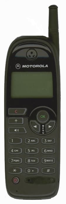
Click to zoom
Application Details
- Equipment Class
- PCE - PCS Licensed Transmitter held to ear
- Date of Grant
- Jul 30, 1998
- Application Purpose
- Original Equipment
- Date of Application
- May 27, 1998
- Frequency Range
- 1850.20000000 - 1909.80000000
- Company
- Motorola Mobility LLC
- Country
- United States
Documents & Files
Document Text
Text extracted from the exhibit documents filed with the FCC. Open a document above to read the original.
Users Manual
APPLICANT: MOTOROLA INC.FCC ID: IHDT6YH1 EXHIBIT 15 EXHIBIT 15 Instruction Manual Exhibit Summary: This mobile station transceiver is based on the design of a European GSM model. The user functionality and features are nearly identical to that GSM model. The user instruction manual that is included in this submission is a version of the manual for that GSM model. If necessary, a final version, as updated for this product and intended for the North American market, can be provided upon request. d520.bk : 500.fm5 Page 1 Friday, May 1, 1998 3:10 PM d520.bk : 500.fm5 Page 2 Friday, May 1, 1998 3:10 PM 3 English # Options Menu Quick Access Menu d520.bk : qkref.fm5 Page 3 Friday, May 1, 1998 3:10 PM 4 English Special Keys S Press and hold to turn the phone on; press to turn the phone off. O Press to accept call, accept setting, accept option. C Press to reject call, reject setting, clear digits, reject option. [] Press to move through the menu and feature choices, or to edit an SMS message. \ Press to adjust the speaker or ringer volume. Making a Call Enter the number using the digit keys and press O . Receiving a Call To receive a phone call, press O or any other key except S or C . Ending a Call To end a phone call, press O . GSM Emergency Calls To dial the GSM emergency number, press 112O . The call will be directed to a central emergency operator. Redialling the Last Number Called When in standby mode, press OO . Dialling Phone Book Numbers To dial a specific Phone Book Number, dialLocation #O One-Touch Dialling Press and hold the appropriate digit key 1 to 9 . Locking the Keypad Press * and # simultaneously. Quick Access Features Press E followed by the appropriate key (1-9) or press E , scroll to the feature and press O to select. d520.bk : qkref.fm5 Page 4 Friday, May 1, 1998 3:10 PM Introduction 1 English Introduction Congratulations on your purchase of a cellular telephone from Motorola , the world leader in cellular technology.All Motorola cellular telephones are manufactured to exacting specifications and world-class quality standards, and are designed to withstand the harshest environmental conditions. Our commitment to Total Customer Satisfaction and over sixty five years of experience in personal communications mean you can depend upon the quality of this Motorola product. This cellular telephone has been designed for use with networks conforming to the GSM900 standard (Global System for Mobile communications). By using digital communications methods, your phone provides a number of advantages over traditional cellular systems:• Superior speech quality is attained without the usual background noises and interference.• Your conversation may be encrypted for security. Conversations cannot be eavesdropped using scanning equipment when the signal is encrypted. • You are not restricted to using your phone within one country.Your subscriber number is not contained within the phone as with other systems. Instead, a 'Smart Card' known as a SIM (Subscriber Identity Module) is supplied by your Cellular Service Provider. All call billing is made to the subscriber number on the card whether it is used in this or any other GSM 900 unit. d520.bk : intro.fm5 Page 1 Friday, May 1, 1998 3:10 PM Introduction 2 English Understanding this Manual Many of your phone options are accessed by a simple menu system. A full description of the menus and how to move around them is covered in the later section Menu Navigation . When the manual describes the use of each menu item, it will be assumed that you are familiar with the menu system. Key Presses Key presses are represented in this manual using symbols so that you may locate and use the required sequence quickly. A sequence of key presses may be shown as follows: 1 0 C This means that you should press the 1 key followed by the 0 key and then the C key, in sequence, not simultaneously.A The key shapes represented in this manual may differ from the keys on your phone. Entering Information When you are requested to enter information, such as the number of the phone you wish to call, this is represented in bold type. For example:Phone No. - enter the required telephone number. PIN Code - enter your Personal Identification Number. Unlock Code - enter your unlock code. Location - enter the Phone Book location number. Prompts and Messages Your phone responds to key presses by displaying either easy to understand prompts that guide you to the next action, or simple messages confirming that your action is complete. Prompts and messages are represented in this manual in LCD style, for example:Enter PIN or Completed . Other Symbols You will find the following symbols used throughout this manual:A A Note contains additional information which is relevant to the feature/item. ! A Caution contains important additional information which is relevant to the efficient and/or safe usage of your phone. d520.bk : intro.fm5 Page 2 Friday, May 1, 1998 3:10 PM Introduction 3 English Total Customer Satisfaction At Motorola, Total Customer Satisfaction is a top priority. If you have a question, a suggestion or a concern about your Motorola Cellular Phone, Motorola wants to hear from you.Please contact the Motorola Cellular Response Centre by fax on: +44 (0) 131 458 6732, or use one of the local phone numbers in the following countries:Austria 0660 7246 Belgium 0800 72 370 Denmark 43 43 15 56 Egypt 02 3411800 Eire 01 402 6887 Finland 0800 117 036 France 0801 63 67 03 Germany 0180 35050 Greece 00800 441 28150 Italy 02 696 333 16 Jordan 06 863750 Kuwait 484 2000 Ext 1177 Lebanon 01 744156 Luxembourg 0800 21 99 Netherlands 0800 022 27 43 Norway 22 55 10 04 Oman 790925 Portugal 01 318 0051 Qatar 418999 Saudi Arabia 01 2303294 South Africa 0800 11 48 49 Spain 902 100 077 Sweden 08 445 1210 Switzerland 0800 553 109 Turkey 0212 2729090 UK 0500 55 55 55 United Arab Emirates 04 32 11 66 For e-mail queries contact: [email protected] For Internet queries contact: http://www.mot.com Motorol…
Text truncated - open the document above for the full version.
Attestation Statements
APPLICANT: MOTOROLA INC.FCC ID: IHDT6YH1 ATTESTATION OF COMPLIANCE TESTING The transceiver type IHDT6YH1 has been tested in accordance with the requirement contained in the appropriate Commission’s regulations. To the best of my knowledge, these tests were performed using measurement procedures consistent with industry or Commission standards and demonstrate that this equipment complies with the appropriate standards. Each unit manufactured, imported or marketed, will conform to the sample tested within the variations that can be expected due to quantity production and testing on a statistical basis. I further certify that the necessary measurements were made at Motorola, located at 600 North U. S. Highway 45, Libertyville, Illinois with the exception of Radiated Spurious Emissions testing which took place at Elite Electronic Engineering Company, located at 1516 Centre Circle, Downers Grove, Illinois. NAME:Rashid Osmani TITLE:Engineering Manager PCS Development Cellular Subscriber Group SIGNED: __________________________ DATE: _____________
Attestation Statements
APPLICANT: MOTOROLA INC.FCC ID: IHDT6YH1 STATEMENT OF CERTIFICATION The technical data supplied with this application, having been taken under my supervision is hereby duly certified. I also certify that this transmit equipment (FCC ID: IHDT6YH1) for mobile station cellular system use is in full compliance with all applicable parts of the FCC Rules. The following is a statement of my qualifications: NAME:Andrew Senycia TITLE:Lead Engineer PCS RF Development Cellular Subscriber Group SIGNED: __________________________ DATE: _____________
Cover Letter(s)
May 28, 1998 REQUEST FOR CONFIDENTIALITY CONTAINED WITHIN Federal Communications Commission Authorization and Evaluation Division 7435 Oakland Mills Road Columbia, Maryland 21046 Re:Application for Broadband PCS Transceiver Type Acceptance Gentlemen: Motorola, Inc., Cellular Subscriber Sector, 600 N. U.S. Highway 45, Libertyville, Illinois 60048-5343 herein submits "Electronic" Application for Equipment Authorization (to be followed by mailing of Check Number 120-641890 in the amount of $580.00 along with Form 159) for Type Acceptance of a Broadband Personal Communications Services Transceiver under FCC Rule Part 24(E), FCC ID: IHDT6YH1. Motorola is also the manufacturer of this equipment. Pursuant to §0.459 of the Commission's rules (CFR 47), Motorola requests confidentiality for portions of the material contained in this application and that the identified material be withheld from public inspection following the grant of this authorization. This material, as indicated by request for confidentiality of the items during the electronic submission process, includes: Exhibit 2, Description of Modulation System; Exhibit 3, Means for Stabilizing Frequency; Exhibit 4, Circuit Diagrams and Exhibit 5, Function of Active Semiconductor Devices. Specifically, these exhibits contain information relating to circuit function and complexity which could be of benefit to competitors. This material contains Motorola's trade secrets and confidential information which Motorola does not customarily release to the public and which is otherwise not generally available to the public. Please contact me by telephone at (847) 523-7373, by facsimile at (847) 523-2350 or by correspondence at the address herein if there are any further questions or additional information needed concerning this filing. Regards, (signed, John A. Kalenowsky) John A. Kalenowsky Patent Engineer/FCC Liaison Cellular Subscriber Sector 600 N. U.S. Highway 45 Libertyville, IL 60048-5343 Enclosures
Cover Letter(s)
MOTOROLA, INC. July 24, 1998 Mr. Greg Czumak Federal Communications Commission Equipment Authorization Division 7435 Oakland Mills Road Columbia, Maryland 21046 Re:Request for Additional Technical Information, received by E-Mail on July 24, 1998, regarding pending Application for Type Acceptance, FCC ID: IHDT6YH1, [Correspondance ID: 2232]. Dear Mr. Czumak: In response to item 1 of the referenced request, to "Please submit the SAR report, electronically via the internet.", this has been uploaded as six files with the "Exhibit Type" of "RF Exposure Info." As we have reached agreement with Kwok Chan for past submittals, the files consist of the following: our report, a procedure document, and 4 data set files. The data set files are two for each antenna position (extended and retracted) showing the area and zoom scans for the test channel and ear position for which the highest SAR value was found for that antenna position. The report shows a tabular summary of measured SAR values for all twelve test conditions (low, middle, and high channel; left and right side; extended and retracted antenna position). In response to item 2 of the above request, to "Please indicate the EIRP of the EUT, based on the measured conducted output power of 1W and the antenna gain.", the 1W conducted output power indicated is during the transmit burst (this technology operates with a 1/8 duty cycle) and the maximum gain in any direction was found to be 4.0 dBi at mid channel with the antenna in the extended position. Therefore, maximum EIRP for this product would be 2.5W. Also, an error was discovered in the description of the battery system for this product in Exhibit 11. A corrected version of Exhibit 11 has been uploaded. I trust that this will satisfy the request and allow the Grant to be issued for this equipment. Please contact me by telephone at (847) 523-7373 or by facsimile at (847) 523-2350 if there are any further questions or additional information needed concerning this filing and/or this reply. Regards, John A. Kalenowsky Patent Engineer/FCC Liaison Cellular Subscriber Sector cc:File
External Photos
APPLICANT: MOTOROLA INC. FCC ID: IHDT6YH1 EXHIBIT 14a Page 1 of 3 EXHIBIT 14a Equipment Photographs External This Exhibit contains photographs of the . transceiver board Front View...........................................2 Back View............................................3 APPLICANT: MOTOROLA INC. FCC ID: IHDT6YH1 EXHIBIT 14a Page 2 of 3 APPLICANT: MOTOROLA INC. FCC ID: IHDT6YH1 EXHIBIT 14a Page 3 of 3
ID Label/Location Info
APPLICANT: MOTOROLA INC.FCC ID: IHDT6WU1 EXHIBIT 13 PAGE 1 OF 2 EXHIBIT 13 FCC Labeling Information Exhibit Summary: EXHIBIT 13 contains a diagram of the label that will be placed on the back of each mobile station transceiver. Contents: Mobile Station FCC Label ...........................................................2 APPLICANT: MOTOROLA INC.FCC ID: IHDT6WU1 EXHIBIT 13 PAGE 2 OF 2 Mobile Station FCC Label: A label similar to the one shown below will be permanently affixed to the outside back of each mobile station transceiver produced (see EXHIBIT 14 for label placement on the transceiver). The label as shown is aproximately 2:1 scale. FCC ID: IHDT6YH1
Internal Photos
General Product Description The Shure Model UlH is a UHF, up (microprocessor) controlled, transmitter operating over the frequency range of 782 to 830 MHz (with two different models). The transmitter features a minimum of six hour battery life using 2 'AA' alkaline batteries, an LCD readout of group/channel with battery status indicator, a metal enclosure, and utilizes an external antenna to provide optimum range. This product is intended for use in high-end installed sound, rental, and concert sound markets. Special Features 1. Frequency agile, microprocessor controlled. Model number determines frequency band of operation as well as size of minimum step of synthesizer (center frequency). For example: UL-UA operates between 782-806 MHz on 125 kHz centers for a total of 191 frequencies. 2. A minimum of 20 compatible systems (UA). 3. Tone-key squelch. 4. (2) 1.5 Volt "AA" battery operation with electrical reverse battery protection. 5. Switchcraft "Tiny Q-G?" type input connector (4 pin, mates with switchcraft TA4F or equivalent). Supports WL83A, WL84A, WL93, WM98, WCM16, WH10TQG, and WA302 mics, headsets, and cables. 6. Six hour minimum battery life for 2 'AA, new alkaline batteries. 7. Rugged, all-metal construction. 8. Power On/Off two position miniature toggle switch located on top of unit with green LED power on indicator:. 9. Mode and Set momentary pushbuttons which also function as Power/frequency lockout buttons located under battery door. 10. LCD display includes group, channel and low. battery condition. 11. Screwdriver adjustable audio gain via rotary potentiometer.
Operational Description
APPLICANT: MOTOROLA INC.FCC ID: IHDT6YH1 EXHIBIT 1 PAGE 1 OF 7 Type Acceptance Requirements The information in this exhibit is in accordance with requirements for type acceptance as outlined in the FCC Rules and Regulations, CFR Part 2 Sections 2.983 - 2.999 and 47 CFR Part 24 Sections 24.52, 24.235 and 24.238. Section 2.983: Application for Type Acceptance (a) Name of Applicant: Motorola Inc., Motorola is also the manufacturer of the equipment described herein. (b)Identification of Equipment: IHDT6YH1 (c)Quantity Production: Quantity production is planned. (d)Technical Description: The transmit and receive equipment (FCC ID: IHDT6YH1) for which type acceptance is desired, is intended for use as a mobile station cellular transceiver in the broadband US PCS frequency region and is designed in compliance with the FCC Rules and Regulations Parts 2 and 24. (1) Types of Emissions: Designator 250KGXW The mobile station transceiver transmits a Gaussian Minimal Shift Keying (GMSK) modulated carrier having a BT product of 0.3. The bandwidth of a GMSK modulated carrier having a BT of 0.3 is 250 kHz (see EXHIBIT 2). This results in 250K for the first four characters of the emissions designator. GMSK is the same as Minimal Shift Keying (MSK) except that the NRZ data has been filtered prior to modulation. As a result, GMSK, like MSK can generally be thought of as frequency shift keying (FSK), or Offset Quadrature Phase Shift Keying (OQPSK), and can be modulated and demodulated using either of these techniques. Motorola's mobile station transceiver is based off of the OQPSK technique, which is a type of phase modulation. This corresponds to G, for Types of Modulation. APPLICANT: MOTOROLA INC.FCC ID: IHDT6YH1 EXHIBIT 1 PAGE 2 OF 7 The mobile station transceiver uses a digital signal representing sampled, quantized voice or other audio information or command data to modulate the main carrier in a Time Division Multiple Access (TDMA) fashion. This corresponds to X for nature of modulating signals. The symbol 1 excludes time- division multiplex, and the other choices for digital modulating signals either state “Two or more channels containing quantized or digital information” or “Composite system with one or more channels containing quantized or digital information, together with one or more channels containing analogue information. The information transmitted is a combination of command data and telephony (sampled quantized voice or other audio signals). This corresponds to W for Types of Information Transmitted, defined as “Combination of above” which would be the combination of symbol D, “Data transmission, telemetry, telecommand”, and symbol E, “Telephony (including sound braodcasting)”. (2) Frequency Range This equipment is designed to transmit from 1850- 1910 MHz. This frequency range corresponds to Blocks A, D, B, E, F and C of the US PCS frequency band. (3) Range of Operating Powers The transmitter output power range is +0 dBm to +30 dBm. This range of output power is controlled to sixteen discrete levels in increments of 2 dBm. This is a dynamic adjustment carried out under the command and supervision of the cellular base station and is used to control the uplink power from the mobile within a cell as the position of the mobile changes. Transmit power tuning adjustments are made at all sixteen levels: Refer to EXHIBIT 7. APPLICANT: MOTOROLA INC.FCC ID: IHDT6YH1 EXHIBIT 1 PAGE 3 OF 7 (4) Maximum Power Rating (Sec. 24.232) In no case may the peak output power of a mobile station transmitter exceed 32 dBm. (5) Applied Voltage and Currents into the Final Amplifying Device: Refer to EXHIBIT 6. (6) Function of Active Devices: Refer to EXHIBIT 5. (7) Complete Circuit Diagrams: Refer to EXHIBIT 4. (8) Instruction Manual: Refer to EXHIBIT 15. Because the mobile station transceiver is based on the design of a European GSM model, and, more specifically, the user functionality and features are nearly identical to this GSM model. The user instruction manual that is included in this submission is a copy of the GSM manual and should be viewed as a preliminary version user manual in state very near that of the final version intended to ship with the equipment. If necessary, when available, the final version can be provided upon request. (9) Tune-Up Procedure Several adjustments are performed on the transmitter at a radio level before the mobile station transceiver is fully operational. Refer to EXHIBIT 12. (10) Means for Stabilizing Frequency: Refer to EXHIBIT 3. (11) Means for Suppressing Spurious Radiation Spurious and harmonic suppression is achieved through multiple means. 1. Radio Architecture: APPLICANT: MOTOROLA INC.FCC ID: IHDT6YH1 EXHIBIT 1 PAGE 4 OF 7 a. Proper selection of local oscillator frequencies and intermediate frequencies (IF) to minimize spurious products. b. Minimization of broadband noise both in- band and out-of-band through the combination of gain/noise figure architecture in the transmitter exciter stages and proper control of the transmitter's gain. 2. Physical Construction and Circuit Design Techniques: a. Sources of spurious radiation such as frequency source circuitry and high gain circuitry within the equipment are assembled under grounded conductive cans on the circuit boards forming a localized shielded enclosure within the unit. b. Physical separation of frequency sources from high gain circuitry. c . Multilayer PC boards allow use of stripline for routing signals. (12) Means for Limiting Modulation The carrier is modulated with Gaussian Minimal Shift Keying (GMSK) having a BT product of 0.3. By definition, the peak frequency deviation of GMSK is one-fourth of the bit rate, or 270.833/4 = 67.7083 kHz. There is a theoretical phase trajectory that any given bit stream should ideally follow over the period of one time slot. However, imperfections in the modulation process can introduce errors which produce variations from the ideal trajectory. By design, the transmitter will follow …
Text truncated - open the document above for the full version.
Parts List/Tune Up Info
APPLICANT: MOTOROLA INC.FCC ID: IHDT6YH1 EXHIBIT 12 PAGE 1 OF 3 EXHIBIT 12 Transceiver Adjustments Exhibit Summary: EXHIBIT 12 contains information pertaining to radio level adjustments that are performed during the manufacturing process. Contents: Frequency Adjustment...............................................................2 Transmit Output Power Adjustment.......................................2 Receive I and Q Balance .............................................................3 Receive Audio Level Adjustment.............................................3 APPLICANT: MOTOROLA INC.FCC ID: IHDT6YH1 EXHIBIT 12 PAGE 2 OF 3 Frequency Adjustment: In order to guarantee that the AFC algorithm will be able to adjust the transmitter to within the specified 0.1 ppm described in EXHIBIT 3 it is necessary to measure, adjust, and store a compensating value of an un-AFCed carrier. This takes place during the manufacturing process. The mobile station transceiver is set to transmit on channel number 661 and is keyed. The frequency transmitted is measured and the offset from the desired 1880 Mhz is calculated. The voltage necessary to be applied to the reference oscillator circuit, to cause the transmitted frequency to be within 100 Khz of desired, is calculated, converted to a digital format and stored in non-volatile memory. The resolution of the tuning ability is also verified to be less than 78 Hz increments. This ensures the ability to tune to within the necessary 0.1 ppm. Transmit Output Power Adjustment: In order to guarantee that the power control circuitry will be able to adjust the transmitter to within the specified limits shown in the table of EXHIBIT 6 it is necessary to measure, adjust, and calculate calibration values to compensate for manufacturing and component tolerances in the transmitter lineup. This takes place during the manufacturing process. The mobile station transceiver is set to transmit a pseudo random data sequence on channel number 661 and is keyed. The output power is measured at both highest and lowest power steps. The voltage necessary to be applied to the power control circuitry, to cause the transmitted power to be within the limits of the table in EXHIBIT 6, is calculated. Also, the voltages required to meet specified levels of the intermediate power steps are calculated. This array of values are converted to a digital format and stored in non-volatile memory. Finally, the mobile station transceiver is set to transmit a pseudo random data sequence on channel numbers 512 and 810 and is keyed to power step 6. A further algorithm is run to calculate offset values for the values stored in non-volatile memory above to account for tolerances due to frequency variation. This ensures the ability to control the output power across the USPCS band. APPLICANT: MOTOROLA INC.FCC ID: IHDT6YH1 EXHIBIT 12 PAGE 3 OF 3 Receive I and Q Balance: With the aide of a Hewlett Packard 8922 GSM Test Set the relative levels of the demodulated quadrature baseband analog signals I and Q are adjusted to achieve a balance between the two amplitudes. With the mobile station in a call with the 8922 use the transceiver’s internal command to output the power of the I and Q signals. Store the adjusting factors into non-volatile memory to achieve a balance between the amplitudes of the two signals. Receive Audio Level Adjustment: With the aid of a Hewlett Packard 8922 GSM Test Set the receive audio level Automatic Gain Control (AGC) circuitry is adjusted to set the demodulated receive audio to calibrated levels. Once calibrated, the receive levels are then used as an indication of receive signal strength. With the mobile station in a call with the 8922 use the transceiver’s internal command to output the power of the I and Q signals. For given RF input power levels from the 8922 compensating gain control values are calculated to maintain a constant amplitude on each of these signals. This procedure is repeated over varying power input levels and over many discrete frequency bands creating a matrix of compensating factors. This matrix is stored into non-volatile memory.
RF Exposure Info
APPLICANT: MOTOROLA INC.FCC ID: IHDT6YH1 EXHIBIT 1 PAGE 1 OF 7 Type Acceptance Requirements The information in this exhibit is in accordance with requirements for type acceptance as outlined in the FCC Rules and Regulations, CFR Part 2 Sections 2.983 - 2.999 and 47 CFR Part 24 Sections 24.52, 24.235 and 24.238. Section 2.983: Application for Type Acceptance (a) Name of Applicant: Motorola Inc., Motorola is also the manufacturer of the equipment described herein. (b)Identification of Equipment: IHDT6YH1 (c)Quantity Production: Quantity production is planned. (d)Technical Description: The transmit and receive equipment (FCC ID: IHDT6YH1) for which type acceptance is desired, is intended for use as a mobile station cellular transceiver in the broadband US PCS frequency region and is designed in compliance with the FCC Rules and Regulations Parts 2 and 24. (1) Types of Emissions: Designator 250KGXW The mobile station transceiver transmits a Gaussian Minimal Shift Keying (GMSK) modulated carrier having a BT product of 0.3. The bandwidth of a GMSK modulated carrier having a BT of 0.3 is 250 kHz (see EXHIBIT 2). This results in 250K for the first four characters of the emissions designator. GMSK is the same as Minimal Shift Keying (MSK) except that the NRZ data has been filtered prior to modulation. As a result, GMSK, like MSK can generally be thought of as frequency shift keying (FSK), or Offset Quadrature Phase Shift Keying (OQPSK), and can be modulated and demodulated using either of these techniques. Motorola's mobile station transceiver is based off of the OQPSK technique, which is a type of phase modulation. This corresponds to G, for Types of Modulation. APPLICANT: MOTOROLA INC.FCC ID: IHDT6YH1 EXHIBIT 1 PAGE 2 OF 7 The mobile station transceiver uses a digital signal representing sampled, quantized voice or other audio information or command data to modulate the main carrier in a Time Division Multiple Access (TDMA) fashion. This corresponds to X for nature of modulating signals. The symbol 1 excludes time- division multiplex, and the other choices for digital modulating signals either state “Two or more channels containing quantized or digital information” or “Composite system with one or more channels containing quantized or digital information, together with one or more channels containing analogue information. The information transmitted is a combination of command data and telephony (sampled quantized voice or other audio signals). This corresponds to W for Types of Information Transmitted, defined as “Combination of above” which would be the combination of symbol D, “Data transmission, telemetry, telecommand”, and symbol E, “Telephony (including sound braodcasting)”. (2) Frequency Range This equipment is designed to transmit from 1850- 1910 MHz. This frequency range corresponds to Blocks A, D, B, E, F and C of the US PCS frequency band. (3) Range of Operating Powers The transmitter output power range is +0 dBm to +30 dBm. This range of output power is controlled to sixteen discrete levels in increments of 2 dBm. This is a dynamic adjustment carried out under the command and supervision of the cellular base station and is used to control the uplink power from the mobile within a cell as the position of the mobile changes. Transmit power tuning adjustments are made at all sixteen levels: Refer to EXHIBIT 7. APPLICANT: MOTOROLA INC.FCC ID: IHDT6YH1 EXHIBIT 1 PAGE 3 OF 7 (4) Maximum Power Rating (Sec. 24.232) In no case may the peak output power of a mobile station transmitter exceed 32 dBm. (5) Applied Voltage and Currents into the Final Amplifying Device: Refer to EXHIBIT 6. (6) Function of Active Devices: Refer to EXHIBIT 5. (7) Complete Circuit Diagrams: Refer to EXHIBIT 4. (8) Instruction Manual: Refer to EXHIBIT 15. Because the mobile station transceiver is based on the design of a European GSM model, and, more specifically, the user functionality and features are nearly identical to this GSM model. The user instruction manual that is included in this submission is a copy of the GSM manual and should be viewed as a preliminary version user manual in state very near that of the final version intended to ship with the equipment. If necessary, when available, the final version can be provided upon request. (9) Tune-Up Procedure Several adjustments are performed on the transmitter at a radio level before the mobile station transceiver is fully operational. Refer to EXHIBIT 12. (10) Means for Stabilizing Frequency: Refer to EXHIBIT 3. (11) Means for Suppressing Spurious Radiation Spurious and harmonic suppression is achieved through multiple means. 1. Radio Architecture: APPLICANT: MOTOROLA INC.FCC ID: IHDT6YH1 EXHIBIT 1 PAGE 4 OF 7 a. Proper selection of local oscillator frequencies and intermediate frequencies (IF) to minimize spurious products. b. Minimization of broadband noise both in- band and out-of-band through the combination of gain/noise figure architecture in the transmitter exciter stages and proper control of the transmitter's gain. 2. Physical Construction and Circuit Design Techniques: a. Sources of spurious radiation such as frequency source circuitry and high gain circuitry within the equipment are assembled under grounded conductive cans on the circuit boards forming a localized shielded enclosure within the unit. b. Physical separation of frequency sources from high gain circuitry. c . Multilayer PC boards allow use of stripline for routing signals. (12) Means for Limiting Modulati…
Text truncated - open the document above for the full version.
Contact Information
Applicant
Jeff Narducci(Director Product Compliance)
Technical Specifications
| # | Rule Parts | Frequency Range | Power Output | Emission | Tolerance |
|---|---|---|---|---|---|
| 1 | 24E | 1.85 GHz - 1.91 GHz | 2 W | 250KGXW | 0.1000000000 ppm |
Other Applications from Motorola Mobility LLC
IHDT6AC8
Sep 15, 2026Qi2 wireless charger
Equipment Class
DCD - Part 15 Low Power Transmitter Below 1705 kHzIHDT6AC6
Sep 14, 2026Wireless Earphones
Equipment Class
JAB - Part 15 Class B Digital DeviceIHDT6AC7
Sep 11, 2026Smart Watch
Equipment Class
JAB - Part 15 Class B Digital DeviceIHDT56AX5
Aug 28, 2026Mobile Cellular Phone
Equipment Class
JBP - Part 15 Class B Computing Device PeripheralIHDT56AW9
May 12, 2026Smart Watch
Equipment Class
NII - Unlicensed National Information Infrastructure TX