IHDT6YW1Wideband PCS Personal Transceiver
Motorola Mobility LLC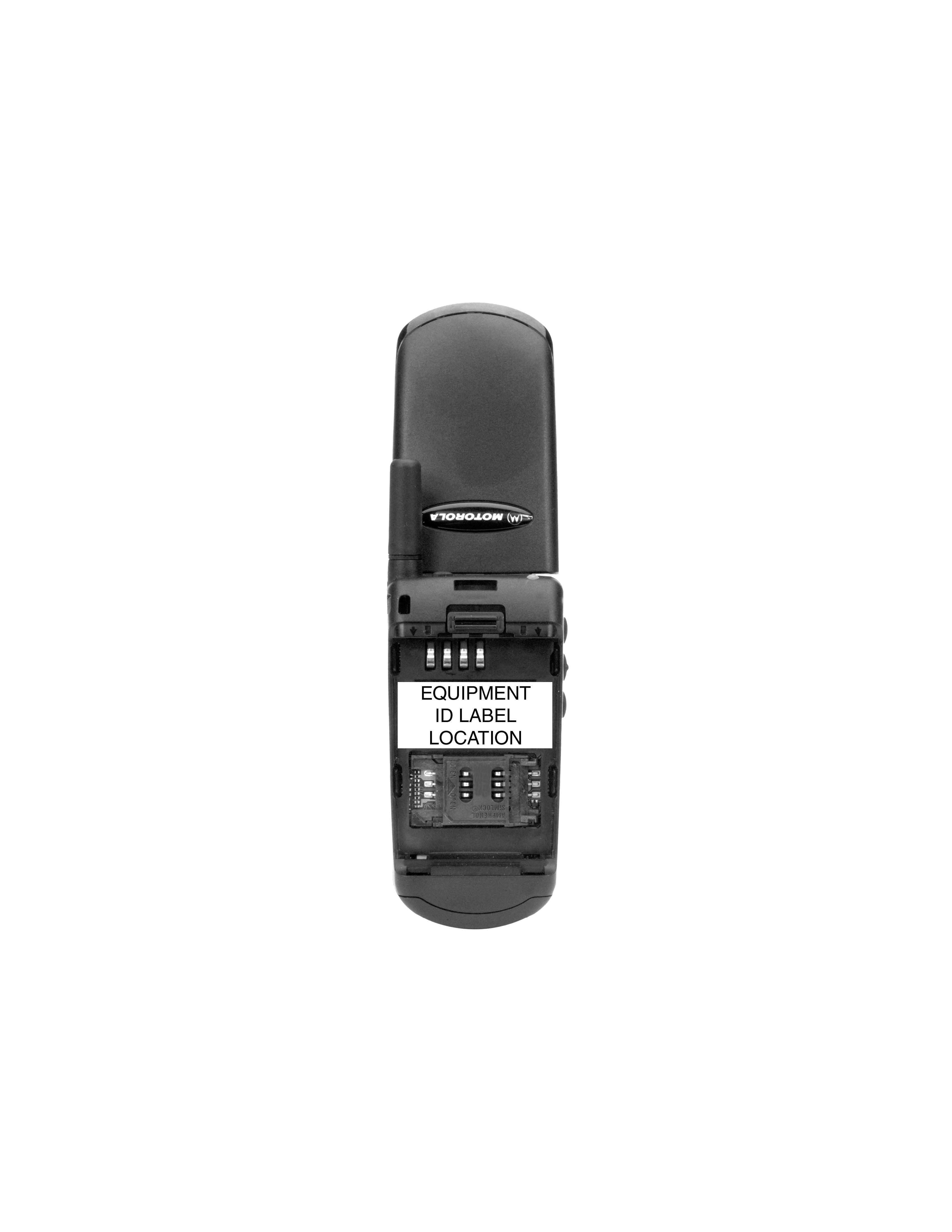
Click to zoom
Application Details
- Equipment Class
- PCE - PCS Licensed Transmitter held to ear
- Date of Grant
- Feb 25, 1999
- Application Purpose
- Original Equipment
- Date of Application
- Dec 10, 1998
- Equipment Note
- Wideband PCS Personal Transceiver
- Frequency Range
- 1850.20000000 - 1909.80000000
- Company
- Motorola Mobility LLC
- Country
- United States
Documents & Files
Document Text
Text extracted from the exhibit documents filed with the FCC. Open a document above to read the original.
Users Manual
APPLICANT: MOTOROLA INC.FCC ID: IHDT6YW1 Page 1 of 1EXHIBIT 14 EXHIBIT 14 Instruction Manual Exhibit Summary: This mobile station transceiver is based on the design of a European GSM model. The user functionality and features are nearly identical to that GSM model. The user instruction manual that is included in this submission is a version of the manual for that GSM model. If necessary, a final version, as updated for this product and intended for the North American market, can be provided upon request.
Users Manual
English Options Menu Quick Access Menu ‡ Quick Reference st210_en.bk : qkref.fm5 Page 1 Tuesday, October 27, 1998 10:42 AM English Special Keys S Press to turn phone on and off. O Press to accept call, setting, option,... C Press to reject call, setting, option,... E Press to enter the Quick Access features. $ Press to access the options or phone book menus. <> Press to select entries and menu options. , Press to add a phone book entry. f Press to call Voicemail. Making a Call Enter C O . Receiving a Call Open the phone, or press O , < or > . Ending a Call Press O , C or close the phone. Making an Emergency Call Enter 112O . The call will be directed to a central emergency operator. Quick Access Features Press E followed by the appropriate key, or press E , scroll to the feature and press O to select. Redialling the Last Number Called 1 Press O to display the last number dialled. 2 Press O to call the number. One-Touch Dialling Press and hold the appropriate digit key 1 to 9 . Storing Numbers in the Phone Book 1 Press , to access the Phone Book. 2 Press O to select phone memory, or <O to select SIM card memory. 3 Enter C O , then H O , then G O . Dialling Phone Book Numbers Enter G > O . Stopping a Call Alert Press either of the volume buttons when the phone is ringing or vibrating. This will stop the alert but not answer the call. Quick Reference st210_en.bk : qkref.fm5 Page 2 Tuesday, October 27, 1998 10:42 AM Introduction 1 English Introduction Welcome Congratulations on your purchase of a phone from Motorola , the world leader in cellular technology. The phones are packed with features that put you in control and give you unrivalled power, whilst remaining discrete. Control • Customisable Quick Access Menu E - Place nine of your most frequently used features in your own personal menu so that they can be accessed with just two key presses. Icons make each feature easy to identify. Power • Superb battery performance G - Each phone is capable of several hours conversation or several days standby, but is still small and light. • Dual Band - versions of the phone include the powerful dual band feature which means that they can use both 900 and 1800 MHz bands for greater call success and allow wider roaming opportunities. ! Before you use your phone, please see the ‘Your Battery’ section for important information on charging a new battery. Discretion • VibraCall™ L - In locations where you don’t want your phone to ring, or which are too noisy to hear your phone ring, your phone can vibrate to alert you of a call. • Wearable Holster - Wear your phone in a stylish holster on your belt. It is small enough and light enough to keep with you almost anywhere. • Stop Call Alert - Press either of the volume buttons when the phone is ringing or vibrating. This will stop the alert but not answer the call. Personality™ This cellular telephone incorporates Personality ™. Unique to Motorola , Personality ™ removes the complexity of cellular communications by guiding you through the features and presenting you with simple choices every step of the way. Personality ™ also allows you to personalise the way you use your phone - for example, different ringer tones, a phone book and network selection preferences - all presented with clarity and simplicity. In this manual, each of the Personality ™ features is identified with an j symbol to indicate that it is customisable to meet your requirements. st210_en.bk : intro.fm5 Page 1 Tuesday, October 27, 1998 10:42 AM Introduction 2 English Understanding this Manual Many of your phone options are accessed by a simple menu system. A full description of the menus and how to move around them is covered in the next section Menu Navigation . When the manual describes the use of each menu item, it will be assumed that you are familiar with the menu system. Key Presses Key presses are represented in this manual using symbols so that you may locate and use the required sequence quickly. A sequence of key presses may be shown as follows:$OCThis means that you should press the $ key followed by the O key and then the C key, in sequence, not simultaneously. Entering Information When you are requested to enter information, such as the number of the phone you wish to call, this is represented in bold type. For example:C - enter the required telephone number. A - enter your Personal Identification Number. B - enter your unlock code. G - enter the Phone Book location number. Prompts and Messages Your phone responds to key presses by displaying either easy to understand prompts that guide you to the next action, or simple messages confirming that your action is complete. Prompts and messages are represented in this manual in LCD style, for example:Enter PIN or Completed . Other Symbols You will find the following symbols used throughout this manual:A A Note contains additional information which is relevant to the feature/item. ! A Caution contains important additional information which is relevant to the efficient and/or safe usage of your phone. j This symbol indicates that the feature is a Personality ™ feature that can be customised to meet your requirements. i This symbol indicates a short key sequence for the feature. st210_en.bk : intro.fm5 Page 2 Tuesday, October 27, 1998 10:42 AM Introduction 3 English Menu Navigation A large number of your phone's options are accessed by using menus which use a common approach for selection, change and cancellation.Please read this section carefully before attempting to access a menu option. When you understand the common approach to menu navigation and how the menus are shown on the page, you will be able to access and change options with ease. Entering the Menus Two different keys (three on flip phones) are used to access the menus:$ enters the Options menu whilst in standby mode; enters the In-call menu during a call. E enters the Quick Access menu. Once entered, the menus use the $ , < , > , O and C keys in a common manner to access,…
Text truncated - open the document above for the full version.
Attestation Statements
APPLICANT: MOTOROLA INC. FCC ID: IHDT6YW1 Page 1 of 1 ATTESTATION OF COMPLIANCE TESTING The transceiver type IHDT6YW1 has been tested in accordance with the requirements contained in the appropriate Commission regulations. To the best of my knowledge, these tests were performed using measurement procedures consistent with industry or Commission standards and demonstrate that this equipment complies with the appropriate standards. Each unit manufactured imported or marketed, will conform to the sample tested within the variations that can be expected due to quantity production and testing on a statistical basis. I further certify that the necessary measurements were made at Motorola, located at 600 North U.S. Highway 45, Libertyville, Illinois with the exception of Radiated Spurious Emissions testing which took place at Elite Electronic Engineering Company, located at 1516 Centre Circle, Downers Grove, Illinois. NAME: Roger Jellicoe TITLE: Senior Resource Manager PCS Development EMEACSG SIGNED:__(signed)______________ DATE:___12/08/1998____
Attestation Statements
APPLICANT: MOTOROLA INC.FCC ID: IHDT6YW1 Page 1 of 1 STATEMENT OF CERTIFICATION The technical data supplied with this application, having been taken under my supervision is hereby duly certified. I also certify that this transmit equipment (FCC ID: IHDT6YW1) for mobile station Wideband PCS System use is in full compliance with all applicable parts of the FCC Rules. The following is a statement of my qualifications: BSc. Physics, Hebrew University, Jerusalem-Israel- October 1988 BSc. Electrical Engineering, Technion, Haifa-Israel- August 1990 8 Years experience in radio and electronic circuit design. NAME:Eli Sasson TITLE:Lead Engineer PCS Development EMEACSG SIGNED:__(signed)______________ DATE:___12/08/1998____ I hereby certify that the above application was prepared under my direction and that to the best of my knowledge and belief, the facts set forth in this application and accompanying technical data are true and correct. NAME:Jim Angel TITLE:Section Manager PCS Development EMEACSG SIGNED:__(signed)______________ DATE:___12/08/1998____
Cover Letter(s)
December 11, 1998 REQUEST FOR CONFIDENTIALITY CONTAINED WITHIN Federal Communications Commission Authorization and Evaluation Division 7435 Oakland Mills Road Columbia, Maryland 21046 Re: Application for Broadband PCS Transceiver Equipment Authorization (Certification) Gentlemen: Motorola, Inc., Cellular Subscriber Sector, 600 N. U.S. Highway 45, Libertyville, Illinois 60048-5343 herein submits "Electronic" Application for Equipment Authorization (to be followed by submission of Check Number 120-672441 in the amount of $610.00 along with Form 159) for Certification of a Broadband Personal Communications Services Transceiver under FCC Rule Part 24(E), FCC ID: IHDT6YW1. Motorola is also the manufacturer of this equipment. In addition to confidentiality for the entire application prior to grant (per 47CFR0.457(d)(1) (ii) ), Motorola requests, pursuant to 47CFR0.459, post-grant confidentiality for portions of the material contained in this application such that the identified material will be withheld from public inspection following the grant of this authorization. This material, as indicated by request for confidentiality of the items during the electronic submission process and further identified by their listing in RED on the List of Exhibits attached hereto, includes: Motorola Exhibit 2, Description of Modulation System (submitted to EAS as "Operational Description"); Motorola Exhibit 3, Means for Stabilizing Frequency (submitted to EAS as "Operational Description"); and Motorola Exhibit 4, Circuit Diagram (submitted to EAS as "Schematics"). Specifically, these exhibits contain information relating to circuit function and complexity which could be of benefit to competitors. This material contains Motorola's confidential information and trade secrets which Motorola does not customarily release to the public and which is otherwise not generally available to the public. Please contact me by telephone at (847) 523-7373, by facsimile at (847) 523-2350 or by correspondence at the address herein if there are any further questions or additional information needed concerning this filing. Regards, (signed, John A. Kalenowsky) John A. Kalenowsky Patent Engineer/FCC Liaison Cellular Subscriber Sector 600 N. U.S. Highway 45 Libertyville, IL 60048-5343 Enclosures APPLICANT: MOTOROLA INC.FCC ID: IHDT6YW1 Page 1 of 1INDEX List of Exhibits EXHIBIT 1:General Certification Information EXHIBIT 2:Description of Modulation System* EXHIBIT 3:Means for Stabilizing Frequency* EXHIBIT 4:Circuit Diagrams* EXHIBIT 5:Voltages and Currents into Final Amplifying Devices EXHIBIT 6:RF Output Power Measurements EXHIBIT 7:Radiated Spurious Emissions Measurements EXHIBIT 8:Occupied Bandwidth Measurements EXHIBIT 9:Conducted Spurious Emissions Measurements EXHIBIT 10:Frequency Stability Measurements EXHIBIT 11:FCC Labeling Information EXHIBIT 12:Equipment Photographs (External) EXHIBIT 13:Equipment Photographs (Internal) EXHIBIT 14:Instruction Manual Supplemental Exhibits (Un-numbered) Attestation of Compliance Testing Certification of Data RF Exposure Evaluation Statement * These Exhibits submitted with Request for Post Grant Confidentiality.
External Photos
APPLICANT: MOTOROLA INC. FCC ID: IHDT6YW1 Page 1 of 3 EXHIBIT 12 EXHIBIT 12 Equipment Photographs (External) Exhibit Summary: EXHIBIT 12 contains external photographs of the transceiver. Contents: Front View............................................................................2 Back View.............................................................................3 APPLICANT: MOTOROLA INC.FCC ID: IHDT6YW1 Page 2 of 3EXHIBIT 12 APPLICANT: MOTOROLA INC.FCC ID: IHDT6YW1 Page 3 of 3EXHIBIT 12
ID Label/Location Info
APPLICANT: MOTOROLA INC.FCC ID: IHDT6YW1 Page 1 of 2EXHIBIT 11 EXHIBIT 11 FCC Labeling Information Exhibit Summary: EXHIBIT 11 contains a diagram of the label that will be placed on the back of each mobile station transceiver. Contents: Mobile Station FCC Label...........................................................2 APPLICANT: MOTOROLA INC.FCC ID: IHDT6YW1 Page 2 of 2EXHIBIT 11 Mobile Station FCC Label: A label similar to the one shown below will be permanently affixed to the back of each mobile station transceiver produced (see EXHIBIT 12, page 3 for placement on the transceiver). The label as shown is aproximately 2:1 scale. FCC ID: IHDT6YW1
Internal Photos
APPLICANT: MOTOROLA INC. FCC ID: IHDT6YW1 Page 1 of 3 EXHIBIT 13 EXHIBIT 13 Equipment Photographs (Internal) Exhibit Summary: EXHIBIT 13 contains internal photographs of the main transceiver board. Contents: Front Side.............................................................................2 Back Side.............................................................................3 APPLICANT: MOTOROLA INC.FCC ID: IHDT6YW1 Page 2 of 3EXHIBIT 13 APPLICANT: MOTOROLA INC.FCC ID: IHDT6YW1 Page 3 of 3EXHIBIT 12
Operational Description
APPLICANT: MOTOROLA INC.FCC ID: IHDT6YW1 Page 1 of 6EXHIBIT 1 Certification Requirements The information in this exhibit is in accordance with requirements for certification as outlined in the FCC Rules and Regulations, 47 CFR Part 2; Sections 2.1033(c), 2.1046 - 2.1057, and Part 24, Sections 24.52, 24.235 and 24.238. Section 2.1033(c):Application for Certification (1) Name of Applicant: Motorola Inc., Motorola is also the manufacturer of the equipment described herein. Mailing address indicated on Form 731. (2)Identification of Equipment: IHDT6YW1 (3)Instruction Manual: Refer to EXHIBIT 14. Because the mobile station transceiver is based on the design of a European GSM model and, more specifically, the user functionality and features are nearly identical to this GSM model, the user instruction manual that is included in this submission is a copy of the GSM manual and should be viewed as a preliminary version user manual in a state very near that of the final version intended to ship with the equipment. If necessary, when available, the final version can be provided upon request. (4) Types of Emissions: Designator 250KGXW (and determination of Emission Designator, per 2.201) The mobile station transceiver transmits a Gaussian Minimal Shift Keying (GMSK) modulated carrier having a BT product of 0.3. The bandwidth of a GMSK modulated carrier having a BT of 0.3 is 250 kHz (see EXHIBIT 2). This results in 250K for the first four characters of the emissions designator. GMSK is the same as Minimal Shift Keying (MSK) except that the NRZ data has been filtered prior to modulation. As a result, GMSK, like MSK can generally be thought of as frequency shift keying (FSK), or Offset Quadrature Phase Shift Keying (OQPSK), and can be modulated and demodulated using either of these techniques. Motorola's mobile station transceiver is based off of the OQPSK technique, which is a type of phase modulation. This corresponds to G, for Types of Modulation. APPLICANT: MOTOROLA INC. FCC ID: IHDT6YW1 Page 2 of 6 EXHIBIT 1 The mobile station transceiver uses a digital signal representing sampled, quantized voice or other audio information or command data to modulate the main carrier in a Time Division Multiple Access (TDMA) fashion. This corresponds to X for nature of modulating signals. The symbol 1 excludes time-division multiplex, and the other choices for digital modulating signals either state “Two or more channels containing quantized or digital information” or “Composite system with one or more channels containing quantized or digital information, together with one or more channels containing analogue information. The information transmitted is a combination of command data and telephony (sampled quantized voice or other audio signals). This corresponds to W for Types of Information Transmitted, defined as “Combination of above” which would be the combination of symbol D, “Data transmission, telemetry, telecommand”, and symbol E, “Telephony (including sound broadcasting)”. (5) Frequency Range This equipment is designed to transmit from 1850 - 1910 MHz. This frequency range corresponds to Blocks A, D, B, E, F and C of the US Wideband PCS frequency band. (6) Range of Operating Powers The transmitter output power range is 0 dBm to +30 dBm. This range of output power is controlled to sixteen discrete levels in increments of 2 dBm. This is a dynamic adjustment carried out under the command and supervision of the cellular base station and is used to control the uplink power from the mobile during operation as the position of the mobile changes within a cell. Transmit power tuning adjustments are made at all sixteen levels and are based on conducted power measurements: Refer to EXHIBIT 6. (7) Maximum Power Rating (Sec. 24.232) In no case may the peak “in the burst” output power of a mobile station transmitter exceed 33 dBm (2 Watts) EIRP. The Equivalent Isotropic Radiated Power (EIRP) for the unit tested was 32.8 dBm (1.9 Watts). (Refer also to EXHIBIT 6.) APPLICANT: MOTOROLA INC. FCC ID: IHDT6YW1 Page 3 of 6 EXHIBIT 1 (8) The dc voltages applied to and dc currents into the Final Amplifying Device: Refer to EXHIBIT 5. (9) Tune-Up Procedure There are no user accessible adjustments or tuning in this portable Wideband PCS transceiver. All necessary adjustments and tuning are performed during manufacture of the product. Any adjustments or tuning after service or repair are done as part of that process as special equipment is required to perform such adjustments. (10) A Schematic Diagram: Refer to EXHIBIT 4 and a description of all circuitry and devices provided for: (i) Determining and Stabilizing Frequency: Refer to EXHIBIT 3. (ii) Suppressing Spurious Radiation Spurious and harmonic suppression is achieved through multiple means. 1. Radio Architecture: a.Selection of local oscillator frequencies and intermediate frequencies (IF) to minimize spurious products. b.Minimization of broadband noise both in- band and out-of-band through the combination of gain/noise figure architecture in the transmitter exciter stages and proper control of the transmitter's gain. 2. Physical Construction and Circuit Design Techniques: a. Sources of spurious radiation such as frequency source circuitry and high gain circuitry within the equipment are assembled under grounded conductive shields forming a localized shielded enclosure within the unit. APPLICANT: MOTOROLA INC.FCC ID: IHDT6YW1 Page 4 of 6EXHIBIT 1 b.Physical separation of frequency sources from high gain circuitry. c.Multilayer PC boards allow use of stripline for routing signals. (iii) Limiting Modulation The carrier is modulated with Gaussian Minimal Shift Keying (GMSK) having a BT product of 0.3. By definition, the peak frequency deviation of GMSK is one-fourth of the bit rate, or 270.833/4 = 67.7083 kHz. There is a theoretical phase trajectory that any given bit stream should ideally follow over the period of one time slot. However, imperfections in the modulation process …
Text truncated - open the document above for the full version.
RF Exposure Info
APPLICANT: MOTOROLA INC.FCC ID: IHDT6YW1 Page 1 of 1 Radiofrequency Energy Exposure Evaluation Statement. Motorola, Inc., Personal Communications Sector, hereby certifies that, when used as stated in the operating instructions supplied, this Wideband PCS Portable Transceiver, FCC ID: IHDT6YW1, complies with the FCC’s Radiofrequency energy exposure limits for General Population/Uncontrolled environment, per FCC Rule 47CFR2.1093.
RF Exposure Info
P P a a g g e e 1 1 December 10, 1998 SAR Test Report for Motorola portable cellular phone (FCC ID IHDT6YW1). Prepared by: Paul Moller, Principal Staff Engineer Motorola Personal Communications Sector Product Safety Laboratory Libertyville, Illinois Contents 1) Introduction 2) Applicable Regulations 3) Description of Test Sample 4) Description of Motorola SAR Test Facility 5) Test Sample Conditions 6) Method of Measurement 7) SAR Test Results 8) Summary Appendix A: Included data Appendix B: SAR Measurement Operational Guide P P a a g g e e 2 2 1. Introduction The Motorola Personal Communications Sector Product Safety Laboratory has performed measurements of the maximum potential exposure to the user of portable cellular phone FCC ID IHDT6YW1. The Specific Absorption Rate (SAR) of this product was measured. This report details the test setup and equipment as well as the results of those tests. 2. Applicable Regulations Federal Communications Commission rule §2.1093(d)(2), the ANSI/IEEE C95.1 1992 and the NCRP Report Number 86 specify the maximum exposure limit of 1.6 W/kg as averaged over any 1 gram of tissue for portable devices being used within 20cm of the user in the uncontrolled environment. 3. Description of Test Sample A prototype unit serial number 7054800001 was measured. This unit is identical in physical construction, maximum radiated power levels and antenna structure to units that will be in production. It transmits in the frequency range of 1850 to 1910 MHz using GSM digital mode only. The reported maximum peak transmit EIRP for this test unit is 1.9 Watts as defined in FCC Rule §24.232. The unit was tested at its maximum transmitter power, which is nominally a peak conducted power of 1.0 Watt (average conducted power of 0.125 Watt using the 1/8 duty cycle of the GSM system). The unit is equipped with a fixed antenna that serves as both a receive and transmit antenna. The antenna has a single operating position as shown in figure 1. Figure 1. P P a a g g e e 3 3 Figure 2 shows the test unit as it is placed onto the phantom. For the purposes of the actual SAR tests the phantom head is tilted on its side by 90 degrees so that a vertically oriented measurement probe can easily scan an area where the phone is in close contact with the phantom and the SAR will be the highest. Figure 2. P P a a g g e e 4 4 4. SAR Test Facility The Motorola test facility utilized for the SAR testing of this product is the Personal Communications Sector Product Safety Laboratory, in Libertyville Illinois. The laboratory utilizes an SAR measurement system developed by Motorola and manufactured by IDX Robotics™ of Corvallis, Oregon. This system utilizes a computer controlled six axis robot to move a measurement probe to measure the SAR. The probe is calibrated at the Florida Corporate Electromagnetics Laboratory in Plantation Florida, using a procedure developed by Dr. Q. Balzano. The measurement methodology is described in IEEE Transactions on Vehicular Technology, vol. 44, no. 3, August 1995, titled Electromagnetic Energy Exposure of Simulated users of Portable Cellular Telephones. Furthermore, a copy of the document “SAR Measurement Operational Guide”, dated December 1997, is attached as appendix B for reference purposes. This Motorola document describes the measurement setup and rationale in detail. 5. Test Sample Conditions For the purposes of these tests the subject phone was positioned on the measurement phantom per the instructions in the Motorola users manual for the subject phone. Since the antenna is not located on the center of the phone, the SAR was measured with the phone on both the left and right side talk positions (See figure 2). Due to the construction of the phone, the base of the antenna is 23 mm away from the cheek of the phantom in all cases. The test sample is capable of operation in a test mode that allows control of the transmitter without the need to place actual phone calls. This guarantees that the unit does not change its transmitter power, and that the resultant SAR values will not be affected by external connections. For the purposes of this test the unit is commanded to test mode and manually set to the proper channel, transmitter power level and transmit mode of operation. The phone is then placed in the SAR measurement system with a fully charged battery. At the end of each test the unit is measured for RF power out so as to ensure that the test was evaluating the maximum SAR level. For the purposes of these tests, the transmitter was operated at the highest transmitter output and with the phone on both left and right side talk positions. 6. Method of Measurement For each antenna position the system is instructed to scan as much of the face of the phone as is in close proximity to the phantom. Using the information gained about the general region of highest SAR, the system then automatically scans a smaller area centered around the location of peak spatial SAR. Once the precise location of highest SAR is found, the system then automatically measures the fall off of electric field strength as the measurement probe is moved away from the inner surface of the phantom in the direction of the local normal to the phantom surface. Using appropriate probe calibration techniques, the SAR in 1 gram of phantom tissue is then calculated. The phantom head, shown in figure 2, was filled with a liquid having relative dielectric constant equal to 44 and conductivity equal to 1.3 S/m. This mixture is a good dielectric equivalent of the gray matter of the human brain. The composition of the liquid mixture is as follows: 45.9% water; 53.0% sugar; 0% salt, 1% HEC; and 0.1% bactericide. P P a a g g e e 5 5 7. SAR Test Results Figure 3 shows the phone overlaid with a typical contour plot. Also shown are cross hair lines showing the +X and +Y directions. The intersection of these lines represents the 0,0 location (origin) of the robot’s scan area. The phone is placed on the phantom’s head …
Text truncated - open the document above for the full version.
RF Exposure Info
To: Kwok Chan, FCCcc: John Kalenowsky, Motorola, Inc. From: Paul Moller, Motorola, Inc. Subject: FCC ID IHDT6YW1 Hand SAR Date: December 15, 1998 Portable cellular phone FCC ID IHDT6YW1 was measured for total radiated power in the presence of a human phantom complete with a hand holding the phone. The phone was positioned on a full body measurement phantom per the instructions in the Motorola user’s manual for the subject phone. Total radiated power was measured without a hand holding the phone, and then as a second measurement with a phantom hand holding the phone in a normal position. One can see the placement of the phantom hand relative to the subject phone in picture A. The phantom hand has the same dimensions as a real human hand, and is made of a pliable shell that is filled with tissue simulant. The tissue simulant is the same as is used in the head phantom. The dielectric constant is 44 and the conductivity is 1.3 S/m. The phantom is placed inside of an anechoic chamber capable of performing full spherical scans of the phones radiation characteristics, specifically total radiated power. The difference in total radiated power with and without the phantom hand is then measured. This difference in total radiated power with and without the phantom hand is then the maximum power that is deposited in the hand. The unit was tested at its maximum transmitter power, which is nominally a peak conducted power of 1.0 Watt (average conducted power of 0.125 Watt using the 1/8 duty cycle of the GSM system). For the subject phone, the maximum power deposited in the hand was found to be less than 20mW. Federal Communications Commission rule §2.1093(d)(2), the ANSI/IEEE C95.1 1992 and the NCRP Report Number 86 specify the maximum exposure limit in the hand of 4 W/kg as averaged over any 10 grams of tissue for portable devices being used within 20cm of the user in the uncontrolled environment. More than 40mW of total power deposited in the hand would be required for the limit of 4 W/kg averaged over 10 grams to be exceeded. Since the total power deposited in the hand for the test phone (less than 20 mW) is less than 40 mW, the standard is not exceeded. Included are two pictures. Picture A shows the subject phone in the normal talk position with the phantom hand in the test position. Picture B shows the full body phantom in the anechoic chamber. If you have any further questions please feel free to contact me directly at 847-523-5210. Paul Moller Picture A Picture B
Test Report
APPLICANT: MOTOROLA INCFCC ID: IHDT6YW1 Page 1 of 1EXHIBIT 5 EXHIBIT 5 Voltages and Currents into Final Amplifying Devices Exhibit Summary: EXHIBIT 5 below contains the voltages and currents applied to the TX Driver and TX Final Power Amplifier for the entire mobile station operating power range. PowerPowerPowerVcc (Q455)Ic (Q455)Vdd (Q330)Id(Q330) StepOutputOutput Spec. (dBm)Meas. (dBm)(VDC)(mA)(VDC)(A) 030 +/-229.32.45316.53.930.98 128 +/-327.72.45316.53.930.85 226 +/-3252.45316.53.930.568 324 +/-223.32.45316.53.930.462 422 +/-321.22.45316.53.930.4 520 +/-319.32.45316.53.930.328 618 +/-316.92.45316.53.930.265 716 +/-315.52.45316.53.930.209 814 +/-313.52.45316.53.930.168 912 +/-411.62.45316.53.930.14 1010 +/-49.82.45316.53.930.115 118 +/-482.45316.53.930.103 126 +/-46.42.45316.53.930.084 134 +/-45.32.45316.53.930.075 142 +/-442.45316.53.930.073 150 +/-40.42.45316.53.930.053 APPLICANT: MOTOROLA INCFCC ID: IHDT6YW1 Page 1 of 3EXHIBIT 6 EXHIBIT 6 RF Output Power Exhibit Summary: EXHIBIT 6 contains both average and peak output powers for the mobile station. The peak power results are presented in tabular form which illustrates the deviation in power with respect to the average value. In all cases, the peak output power is within the required mask (this mask is specified in the JTC standards, TIA PN3389 Vol. 1, Chap. 7, and is not an FCC requirement). This exhibit also contains the EIRP measurements. Contents: Method of Measurement.................................................................2 Measurement Limit..........................................................................2 Average Out…
Text truncated - open the document above for the full version.
Contact Information
Applicant
Jeff Narducci(Director Product Compliance)
Technical Specifications
| # | Rule Parts | Frequency Range | Power Output | Emission | Tolerance |
|---|---|---|---|---|---|
| 1 | 24 | 1.85 GHz - 1.91 GHz | 1.9 W | 250KGXW | 0.1000000000 ppm |
Other Applications from Motorola Mobility LLC
IHDT6AC8
Sep 15, 2026Qi2 wireless charger
Equipment Class
DCD - Part 15 Low Power Transmitter Below 1705 kHzIHDT6AC6
Sep 14, 2026Wireless Earphones
Equipment Class
JAB - Part 15 Class B Digital DeviceIHDT6AC7
Sep 11, 2026Smart Watch
Equipment Class
JAB - Part 15 Class B Digital DeviceIHDT56AX5
Aug 28, 2026Mobile Cellular Phone
Equipment Class
JBP - Part 15 Class B Computing Device PeripheralIHDT56AW9
May 12, 2026Smart Watch
Equipment Class
NII - Unlicensed National Information Infrastructure TX