IKQBTTRNS03Bottom Dock BlueTooth Transmitter for iPod
Scosche Industries Inc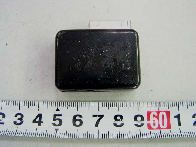
Click to zoom
Application Details
- Equipment Class
- DSS - Part 15 Spread Spectrum Transmitter
- Date of Grant
- Mar 04, 2007
- Application Purpose
- Original Equipment
- Date of Application
- Mar 04, 2007
- Equipment Note
- Bottom Dock BlueTooth Transmitter for iPod
- Frequency Range
- 2402.00000000 - 2480.00000000
- Company
- Scosche Industries Inc
- Country
- United States
Documents & Files
Document Text
Text extracted from the exhibit documents filed with the FCC. Open a document above to read the original.
Users Manual
IPBTT BOTTOM DOCK BLUETOOTH TRANSMITTER FOR IPOD ® IPBTT OVERVIEW Congratulations on your purchase of the IPBTT. This unit incorporates the latest Bluetooth technology for seamless integration with most Bluetooth A2DP enabled products. Before using, please read this manual carefully. ® FEATURES/SPECS Lithium-ion 10 hour Rechargeable Battery (450mAh capacity) Designed with 30-pin iPod bottom dock (All iPods EXCEPT Shuffle, Gen 1, Gen 2) Wireless Range: Up to 30 Feet (10 Meters) Bluetooth® V1.2 Transmitter Power < 3dbm Receiver Sensitivity: -78+4dm Supported Profiles: Advanced Audio Distribution Profile (A2DP) / Audio Video Remote Control Profile (AVRCP) Frequency Range: 2.4Ghz - 2.4835Ghz Dimensions: 55x40x10mm Weight: 16 grams Certifications: FCC Dual RED/BLUE LED Indicators Power Button CHARGING THE BATTERY NOTE: Before using the IPBTT for the first time, charge the battery a full 3 hours. The IPBTT will also charge your iPod battery through the IPBTT power port. 1. Plug the Mini Connector on charger into the charging jack as shown in illustration. 2. Connect USB Cable to an available PC or Laptop USB port. 3. Charge Battery for 3 hours (LED will illuminate RED when charging) 4. The RED LED will turn off when charging is complete. Unplug the IPBTT and enjoy up to 10 hours of use. 5. Purchase wall and car adapters to charge at home and/or on the road. (IPPWR / IP2IN1 - Sold Separately) PAIRING NOTES: The IPBTT transmitter must be paired with a Bluetooth receiving device before use. It is designed for AUTO-Pairing functionality. (Passcode = 0000) Keep the IPBTT and Bluetooth receiving device within a distance of 3ft. (1 Meter) during pairing. Compatible devices must be Bluetooth V1.2 supporting A2DP profile. 1. Power up your Bluetooth® receiving device (such as Scosche wireless headphones or Scosche Bluetooth® receiver) to place it into pairing mode. If needed, consult your Bluetooth® products manual for information on pairing or discovering other Bluetooth® devices. 2. While the Bluetooth® receiver LED is flashing, press and hold the power button on the IPBTT for 3 seconds. The Blue LED indicator light will flash indicating the unit is in pairing mode. 3. Initial pairing can take a few minutes. If pairing is successful, the IPBTT's LED will switch from flashing quickly to flashing slowly. 4. Test the connection by plugging the IPBTT into your iPods bottom dock connection with an audio selection playing. You should hear the audio through your Bluetooth® receiving device. 5. If pairing is not successful, repeat steps 1-4 above. Make sure both devices enter pairing mode at or near the same time. Power off any other Bluetooth® device that you do not intend to pair with the IPBTT as these units may interfere or prevent pairing of other nearby devices. If you still cannot successfully pair two devices, call Tech Support at (1-800-621-3695 Ext.3) Mini Connector Charging Dock PAIRING THE TRANSMITTER WITH BLUETOOTH DEVICES * * * * SCOSCHE UBHP (Not Included) SCOSCHE UBR/UBRH (Not Included) NOT TO SCALE IPBTT If you have any further questions, call our TOLL FREE number: TECHNICAL HELP LINE 1-800-361-3695 Ext.3 12 This device complies with FCC Rules Part 15. Operation is subject to the following two conditions:1) This device may not cause interference, and 2) this device must accept any interference that may be received, including interference that may cause undesired operation. The manufacturer is not responsible for any radio or TV interference caused by unauthorized modification to this equipment. Such modification could void the user's authority to operate the equipment ® ® ® ® IPBTT ® Dual RED/BLUE LED Indicators Power Button OPERATION POWER ON/OFF Press the Power Button for 3 seconds to turn the transmitter ON or OFF. CONNECTION Connect IPBTT to the bottom dock of your iPod. Turn the IPBTT on, then turn on your Bluetooth® headphones or receiving device. Once the two devices are paired, enjoy the audio. REMOTE CONTROL SOURCE FUNCTIONS ONLY when used with a receiving device that also supports the AVCRP profile for remote control functions. ( Scosche Bluetooth® headphones - UBHP) - PLAY/PAUSE Press the power button on your Bluetooth® headphones (or other receiving devices) to PLAY or PAUSE the current track. Do not hold down the power button for for more than 1 second or it may turn off the pwer. (NOTE: Volume control will no longer be controlled through iPod wheel, only through Bluetooth® device controls). - TRACK UP/DOWN 1. Press and hold the volume up button to skip forward to the next track. 2. Press and hold the volume down button to skip back to the beginning of the song. 3. Press and hold the volume down button a second time to skip backward to the previous track. 1. Keep this IPBTT unit away from moisture. Sources of humidity and all types of liquids will corrode electronic circuits. 2. Keep this IPBTT unit away from high heat. Extreme temperatures will shorten the life of electronic circuits and could possibly melt the plastic case. For example, do not store unit in direct sunlight on a vehicle dashboard. 3. Do not attempt to open or repair the transmitter. Non-expert handling may damage it and void any all possibly warranty claims. 4. Don't use harsh chemicals, cleaning solvents or detergents to clean the unit. CARE AND MAINTENANCE LED CHART LED COLOR Blue LED fast blinking Blue LED slow blinking Red ON and/or Blue Slowly Blinking Red LED Solid Red LED off Red LED indicator light is bright Unit drops wireless link Unit loses wireless for no reason IPBTT won't pair with my device No audio heard from transmitter STATUS Pairing Mode Connected with Bluetooth® device Charging and/or connected with Battery is currently charging or LOW Charging Complete Low Battery - Recharge Necessary on battery life Bluetooth® device The connection range varies on the surrounding environment. Range is not guaranteed to be 30 feet in all situations. Range can be reduced by other electronic devices, include c…
Text truncated - open the document above for the full version.
External Photos
External Photos EUT-Front View EUT-Rear View EUT- Side View (1) EUT- Side View (2)
ID Label/Location Info
ID Label/Location Label Location Information Specifications: Text is Black or white in color and is left justified. Labels are printed in indelible ink on permanent adhesive backing or silk-screened onto the EUT or shall be affixed at a conspicuous location on the EUT. Refer to the below arrow.
Internal Photos
Internal Photos EUT-Uncovered View EUT-Inside View EUT-PCB Front View EUT-PCB Rear View
Test Report
Note: This test report is for the customer shown above and their specific product only. It may not be duplicated or used in part without prior written consent from Bay Area Compliance Laboratory Corp. (Shenzhen). This report must not be used by the customer to claim product certification, approval, or endorsement by NVLAP, NIST or any agency of the U.S. Government. FCC PART 15.247 EMI MEASUREMENT AND TEST REPORT For Scosche Industries, Inc. P.O. Box 2901 Oxnard, CA 93034 FCC ID: IKQBTTRNS03 This Report Concerns: Original Report Equipment Type: Bottom Dock Bluetooth Transmitter for iPod Test Engineer: Lisa Zhu Henry Yang Report No.: R0611156 Test Date: 2006-12-04 to 2007-02-15 Report Date: 2007-02-15 Reviewed By: Bonni Baniqued: EMC Manager Prepared By: Bay Area Compliance Laboratory Corp. (Shenzhen) 6/F, the 3rd Phase of WanLi Industrial Building, ShiHua Road, FuTian Free Trade Zone Shenzhen, Guangdong, China Tel: +86-755-33320018 Fax: +86-755-33320008 Scosche Industries, Inc. FCC ID: IKQBTTRNS03 Report # R0611156 Page 2 of 44 FCC Part 15.247 Test Report TABLE OF CONTENTS GENERAL INFORMATION.......................................................................................................................................4 PRODUCT DESCRIPTION FOR EQUIPMENT UNDER TEST (EUT) .....................................................................................4 OBJECTIVE...................................................................................................................................................................4 RELATED SUBMITTAL(S)/GRANT(S).............................................................................................................................4 TEST METHODOLOGY..................................................................................................................................................4 TEST FACILITY.............................................................................................................................................................4 HOST SYSTEM CONFIGURATION LIST AND DETAILS....................................................................................................5 LOCAL SUPPORT EQUIPMENT LIST AND DETAILS........................................................................................................5 EXTERNAL I/O CABLE..................................................................................................................................................5 SYSTEM TEST CONFIGURATION ..........................................................................................................................6 DESCRIPTION OF TEST CONFIGURATION......................................................................................................................6 EUT EXERCISE SOFTWARE..........................................................................................................................................6 SPECIAL ACCESSORIES.................................................................................................................................................6 EQUIPMENT MODIFICATIONS.......................................................................................................................................6 CONFIGURATION OF TEST SETUP.................................................................................................................................7 BLOCK DIAGRAM OF TEST SETUP................................................................................................................................7 SUMMARY OF TEST RESULTS ...............................................................................................................................8 §15.247(b) - RF EXPOSURE ........................................................................................................................................9 LIMIT...........................................................................................................................................................................9 §15.203 - ANTENNA REQUIREMENT....................................................................................................................10 STANDARD APPLICABLE............................................................................................................................................10 ANTENNA CONNECTOR CONSTRUCTION....................................................................................................................10 §15.207 (a) - CONDUCTED EMISSIONS.................................................................................................................11 MEASUREMENT UNCERTAINTY..................................................................................................................................11 EUT SETUP................................................................................................................................................................11 EMI TEST RECEIVER SETUP.......................................................................................................................................12 TEST EQUIPMENT LIST AND DETAILS.........................................................................................................................12 TEST PROCEDURE......................................................................................................................................................12 TEST RESULTS SUMMARY..........................................................................................................................................12 TEST DATA................................................................................................................................................................13 PLOT(S) OF TEST DATA............................................................................................................................…
Text truncated - open the document above for the full version.
Test Setup Photos
Test Setup Photos Conducted Emissions-Front View Conducted Emissions-Side View Radiated Emissions - Front View (30-1000MHz) Radiated Emissions - Rear View (30-1000MHz) Radiated Emissions - Front View (Above 1GHz) Radiated Emissions – Rear View (Above 1GHz)
Contact Information
Applicant
Mark Larson(SR Product Manager)
Technical Contact
Bay Area Compliance LabsHans Mellberg
[email protected]4087329162
1274 Anvilwood Ave. · Sunnyvale · United States
Non-Technical Contact
Bay Area Compliance LabsDouglas Christopher Mendez
[email protected]4087329162
Test Firm
Bay Area Compliance LaboratoryJohn Chan
Technical Specifications
| # | Rule Parts | Frequency Range | Power Output |
|---|---|---|---|
| 1 | 15C | 2.40 GHz - 2.48 GHz | 1.28 mW |
Other Applications from Scosche Industries Inc
IKQLTBTN1
Jul 08, 2026FoundIT Locator Tag
Equipment Class
DTS - Digital Transmission System
IKQLTPAS1
Jul 03, 2026FoundIT Passport
Equipment Class
DTS - Digital Transmission System
IKQLTWAL2
Jun 24, 2026FoundIT Wallet+
Equipment Class
DTS - Digital Transmission System
IKQMRQTR
Apr 10, 2026magicMOUNT RUGGED
Equipment Class
DCD - Part 15 Low Power Transmitter Below 1705 kHz
IKQ-SBTFM5
Apr 09, 2026BT FM Car Charger
Equipment Class
DXX - Part 15 Low Power Communication Device Transmitter