IKQFMTD1Digital FM Transmitter
Scosche Industries Inc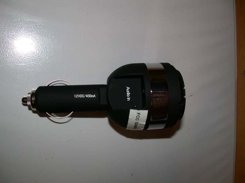
Click to zoom
Application Details
- Equipment Class
- DXX - Part 15 Low Power Communication Device Transmitter
- Date of Grant
- Jan 17, 2008
- Application Purpose
- Original Equipment
- Date of Application
- Jan 16, 2008
- Equipment Note
- Digital FM Transmitter
- Frequency Range
- 88.10000000 - 107.90000000
- Company
- Scosche Industries Inc
- Country
- United States
Documents & Files
Document Text
Text extracted from the exhibit documents filed with the FCC. Open a document above to read the original.
Cover Letter(s)
American Telecommunications Certification Body Inc. 6731 Whittier Ave, McLean, VA 22101 November 27, 2007 RE: ATCB005657 FCC ID: IKQFMTD1 & IC: 6955A-FMTD1 for Scosche Industries Inc. I have a few comments on this Application. Depending on your responses, kindly understand there may be additional comments. 1. Measurements are to be made to the extent practical at the distance specified in the FCC Rules in accordance with Section 15.31(f) of these rules. Please provide justification for performing radiated emissions measurements at 10 meters instead of the 3 meter distance specified in Section 15.239 of the FCC Rules for an FM transmitter operating between 88 and 108 MHz. (For your information – These transmitters have had compliance problems and the FCC just removed them from a Permit But Ask procedure for TCB approval. This means that the FCC would review the application for such a device before the TCB would be allowed to issue a grant of Certification. I suspect that the FCC will not accept measurements at 10 meters for this type of device given the compliance problems that they have been experiencing. Once I receive your justification for making the measurements at 10 meters, I will ask the FCC if they will accept these measurements.) 2. Please confirm that radiated emission measurements were performed to the 10 th harmonic on three channels located near the low, middle and high frequency range of operation for this transmitter. No test data is provided. Please also provide information on the relative noise levels at the 10 meter measurement distance so it can be determined that sufficient signal level is available to measure the harmonic emissions level limit at 10 meters. 3. Please identify the test procedure used to measure emissions from this transmitter. No test procedure was identified in the submitted test procedure. 4. Please confirm that the emissions from the EUT were maximized by placing it in various configurations such as rotated it through 3 orthogonal axes or varying the interconnecting cable positions. 5. Please confirm that the device was investigated to determine that it tuned only within the frequency band of 88.1 MHz to 107.9 MHz during laboratory testing and could not be adjusted to tune outside this band. 6. The block diagram shows that this device operates from 87 to 110 MHz. Both the FCC and IC do not permit operation outside the 88 to 108 MHz band. Please provide a new block diagram that shows compliance with these limits. 7. The test setup photos have two problems: (1) They do not show the EUT. Please provide another photo that shows the EUT being measured. and (2) The test setup does not follow ANSI C63.4 Sections 6.2.1 for use of a table top and Section 6.2.1.2 for arrangement of accessory equipment and their cables. Please justify why this was not followed. 8. Please confirm that the 200 KHz maximum bandwidth was measured with the volume of the MP3 player turned up to maximum or a level that maximized the emission bandwidth. Page 2 November 27, 2007 9. The operational description and the schematic both show that this transmitter operates with either only 8 channels or with all channels between 88.1 and 107.9 MHz (spaced 200 KHz apart). Either retest the device for 8 channel operation compliance or correct these incorrect exhibits. 10. Some of the plots provided between 30 and 1000 MHz appear to have no relation to the table data that follows each plot. For example, on page 12 the Mid Channel Vertical plot shows a peak emission level that is less than 30 dBuV/m but the table below it lists a corrected level of 36.4 dBuV/m and a recorded level of 52.4 dBuV/m. Both of these values are average values according to the note. Please explain the relationship of the plots to the tabular data that follows. 11. The contact person listed on the FCC Website for Scosche Industries is Peter Butcher. However, Jack DeBiasio has signed the FCC letters for confidentiality and agency. Either have Peter Butcher submit a letter authorizing Jack DeBiasio to sign these letters for Scosche Industries or change the contact name on the FCC Website to Jack DeBiasio. For help changing the contact name on the FCC Website, you can email Ms. Marianne Bosley at [email protected]. 12. Please measure the 99 % bandwidth using the test procedure attached and submit the results in an amended test report. The bandwidth in the test report was not measured in accordance with IC accepted test procedures for measuring the required 99 % bandwidth. 13. Please submit an REL letter for the IC application. You can find a sample REL letter attached to the ATCB application for IC on our Website. 14. Please submit a letter requesting confidentiality of exhibits that are submitted to IC. All exhibits are uploaded to IC beginning in September of this year. A confidentiality request letter should be submitted to IC to protect Scosche Industries. A sample letter is attached to the ATCB application for IC on our Website. 15. Please provide an appendix A and B of RSS-102 in accordance with Section 5.1(e) of RSP- 100 Issue 9 dated June 2007. 16. Please provide a new IC label that does not have the word “Number” between the letters “IC” and the colon (: ) in the IC label. Section 5.2 of RSS-Gen Issue 2 dated June 2007 requires the label to be IC: followed by the company number and UPN number. The word “Number” must not be in the IC label. Richard Fabina Examining Engineer mailto: [email protected] The items indicated above must be submitted before processing can continue on the above referenced application. Failure to provide the requested information may result in application Page 3 November 27, 2007 termination. Correspondence should be considered part of the permanent submission and may be viewed from the Internet after a Grant of Equipment Authorization is issued. Please do not respond to this correspondence using the email reply button. In order for your response to be processed expeditiously, you …
Text truncated - open the document above for the full version.
Cover Letter(s)
1601 FM 1460, Suite B Round Rock, TX 78664 e-mail: [email protected] (512)244-3371 Fax: (512)244-1846 December 18, 2007 FCC ID: IKQFMTD1 IC: 6955A-FMTD1 In response to your comments regarding the application for certification of the device referenced above please find our response below: 1.) Measurements are to be made to the extent practical at the distance specified in the FCC Rules in accordance with Section 15.31(f) of these rules. Please provide justification for performing radiated emissions measurements at 10 meters instead of the 3 meter distance specified in Section 15.239 of the FCC Rules for an FM transmitter operating between 88 and 108 MHz. (For your information – These transmitters have had compliance problems and the FCC just removed them from a Permit But Ask procedure for TCB approval. This means that the FCC would review the application for such a device before the TCB would be allowed to issue a grant of Certification. I suspect that the FCC will not accept measurements at 10 meters for this type of device given the compliance problems that they have been experiencing. Once I receive your justification for making the measurements at 10 meters, I will ask the FCC if they will accept these measurements.) The test was performed again at 3 meters and the report has been updated with the new data. 2.) Please confirm that radiated emission measurements were performed to the 10th harmonic on three channels located near the low, middle and high frequency range of operation for this transmitter. No test data is provided. Please also provide information on the relative noise levels at the 10 meter measurement distance so it can be determined that sufficient signal level is available to measure the harmonic emissions level limit at 10 meters. The emissions measurements were performed to the 10 th harmonic. The testing was performed again at 3 meters. The report has been updated with the new data. 3.) Please identify the test procedure used to measure emissions from this transmitter. No test procedure was identified in the submitted test procedure. ANSI C63.4. 4.) Please confirm that the emissions from the EUT were maximized by placing it in various configurations such as rotated it through 3 orthogonal axes or varying the interconnecting cable positions. Yes, the emissions were maximized from the device by placing it in 3 orthogonal axes. 5.) Please confirm that the device was investigated to determine that it tuned only within the frequency band of 88.1 MHz to 107.9 MHz during laboratory testing and could not be adjusted to tune outside this band. The device is not capable of being tuned outside of the 88.1-107.9 MHz band. 6.) The block diagram shows that this device operates from 87 to 110 MHz. Both the FCC and IC do not permit operation outside the 88 to 108 MHz band. Please provide a new block diagram that shows compliance with these limits. The block diagram has been updated with the correct values. The latest exhibit will be uploaded. 7.) The test setup photos have two problems: (1) They do not show the EUT. Please provide another photo that shows the EUT being measured. and (2) The test setup does not follow ANSI C63.4 Sections 6.2.1 for use of a table top and Section 6.2.1.2 for arrangement of accessory equipment and their cables. Please justify why this was not followed. The device was retested utilizing the requirements of ANSI C63.4. The revised test report will be uploaded. 8.) Please confirm that the 200 KHz maximum bandwidth was measured with the volume of the MP3 player turned up to maximum or a level that maximized the emission bandwidth. The device was tested with the volume at maximum to capture the worst case frequency deviation. 9.) The operational description and the schematic both show that this transmitter operates with either only 8 channels or with all channels between 88.1 and 107.9 MHz (spaced 200 KHz apart). Either retest the device for 8 channel operation compliance or correct these incorrect exhibits. An 8 channel device will be filed in a separate application. The device is configured for either 8 channel operation or digital operation so that it can be tuned to any channel in the 88.1-107.9 MHz band. The mode is set at the factory and is not accessible to the user. The 8 channel device will be filed as the FMT1. 10.) Some of the plots provided between 30 and 1000 MHz appear to have no relation to the table data that follows each plot. For example, on page 12 the Mid Channel Vertical plot shows a peak emission level that is less than 30 dBuV/m but the table below it lists a corrected level of 36.4 dBuV/m and a recorded level of 52.4 dBuV/m. Both of these values are average values according to the note. Please explain the relationship of the plots to the tabular data that follows. The device was manually retested at 3 meters. No plots will be provided in the updated test report. 11.) The contact person listed on the FCC Website for Scosche Industries is Peter Butcher. However, Jack DeBiasio has signed the FCC letters for confidentiality and agency. Either have Peter Butcher submit a letter authorizing Jack DeBiasio to sign these letters for Scosche Industries or change the contact name on the FCC Website to Jack DeBiasio. For help changing the contact name on the FCC Website, you can email Ms. Marianne Bosley at [email protected] . A cover letter has been generated and will be uploaded. 12.) Please measure the 99 % bandwidth using the test procedure attached and submit the results in an amended test report. The bandwidth in the test report was not measured in accordance with IC accepted test procedures for measuring the required 99 % bandwidth. The measurements were taken and the data has been incorporated into the revised report. 13.) Please submit an REL letter for the IC application. You can find a sample REL letter attached to the ATCB application for IC on our Website. A letter has been generated and will be uploaded. 14.) Please submit a letter …
Text truncated - open the document above for the full version.
Test Report
Professional Testing (EMI), Inc. Project 08170-10 Page 1 of 16 Project Number: 08170-10 Prepared for: Scosche Industries, Inc. 1550 Pacific Ave Oxnard, CA 93033 By Professional Testing (EMI), Inc. 1601 FM 1460, Suite B Round Rock, Texas 78664 December 2007 CERTIFICATION Electromagnetic Interference Test Report Scosche Industries, Inc. FMTD1 Professional Testing (EMI), Inc. Project 08170-10 Page 2 of 16 Table of Contents Title Page .........................................................................................................................................1 Table of Contents .............................................................................................................................2 Certificate of Compliance ................................................................................................................3 1.0 EUT Description ..................................................................................................................4 1.1 Applicable Documents.....................................................................................................4 1.2 EUT Operation.................................................................................................................4 2.0 Electromagnetic Emissions Testing.....................................................................................5 2.1 Radiated Emissions Measurements .................................................................................5 2.1.1 Test Procedure .........................................................................................................5 2.1.2 Test Criteria .............................................................................................................6 2.1.3 Test Results ..............................................................................................................6 3.0 Occupied Bandwidth Measurements ...................................................................................7 3.1 Test Procedure .................................................................................................................7 3.2 Test Criteria .....................................................................................................................7 3.3 Test Results ......................................................................................................................7 4.0 Antenna Requirement ..........................................................................................................7 4.1 Evaluation Procedure .......................................................................................................7 4.2 Evaluation Criteria ...........................................................................................................8 4.3 Evaluation Results ...........................................................................................................8 5.0 Modifications to Equipment ................................................................................................8 6.0 List of Test Equipment.........................................................................................................8 FIGURES Figure 1 Radiated Emissions Test Setup .........................................................................................9 APPENDICES Appendix A Emissions Data ..........................................................................................................10 THIS REPORT SHALL NOT BE REPRODUCED EXCEPT IN FULL, WITHOUT THE WRITTEN APPROVAL OF PROFESSIONAL TESTING (EMI), INC. Professional Testing (EMI), Inc. Project 08170-10 Page 3 of 16 Applicant: Scosche Industries, Inc. Applicant’s Address: 1550 Pacific Ave Oxnard, CA 93033 FCC ID: IKQFMTD1 IC Number 6955A-FMTD1 Project Number: 08170-10 Test Dates: December 06, 2007 I, Jason Anderson, for Professional Testing (EMI), Inc., being familiar with the FCC and IC rules and test procedures have reviewed the test setup, measured data and this report. I believe them to be true and accurate. The Scosche Industries, Inc., FMTD1 was tested to and found to be in compliance with FCC Part 15 Subpart C and IC RSS 210 for an Intentional Radiator. The highest emissions generated by the above equipment are listed below: Frequency (MHz) Level (dBμV/m) Limit (dBμV/m) Margin (dB) Fundamental 88.1 47.9.0 48 -0.1 Spurious 335 42.7 46 -3.3 Occupied Bandwidth 174.7 kHz Jason Anderson Director of Testing Services This report has been reviewed and accepted by Scosche Industries, Inc. The undersigned is responsible for ensuring that Scosche Industries, Inc., FMTD1 will continue to comply with the FCC and IC rules. Certificate Of Compliance Professional Testing (EMI), Inc. Project 08170-10 Page 4 of 16 1.0 EUT Description The Scosche Industries, Inc. FMTD1 enables you to play your digital music through your FM radio. The FMTD1 wirelessly broadcasts the audio signal to your FM radio in your car. No additional wiring is necessary. The broadcast frequency is fully adjustable throughout the FM band in 200 kHz steps from 88.1 to 107.9 MHz. The system tested consisted of the following: Manufacturer & Model FCC Number IC Number Scosche Industries, Inc., FMTD1 IKQFMTD1 6955A-FMTD1 1.1 Applicable Documents Guidelines FCC Rule Parts Part 15 IC Rule Parts Transmitter Characteristics 15.239 RSS-210 A2.8 Spurious Radiated Power 15.205, 15.209, 15.239 RSS-210 2.7 Table 2 Antenna Requirement 15.203 RSS-Gen 7.1.4 1.2 EUT Operation The EUT was operated in continuous transmit mode at max power frequency modulated with music generated from an MP3 player to measure fundamental, harmonics, and spurious radiation. 1.3 Applicable Documnets ANSI C63.4 American National Standard for Methods of Measurement of Radio-Noise Emissions from Low Voltage Electrical and Electronic Equipment. 2003 47 CFR Part 15 – Radio Frequency Devices Subpart C RSS-210 Issue 7 Low-power Licence-exempt Radiocommunication Devices (All Frequency Bands)…
Text truncated - open the document above for the full version.
Contact Information
Applicant
Mark Larson(SR Product Manager)
Technical Contact
Professional Testing (EMI) Inc.Jason Anderson
[email protected]512-244-3371
1601 FM 1460 Suite B · Round Rock, Texas · United States
Non-Technical Contact
Professional Testing (EMI) Inc.Annette Rice
[email protected]512-244-3371
Test Firm
Professional Testing (EMI), Inc.Michael Royer
Technical Specifications
| # | Rule Parts | Frequency Range | Power Output |
|---|---|---|---|
| 1 | 15C | 88.1 MHz - 107.9 MHz | - |
Other Applications from Scosche Industries Inc
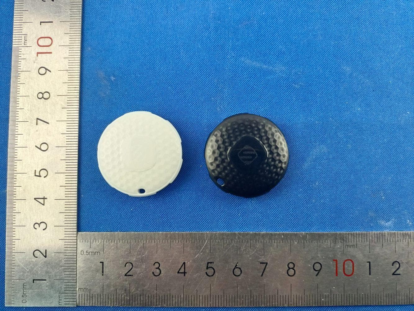
IKQLTBTN1
Jul 08, 2026FoundIT Locator Tag
Equipment Class
DTS - Digital Transmission System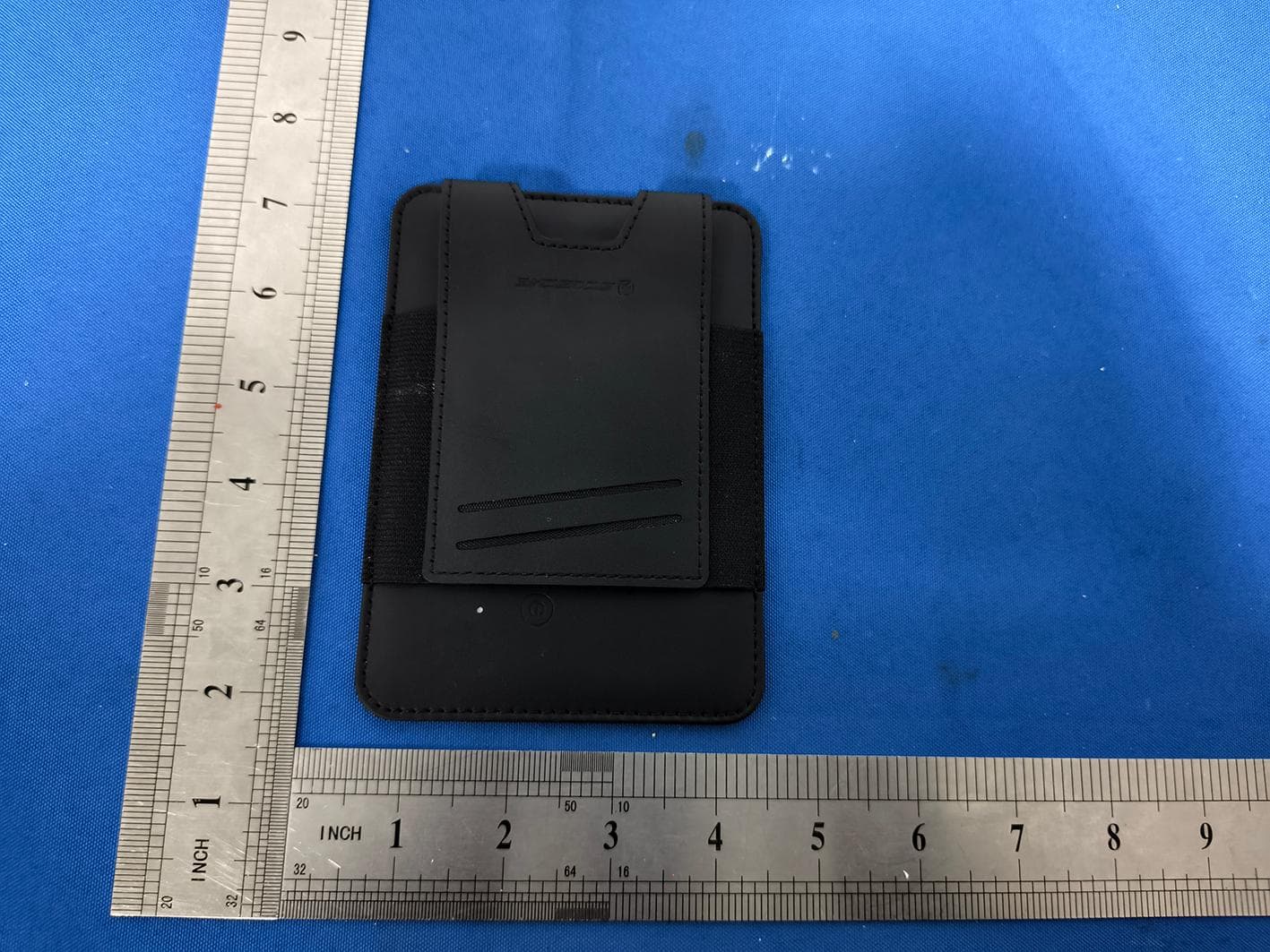
IKQLTPAS1
Jul 03, 2026FoundIT Passport
Equipment Class
DTS - Digital Transmission System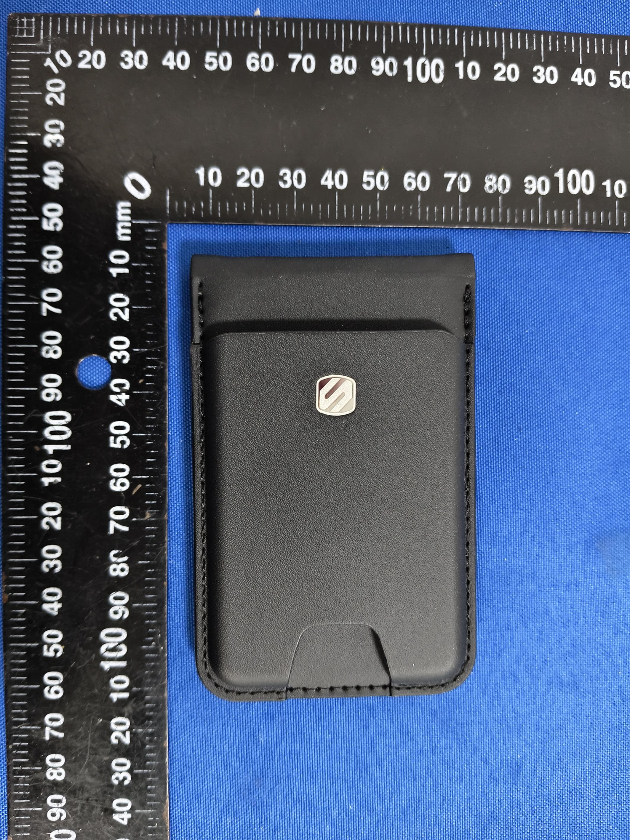
IKQLTWAL2
Jun 24, 2026FoundIT Wallet+
Equipment Class
DTS - Digital Transmission System
IKQMRQTR
Apr 10, 2026magicMOUNT RUGGED
Equipment Class
DCD - Part 15 Low Power Transmitter Below 1705 kHz
IKQ-SBTFM5
Apr 09, 2026BT FM Car Charger
Equipment Class
DXX - Part 15 Low Power Communication Device Transmitter