IKQIPTRNSXFM Audio Transmitter
Scosche Industries Inc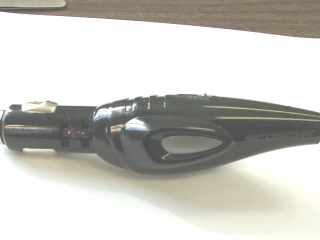
Click to zoom
Application Details
- Equipment Class
- DXX - Part 15 Low Power Communication Device Transmitter
- Date of Grant
- Jul 27, 2006
- Application Purpose
- Original Equipment
- Date of Application
- Jul 27, 2006
- Equipment Note
- FM Audio Transmitter
- Frequency Range
- 88.10000000 - 107.70000000
- Company
- Scosche Industries Inc
- Country
- United States
Documents & Files
Document Text
Text extracted from the exhibit documents filed with the FCC. Open a document above to read the original.
Users Manual
IPTRNSX OPERATING INSTRUCTIONS CONNECTING THE IPTRNSX: 1. Plug the IPTRNSX into the cigarette lighter or 12V DC power socket in your dash. A Blue LED will illuminate indicating the IPTRNSX has power. A. For iPod media players, use the cable with the iPod dock connector. Plug the docking cable into the bottom of the iPod then plug the Mini USB end of the cable into the back of the IPTRNSX body. This cable will also charge the iPod battery when connected. B. For MP3 media players, use the cable with the 3.5mm headphone plug. Insert the 3.5mm plug into the headphone jack of the portable device then plug the Mini USB end of the cable into the back of the IPTRNSX body. TUNING THE IPTRNSX: 1. Once the cable connections are made, choose a frequency range. The L/H switch on the bottom of the IPTRNSX body selects either a Low or High set of frequencies. The Low (L) frequencies are printed along the left of the slide switch on the IPTRNSX and begin with 88.1Mhz. The High (H) frequencies are printed along the right of the slide switch and begin with 107.1Mhz. HINT: Scan your FM radio in the frequency ranges from 88.1 to 88.7Mhz (L) and 107.1-107.7 Mhz (H). Look for existing radio stations. Select a range with the LEAST number of local radio station signals. 2. Tune your FM radio to the corresponding station selected on the top of the IPTRNSX unit. 3. Power up and play your iPod / MP3 media player. You should hear the sound from your iPod/MP3 player through your stereo speakers. Adjust the volume on your stereo, not the portable player. For future use, set the selected station to an FM radio preset station button. If there is excess/unwanted static, then select a different frequency on the IPTRNSX and change the radio to match the new frequency. IPTRNSX OPERATING INSTRUCTIONS CONNECTING THE IPTRNSX: 1. Plug the IPTRNSX into the cigarette lighter or 12V DC power socket in your dash. A Blue LED will illuminate indicating the IPTRNSX has power. A. For iPod media players, use the cable with the iPod dock connector. Plug the docking cable into the bottom of the iPod then plug the Mini USB end of the cable into the back of the IPTRNSX body. This cable will also charge the iPod battery when connected. B. For MP3 media players, use the cable with the 3.5mm headphone plug. Insert the 3.5mm plug into the headphone jack of the portable device then plug the Mini USB end of the cable into the back of the IPTRNSX body. TUNING THE IPTRNSX: 1. Once the cable connections are made, choose a frequency range. The L/H switch on the bottom of the IPTRNSX body selects either a Low or High set of frequencies. The Low (L) frequencies are printed along the left of the slide switch on the IPTRNSX and begin with 88.1Mhz. The High (H) frequencies are printed along the right of the slide switch and begin with 107.1Mhz. HINT: Scan your FM radio in the frequency ranges from 88.1 to 88.7Mhz (L) and 107.1-107.7 Mhz (H). Look for existing radio stations. Select a range with the LEAST number of local radio station signals. 2. Tune your FM radio to the corresponding station selected on the top of the IPTRNSX unit. 3. Power up and play your iPod / MP3 media player. You should hear the sound from your iPod/MP3 player through your stereo speakers. Adjust the volume on your stereo, not the portable player. For future use, set the selected station to an FM radio preset station button. If there is excess/unwanted static, then select a different frequency on the IPTRNSX and change the radio to match the new frequency. FCC STATEMENT: “Modification not authorized by the manufacturer may void users authority to operate this device.” NOTE: This equipment has been tested and found to comply with the limits for a class B digital device, pursuant to Part 15 of the FCC Rules. These limits are designed to provide reasonable protection against harmful interference in a residential installation. This equipment generates, uses and can radiate radio frequency energy and, if not installed and used in accordance with the instructions, may cause harmful interference to radio communications. However, there is no guarantee that interference will not occur in a particular installation. If this equipment does cause harmful interference to radio or television reception, which can be determined by turning the equipment off and on, the user is encouraged to try to correct the interference by one or more of the following measures: * Reorient or relocate the receiving antenna. * Increase the separation between the equipment and receiver. * Connect the equipment into an outlet on a circuit different from that to which the receiver is connected. * Consult the dealer or an experienced radio/TV technician for help. FCC ID: IKQIPTRNSX MADE IN CHINA This device complies with part 15 of the FCC Rules. Operation is subject to the following two conditions: (1) this device may not cause harmful interference, and (2) this device must accept any interference received, including interference that may cause undesired operation.
Cover Letter(s)
Scott McCutchan From: Scott McCutchan [[email protected]] Sent: Friday, July 14, 2006 6:07 PM To: '[email protected]' Subject: FCC ID: IKQIPTRNSX 7/14/2006 Mr. Fujimoto: In order for processing of this permissive change application (FCC ID: IKQIPTRNSX) to continue, the following issue(s) will have to be addressed: 1) According to the general report summary, radiated emissions test procedures, and transducer tables of the test report, the frequency range investigated did not include frequencies above 1 GHz, as should be the case for this device. 2) Please indicate compliance with the voltage variation requirements of section 15.31 (e). 3) The block diagram submitted is not sufficient, per section 2.1033(b)(5). Please submit an updated diagram. The item(s) indicated above must be submitted before processing can continue on the above referenced application. Failure to provide the requested information within 60 days of the original e-mail date may result in application dismissal and forfeiture of the filing fee. Also, please note that partial responses increase processing time and should not be submitted. Please upload responses and/or exhibits to the electronic filing website. Your correspondence number is IKQIPTRNSX-1. Best regards, Scott McCutchan Operations Manager Compatible Electronics TCB 114 Olinda Drive Brea, CA 92823 (714) 579-0500 Fax (714) 579-1850
Cover Letter(s)
Correspondence by Project Project Number: Correspondence NumberMemo IKQIPTRNSX-1 Mr. McCutchan, In response to your e-mail reference FCC ID: IKQIPTRNSX I am submitting the following documents: 1) A Copy of the report (number A60428F1) which includes the radiated test procedures, transducer tables and data which clearly demonstrate the the frequencies above 1 GHz which were tested. Please see page 4, appendix D and appendix E. 2) Compliance with section 15.31(e) is indicated in the aforementioned report on Page 4 as well as in the conclusion on page 17. 3) I am submitting a new block diagram with the clock frequency clearly indicated. Last I am submitting a letter of confidentiality, which may have been overlooked at the time of the original submittal. If you have any further questions, please feel free to contact me. Best Regards, Ruby Hall Lab Manager Compatible Electronics (Agoura) 2337 Troutdale DRive Agoura, CA 91301 (818) 597-0600 Fax (818) 597-1187 1149527885
External Photos
FCC ID: IKQIPTRNSX TOP VIEW FCC ID: IKQIPTRNSX LEFT SIDE FCC ID: IKQIPTRNSX RIGHT SIDE FCC ID: IKQIPTRNSX BOTTOM VIEW
ID Label/Location Info
FCC ID will be silk screened on part. Label is for placement only. FCC ID: IKQIPTRNSX
Internal Photos
FCC ID: IKQIPTRNSX COVER REMOVED FCC ID: IKQIPTRNSX PC BOARD SIDE 1 FCC ID: IKQIPTRNSX PC BOARD SIDE 2 FCC ID: IKQIPTRNSX PC BOARD SIDE 2 CLOSE UP RIGHT SIDE FCC ID: IKQIPTRNSX PC BOARD SIDE 2 CLOSE UP LEFT SIDE
Test Report
FCC ID: IKQIPTRNSX Report Number: A60428F1 2337 TROUTDALE DRIVE, AGOURA, CALIFORNIA, 91301 • PH: (818) 597-0600 FX: (818) 597-1187 Page 1 of 17 FCC PART 15, SUBPART C TEST REPORT for FM AUDIO TRANSMITTER M/N: IPTRNSX FCC ID: IKQIPTRNSX Prepared for SCOSCHE INDUSTRIES INC. 1550 PACIFIC AVENUE OXNARD, CA 93033 Prepared by: _____________________ REYNALD O. RAMIREZ Approved by: ____________________ RUBY A. HALL COMPATIBLE ELECTRONICS INC. 2337 TROUTDALE DRIVE AGOURA, CALIFORNIA 91301 (818) 597-0600 DATE: MAY 5, 2006 REPORT APPENDICES TOTAL BODY A B C D E PAGES 17 2 2 2 13 18 54 This report shall not be reproduced except in full, without the written approval of Compatible Electronics. FCC ID: IKQIPTRNSX Report Number: A60428F1 2337 TROUTDALE DRIVE, AGOURA, CALIFORNIA, 91301 • PH: (818) 597-0600 FX: (818) 597-1187 Page 2 of 17 TABLE OF CONTENTS Section / Title PAGE GENERAL REPORT SUMMARY 4 SUMMARY OF TEST RESULTS 4 1. PURPOSE 5 2. ADMINISTRATIVE DATA 6 2.1 Location of Testing 6 2.2 Traceability Statement 6 2.3 Cognizant Personnel 6 2.4 Date Test Sample was Received 6 2.5 Disposition of the Test Sample 6 2.6 Abbreviations and Acronyms 6 3. APPLICABLE DOCUMENTS 7 4. DESCRIPTION OF TEST CONFIGURATION 8 4.1 Description of Test Configuration - EMI 8 4.1.1 Photograph of Test Configuration - EMI 8 4.1.2 Cable Construction and Termination 9 5. LISTS OF EUT, ACCESSORIES AND TEST EQUIPMENT 10 5.1 EUT and Accessory List 10 5.2 EMI Test Equipment 11 6. TEST SITE DESCRIPTION 12 6.1 Test Facility Description 12 6.2 EUT Mounting, Bonding and Grounding 12 7. TEST PROCEDURES 13 7.1 RF Emissions 13 7.1.1 Conducted Emissions Test 13 7.1.2 Radiated Emissions Test 14 7.1.3 RF Emissions Test Results 15 7.1.4 Sample Calculations 16 8. TEST PROCEDURE DEVIATIONS 17 9. CONCLUSIONS 17 FCC ID: IKQIPTRNSX Report Number: A60428F1 2337 TROUTDALE DRIVE, AGOURA, CALIFORNIA, 91301 • PH: (818) 597-0600 FX: (818) 597-1187 Page 3 of 17 LIST OF APPENDICES APPENDIX TITLE A Laboratory Accreditations B Modifications to the EUT C Additional Models Covered Under This Report D Diagrams, Charts and Photos • Test Setup Diagrams • Antenna and Amplifier Gain Factors • Radiated Emissions Photos E Data Sheets LIST OF FIGURES FIGURE TITLE 1 Plot Map And Layout of Test Site FCC ID: IKQIPTRNSX Report Number: A60428F1 2337 TROUTDALE DRIVE, AGOURA, CALIFORNIA, 91301 • PH: (818) 597-0600 FX: (818) 597-1187 Page 4 of 17 GENERAL REPORT SUMMARY This electromagnetic emission report is generated by Compatible Electronics Inc., which is an independent testing and consulting firm. The test report is based on testing performed by Compatible Electronics personnel according to the measurement procedures described in the test specifications given below and in the "Test Procedures" section of this report. The measurement data and conclusions appearing herein relate only to the sample tested and this report may not be reproduced in any form except in full, without the written permission of Compatible Electronics. This report must not be used to claim product endorsement by NVLAP, NIST or any other agency of the U.S. Government. Device Tested: FM Audio Transmitter Model Number: IPTRNSX SN: None Product Description: This is an FM Audio Transmitter. Modifications: The EUT was not modified during the testing. Manufacturer: Scosche Industries Inc. 1550 Pacific Avenue Oxnard, CA 93033 Test Date: April 28, 2006 Test Specifications: EMI requirements FCC CFR Title 47, Part 15 Subpart A, B and C sections 15.31 (e), 15.109, 15.205, 15.209 and 15.239 Test Procedure: ANSI C63.4: 2003. SUMMARY OF TEST RESULTS TEST DESCRIPTION RESULTS 1 Conducted RF Emissions, 150 kHz - 30 MHz. This is a DC powered device that does not plug into AC Mains therefore this test was deemed unnecessary. 2 Radiated RF Emissions, 9 kHz – 1077 MHz. Complies with the limits of FCC CFR Title 47, Part 15 Subpart C 15.205, 15.209 and 15.239 and the requirements of 15.31(e). FCC ID: IKQIPTRNSX Report Number: A60428F1 2337 TROUTDALE DRIVE, AGOURA, CALIFORNIA, 91301 • PH: (818) 597-0600 FX: (818) 597-1187 Page 5 of 17 1. PURPOSE This document is a qualification test report based on the Electromagnetic Interference (EMI) tests performed on the FM Audio Transmitter Model Number: IPTRNSX. The EMI measurements were performed according to the measurement procedure described in ANSI C63.4: 2003. The tests were performed in order to determine whether the electromagnetic emissions from the equipment under test, referred to as EUT hereafter, are within the specification limits defined in FCC CFR Title 47, Part 15 Subpart A (15.31e), Subpart B, 15.109 Subpart C 15.205, 15.209 and 15.239. FCC ID: IKQIPTRNSX Report Number: A60428F1 2337 TROUTDALE DRIVE, AGOURA, CALIFORNIA, 91301 • PH: (818) 597-0600 FX: (818) 597-1187 Page 6 of 17 2. ADMINISTRATIVE DATA 2.1 Location of Testing The EMI tests described herein were performed at the test facility of Compatible Electronics, 2337 Troutdale Drive, Agoura, California 91301. 2.2 Traceability Statement The calibration certificates of all test equipment used during the test are on file at the location of the test. The calibration is traceable to the National Institute of Standards and Technology (NIST). 2.3 Cognizant Personnel Scosche Industries Inc. Jack DeBiasio Project Manager Compatible Electronics Inc. Reynald O. Ramirez Sr. Test Engineer Ruby A. Hall Lab Manager 2.4 Date Test Sample was Received The test sample was received on April 28, 2006. 2.5 Disposition of the Test Sample The test sample remains at Compatible Electronics Inc. 2.6 Abbreviations and Acronyms The following abbreviations and acronyms may be used in this document. RF Radio Frequency EMI Electromagnetic Interference EUT Equipment Under Test P/N Part Number S/N Serial Number HP Hewlett Packard ITE Information Technology Equipment CML Corrected Meter Limit LISN Line Impedance Stabilization Network FCC ID: IKQIPTRNSX Report Number: A60428F1 2337 TROUTDALE DRIVE, AGOURA, CALIFORNIA, 91301 • PH: (818) 597-0600 FX:…
Text truncated - open the document above for the full version.
Test Setup Photos
FCC ID: IKQIPTRNSX FRONT VIEW FCC ID: IKQIPTRNSX REAR VIEW
Contact Information
Applicant
Mark Larson(SR Product Manager)
Technical Contact
Compatible ElectronicsReynald O Ramirez
[email protected]818-597-0600
2337 Troutdale Drive · Agoura, California · United States
Test Firm
Compatible ElectronicsRuby Hall
Technical Specifications
| # | Rule Parts | Frequency Range | Power Output |
|---|---|---|---|
| 1 | 15C | 88.1 MHz - 107.7 MHz | - |
Other Applications from Scosche Industries Inc
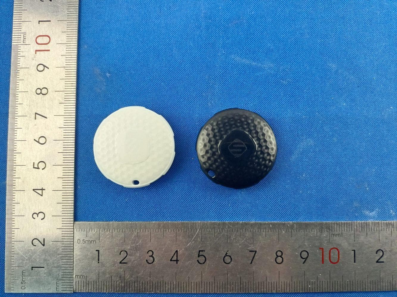
IKQLTBTN1
Jul 08, 2026FoundIT Locator Tag
Equipment Class
DTS - Digital Transmission System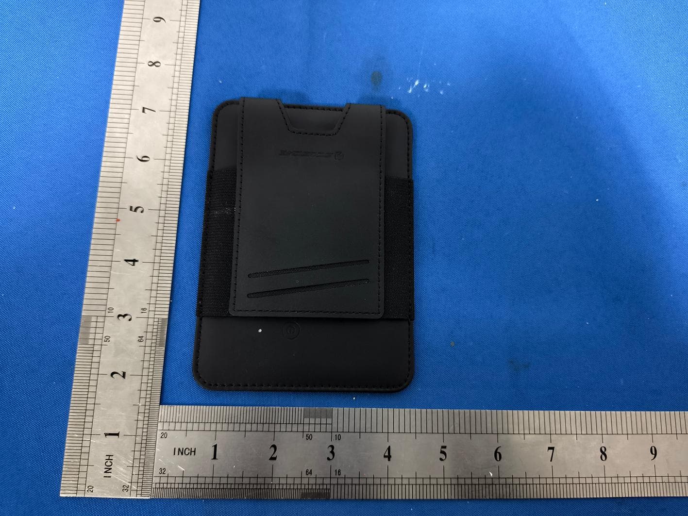
IKQLTPAS1
Jul 03, 2026FoundIT Passport
Equipment Class
DTS - Digital Transmission System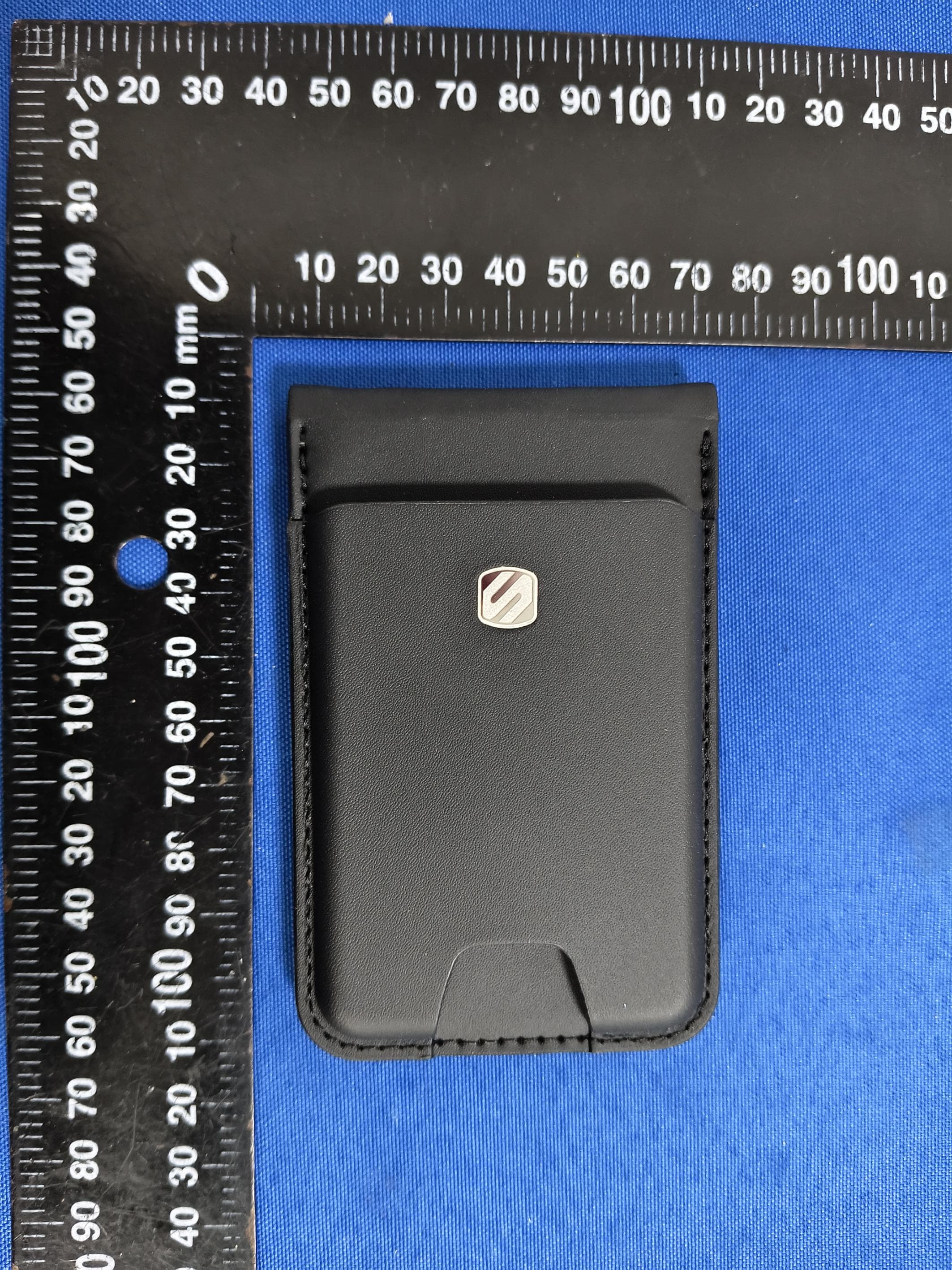
IKQLTWAL2
Jun 24, 2026FoundIT Wallet+
Equipment Class
DTS - Digital Transmission System
IKQMRQTR
Apr 10, 2026magicMOUNT RUGGED
Equipment Class
DCD - Part 15 Low Power Transmitter Below 1705 kHz
IKQ-SBTFM5
Apr 09, 2026BT FM Car Charger
Equipment Class
DXX - Part 15 Low Power Communication Device Transmitter