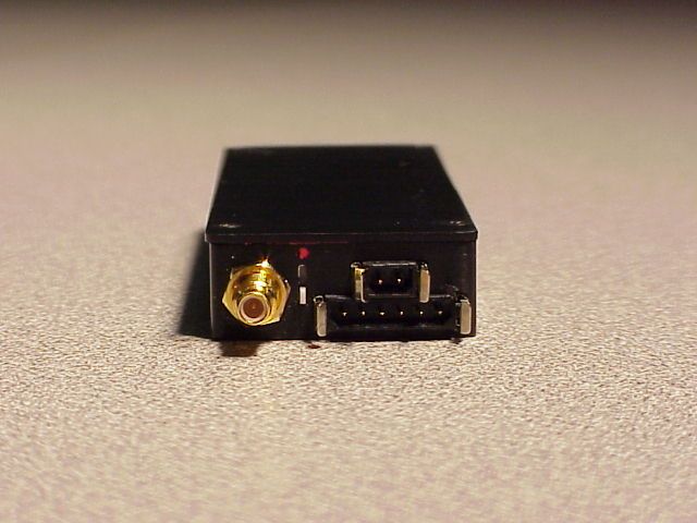
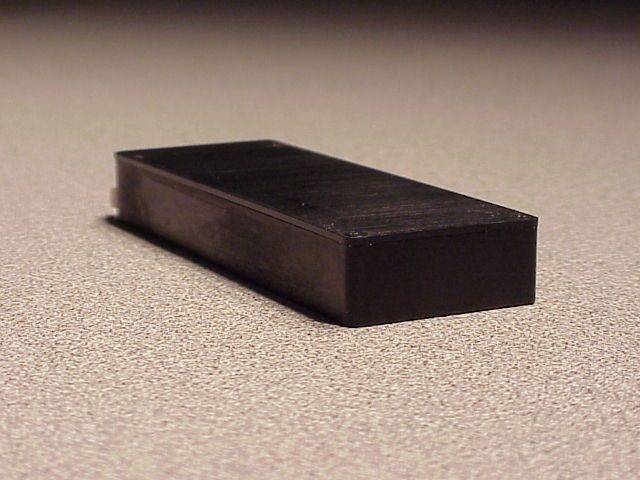
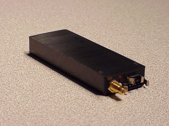
IP9751VLaw Enforcement Surveillance Transmitter
Tactical Technologies Inc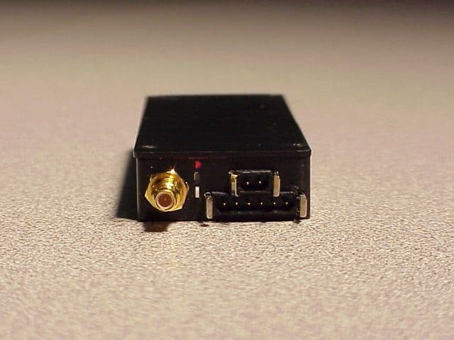
Click to zoom
Application Details
- Equipment Class
- LMS - Part 90 Location & Monitoring Transmitter
- Date of Grant
- Dec 01, 2002
- Application Purpose
- Original Equipment
- Date of Application
- Aug 29, 2002
- Equipment Note
- Law Enforcement Surveillance Transmitter
- Frequency Range
- 150.00000000 - 174.00000000
- Company
- Tactical Technologies Inc
- Country
- United States
Documents & Files
Document Text
Text extracted from the exhibit documents filed with the FCC. Open a document above to read the original.
Users Manual
© Tactical Technologies Inc The JOEY TRANSCORDER Synthesized Voice Transmitter PLUS Solid State Recorder All-in-one Package CTR-751/V OPERATING INSTRUCTIONS Rev 1c DESCRIPTION The Tactical Technologies Inc. Model CTR-751/V series ("Joey") is a 1 channel 1/2 Watt VHF-FM synthesized voice transmitter, combined with a solid state recorder. The transmitter and recorder combination ("Transcorder") requires 9 volts DC for its power supply, utilizes an external antenna for the transmitter, and a single microphone for both the transmitter and recorder operations. It can be optionally equipped with a scramble for added security. The CTR-751 series transmitter operating frequencies are programmed via an open serial port on an IBM compatible PC. The transmitter's firmware is compatible with ANY vintage IBM compatible PC's communications program - such as Microsoft's Hyperterminal. The recorder can use the same PC serial port. Proprietary software for recorder operations is included. You can also program the transmitter in the CST-751/V direct from the panel of a Citation 20 Synthesized Intelligence Receiver Recorder Kit! Features of the Joey Solid State Recorder include: Easily concealable, Multiple MONO recordings, Very low power consump- tion, 2 Selectable sampling rates of 8 or 11 kHz, ability to download individual recordings, RS232 interface to standard PC serial port, raw data download with audit trail identifiers and checksum information. The Joey recorder is also available with either a 64Mbyte or 128Mbyte memory chip which respectively yields record times from 100 minutes to 440 minutes. The supplied instructions are for the Window 95, 98, or XP operating systems. The Joey TM Transcorder TM Voice Transmitter and Solid State Recorder All-In-One Unit TRANSCORDER OPERATION SETUP 1.) Connect the external antenna to the CTR-751 by inserting the male end of the SMC type antenna connector on the transmitter to the female connector end on the wire antenna. Twist the connector clockwise to tighten (HAND TIGHT ONLY!). 2.) Connect the Microphone. Determine which of the two supplied microphone configurations are best for your application: the long leadwire microphone or the short/stubby microphone. Connect the microphone by inserting the female end of the friction-locking 2 pin connector on the microphone cable into the male connector found on the CTR-751. This connector is keyed for proper installation. Push the connectors firmly together. 3.) Connect the power lead to the transmitter. Connect the 9 VDC battery lead by inserting the female end of the friction-locking 6 pin connector on the power cable into the male connector found on the CTR-751. This connector is keyed for proper installation. Push the connectors firmly together. 4.) Any 9 VDC power supply (batteries, regulated supply, etc.) can be applied to the CTR-751. When using disposable batteries, always use either Alkaline or Lithium cells. Lithium cells are recommended for longer operating life. NOTE: DO NOT APPLY 12 VDC DIRECTLY TO THIS UNIT. NOTE: THE CST-751 IS REVERSE POLARITY PROTECTED, HOWEVER PLEASE BY SURE TO CONNECT THE + AND - LEADS TO YOUR POWER SUPPLY CORRECTLY FOR PROPER OPERATION OF THE TRANSMITTER. PAY PARTICULAR ATTENTION TO THE MARKINGS ON SMALL BATTERIES. WHEN USING THE FLYING LEAD CONNECTORS, THE BLACK LEAD IS NEGATIVE AND THE RED OR WHITE LEAD IS THE POSITIVE. 5.) Once power is applied to the CTR-751, the internal solid state recording unit is ON and RECORDING. To turn the recorder OFF, simply disconnect the power. Each time power is applied to the unit, a new recording session begins. 6.) Turn ON the VHF transmitter. Locate the ON/OFF slide switch. It is found between the antenna connector and the microphone/power connectors on the top of the CTR-751. Turn the transmitter ON by sliding this switch AWAY from the RED DOT. The transmitter can be turned OFF by sliding the switch TOWARDS the RED DOT. NOTE: Once power is applied to the CTR-751, only the transmitter can be turned ON or OFF. The recorder is always ON. 7.) To turn the unit completely OFF, remove the power supply. INSTALLING YOUR TRANSMITTER SOFTWARE 1.) The computer program supplied to install the frequencies into your CTR-751 transmitter is a module written for Microsoft's Hyper-Terminal. HyperTerminal is supplied with Windows 95 and 98 and XP. If HyperTerminal is installed, you can proceed. If you have not installed this program onto your computer, please do so at this time. Installing HyperTerminal in Windows: a.) Select "START" from the Windows Task Bar b.) Select "Settings" - "Control Panel" from the Start Menu c.) Select "Add/Remove Programs" from the Control Panel d.) Select the "Windows Setup" tab at the top of the window e.) Double-click on "Communications" in the 'components' window. f.) Click the box next to "HyperTerminal". This puts an X in the box. g.) Click "OK" at the bottom of the window. h.) Click "OK" at the bottom of the new window. i.) Follow the on - screen instructions about inserting your Windows Installation CD. 2.) Install the HyperTerminal TTI Transmitter Programming Module: a.) Insert the supplied 3 1/2 inch floppy disk into you computer's disk drive. b.) Select "START" from the Windows Task Bar. PROGRAMMING YOUR TRANSMITTER OPERATING FREQUENCY FROM AN IBM COMPATIBLE PC SERIAL PORT 1.) Connect the CTR-751 TX programming cable to the top of the transmitter via the 6 pin connector. This connector is keyed for proper installation. The cable will be marked with a "TX" - indicating it is the cable for transmitter programming. 2.) Connect the D style 9 pin female connector to an open serial port on your IBM compatible computer. If your computer's serial port is a 25 pin connector, you will need to use a DB25 to DB9 serial adaptor (not included). 3.) Start the "TTI Transmitter Programming" software by clicking it's icon located on the Windows Desktop. 4.) You must know the number of the Serial (Com) Port you have attached the transmitter to.…
Text truncated - open the document above for the full version.
Cover Letter(s)
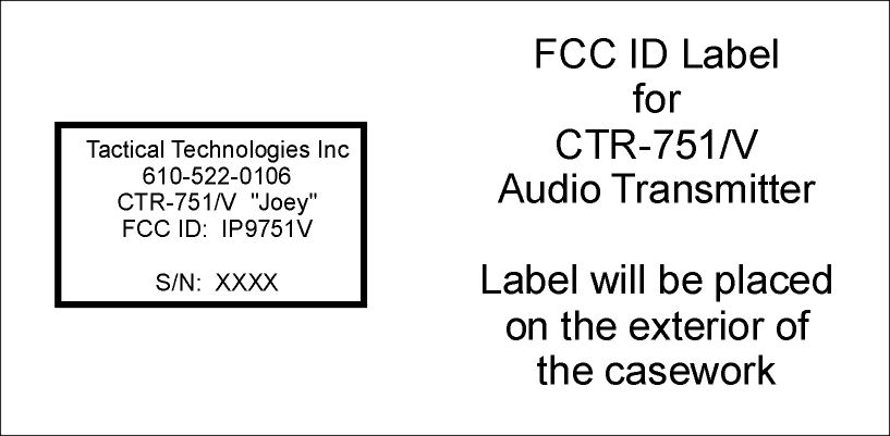
August 30, 2002 Federal Communications Commission Equipment Authorization Division RE: Request for Confidentiality, FCC ID IP9751V This letter is a request to hold the following documents pertaining to the application for FCC Type Certification for IP9751V as confidential and to withhold them from public disclosure. This request is concurrent with the FCC rules (section 0.457(d) and section 0.459) and the Freedom of Information Act (section 0.552(b)(4)). The documents are: 1.) All schematic diagrams 2.) All circuit descriptions 3.) All parts lists 4.) All circuit block diagrams Public disclosure of these pieces of design information would put Tactical Technologies Inc. at a substantial disadvantage competitively. Tactical Technologies Inc. does not make the above information available to the general public. Thank you very much for your attention to this. Sincerely, Jeffrey Olsen Engineer Tactical Technologies Inc
Test Report
Part 90 Testing CST 751/V Two Channel Synthesized FM Voice Transmitter FCC ID: IP9751V Performed by Tactical Technologies Inc. 1701 Second Ave Folsom, PA 19033 610-522-0106 August 24, 2001 The audio frequency response, low pass filter test, occupied bandwidth, frequency stability, transient behavior, and modulation testing in this application for FCC Type Certification have been performed under my direct supervision. To the best of my knowledge these tests were conducted in accordance with the procedures outlined in Part 2 and Part 90 of the Commission's Rules and Regulations. I am presently employed by Tactical Technologies Inc. in Folsom, Pennsylvania as a Design Engineer. My prior experience consists of 10 years of designing and testing communications products in the VHF portion of the spectrum. Sincerely, Jeffrey N. Olsen Engineer Tactical Technologies Inc. A. INTRODUCTION The following data are submitted in connection with this Application for Type Certification in accordance with Part 2, Subpart J, and Part 90, Subparts B,D, and I of the FCC Rules and Regulations. B. INFORM ATION REQUIRED BY PART 2 2.1003(a) See Form 731 2.1033(b) N/A 2.1003(c) (1) The full name and address of the applicant and manufacture for certification is: Tactical Technologies Inc. 1701 Second Ave. P.O. Box 91 Folsom, Pa. 19033 (2) The FCC Identifier of this device is IP9751V (3) Operating Instructions are included in the Exhibits. (4) Emission: NBFM Voice – 11K2F3 Emission Calculations are included in the Exhibits. (5) Frequency Range 150 – 174 Mhz (6) Output Power of the device is 500mw. @ 9.0 Volts (7) Maximum Power Rating is 500mw. (8) All of the Pre-amp sections run off of regulated +5.0 Volts, and the RF Final transistor runs on 9 Volts. (9) Tune up procedure are included in the Exhibits. (10) Schematics are included in the Exhibits. (11) A drawing of the equipment identification label is included in the Exhibits. (12) Photographs of the internal and external construction of the device are included in the Exhibits. (13) N/A (14) Test Data required by Part 2.1046 through 2.1057, inclusive, is measured in accordance with the procedure in Part 2.1041. (15) N/A (16) N/A (17) N/A C. SUBMISSION OF EQUIPMENT FOR TESTING - Paragraph 2.943 Upon request, the test sample will promptly be made available by Radiation Science Inc. D. DESCRIPTION OF MEASUREMENT FACILITIES - Paragraph 2.947 The open-field tests were performed on the 3 meter range maintained by Radiation Science Inc. Complete description and measurement data have been placed on file with the Commission. E. TEST DAT A This section contains results of measurements required by Parts 2 and 90 of the rules. Data are presented in tabular and/or graphical form, and measurement procedures are described within the text of each reported test. The test sample operated on 173.9125 MHz. 1. RF POWER OUTPUT - Paragraphs [2.1046(a),2.1033(c)(8),90.205(d)] Measurements pertaining to the power output of the transmitter were performed by the manufacturer. To the best of my knowledge, these tests were conducted in accordance with the procedures outlined in Parts 2 and 90 of the Commissions Rules and regulations. The data presented on Table 1 demonstrates compliance with the appropriate technical standards. 2. MODULATION CHARACTERISTICS - Paragraph [2.1047(a), 90.211(a)] Measurements pertaining to the modulation characteristics were performed by the manufacture. To the best of my knowledge, these tests were conducted in accordance with the procedures outlined in Parts 2 and 90 of the Commission's Rules and regulations. The data presented on figures 1 and 2 demonstrates compliance with the appropriate technical standards. 3. OCCUPIED BANDWIDTH - Paragraphs [2.1049, 90.211(a)] Figures 3 and 4 contain pictures taken from a Hewlett Packard 8558B Spectrum Analyzer. The transmitter was modulated with a sine wave tone at 2500 Hz at a level 16 dB above the required to produce 50% modulation at the frequency maximum response. Paragraph 90.210(d) requires that the mean power of emissions shall be attenuated below the mean output power of the transmitter by the following amounts: -- On any frequency removed from the center of the authorized bandwidth f0 to 5.625 khz removed from f0; Zero db. -- On any frequency removed from the center of the authorized bandwidth by a displacement frequency (fd in khz) of more than 5.625 khz but no more than 12.5 khz. At least (fd – 2.88khz)db. -- On any frequency removed from the center of the authorized Bandwidth by a displacement frequency (fd in khz) of no more than 12.5 khz. At least 50 + log(P) or 70db, whichever is the lesser attenuation. 4. SPURIOUS EMISSIONS AT THE 50 OHM TEST POINT ON THE TRANSMITTER [2.1053, 90.209 Emission Mask D] The transmitter was modulated per paragraph 2.1053. The spectrum was checked with the spectrum analyzer from 10 MHz to the 10th harmonic of the carrier frequency. Observed emissions not reported are attenuated more than 20 dB below the permissible value of 40 dB, i,e., 50 + log (.50W) = 47 dB given by Section 90.209. The data in Table 1 verifies that the test sample complies with Paragraph 90.209(c)(3). TABLE 1 CONDUCTED SPURIOUS EMISSIONS DATA EMISSION EMISSION FCC FREQUENCY LEVEL LIMIT (MHz) (dBc) (dBc) 173.9 REFEERENCE +27 dBm 347.8 -55 47 521.7 -58 47 695.6 -75 47 869.5 >-75 47 1043.4 >-75 47 1217.3 >-75 47 1391.2 >-75 47 1565.1 >-75 47 1739.1 >-75 47 5. FIELD STRENGTH OF SPURIOUS RADIATION - Paragraphs [2.1053,90.209] Measurements were made on the three meter range maintained by Radiation Science Inc. to quantify spurious emission level that] are radiated directly from the cabinet, control circuits, power leads and intermediate circuit elements under normal conditions of installation and operation. Particular attenuation was paid to harmonics of the carrier frequency as well as those frequencies removed from the carrier by multiples of the oscillator frequency. Data is submitted in Table 2 showing the magnitu…
Text truncated - open the document above for the full version.
Test Report
To: Stan Lyles, FCC Applications Processing Branch From: Jeff Olson, Engineer, Tactical Technologies Inc. Date: November 1, 2002 Sub: Your correspondence: REF: 24122 FCCID: IP9751V Mr Lyles: Here are the answers to the 3 questions you asked us. Thanks in advance. ---------------------Æ 1.) Thank you for correcting this for us. 2.) Rf Power Output Measurement The output power was measured with a Hewlett Packard Microwattmeter at the RF terminal of the transmitter. The electrical characteristics of the RF load were 50 ohms resistive. A 30 dB pad was inserted between the RF terminal of the transmitter and the wattmeter to avoid overloading the wattmeter. The RF power output measured .50 Watt at 9.0 Vdc. 3.) Field Strength Of Spurious Radiation 2.1053 and 90.209 Conditions: Battery Power: 9volt dc Battery Radiation into antenna - Table 2 Minimum Standard: Part 2.1053 The power of any emission shall be attenuated below the carrier power (P) by at least (50 + 10log P) dB or 70dB, whichever is the least attenuation. Calculation of Radiated Power Limit: The emissions limit is the equivalent power that would have to be fed into a dipole antenna in order to produce the same electric field strength. E = (49.2 P)1/2 / R Where: E = electric field intensity V/m P = power in watts R = distance in meters For this case E = 1.65 V/m = 124.4 dBuV/m Attenuation Requirement: Part 2.1053 requires that the spurious radiated emissions is attenuated at least (50 + 10log (.5) = 47 dB below the unmodulated carrier field strength. The limit @ 3m = 124.4 – 47dB = 77.4 dBuV/m TABLE 2 Spurious Radiated Emissions Radiation into Antenna Generator Ant. Final Horizontal Level Correction Emission FCC Limit @ 3m MHz Height dBuV Factor dB Level dBuV dBuV/m 173.9 1.50m 88.6 14.2 102.8 347.8 1.85m 25.5 18.2 43.7 77.4 521.7 1.30m 24.1 21.3 45.4 77.4 695.6 1.75m 23.4 24.7 48.1 77.4 869.5 No emissions were observed 77.4 1217 No emissions were observed 77.4 1391 No emissions were observed 77.4 1565 1.00m * 77.4 1739 1.00m * 77.4 Generator Ant. Final Vertical Level Correction Emission FCC Limit @3m MHz Height dBuV Factor dB Level dBuV dBuV/m 173.9 2.20m 98.5 15.5 114.0 347.8 2.15m 46.5 17.5 64.0 77.4 521.7 2.15m 35.2 21.5 56.7 77.4 695.6 2.45m * 77.4 869.5 No emissions were observed 77.4 1043 1.00m * 77.4 1217 No emissions were observed 77.4 1391 1.00m * 77.4 1565 1.00m * 77.4 1739 1.00m * 77.4 * Spurious Emissions that were not reported were more than 30 dB below the permitted limit. Test Result: The strongest spurious emission was the second harmonic of 173.9 MHz test frequency with a level of 64 dBuV/m @ 3m. This is 13.4 dB below the limit, and 50 dBc. Radiated Spurious Emissions: TIA/EIA-603-A-2001 2.2.12 The radiated spurious emissions was measured from the transmitter transmitting into a antenna which was placed on a table 3 meters away from the test antenna. Each spurious frequency that was recorded was taken by raising the test antenna from 1 to 4 meters until the maximum reading was obtained. The transmitter was then replaced with a substitution antenna, which was fed from a Rf Signal Generator. The output power of the generator was adjusted to match the transmitters radiated emission at that frequency and antenna height.
Test Report
Substitution Method: Electromagnetic Emission Test FCCID: IP9751V Test Code RE Date: 11/21/02 RSI Equipment Numbers: 31, 52, 80, 84, 91 196, 391 Technician E U T Manufacturer: Tactical Technologies Model#: CST 751 Serial # 220 Mode: Transmit into dummy load Frequency Range: 300MHz to 1.8GHz Engineer Temperature: 54°F Humidity: 36% Additional Info: Intentional Radiator Test Spec: FCC Radiated Distance: 3 meter Antenna: Bicon, L/P, W/G HORIZ. BB NB VERT. H E Conducted Line: Function: BB NB Correction Factors FREQ. IND, LEVEL ANT. Cable Loss Final Level Antenna Height Azimuth Remarks Hz dBm dBi dB dBm Meters degrees (subs.) (gain) Horizontal 347.82M -61.6 5.9 -4.0 -59.7 1.4 270 521.74M -48.5 5.6 -5.6 -48.5 1.0 180 695.65M -51 6.2 -6.2 -51 1.0 180 869.56M -56 6.3 -7.5 -57.2 1.0 0 1.043G -61 6.8 -6.7 -60.9 1.0 0 1.217G -40 7.7 -8.2 -60.5 1.0 0 1.391G -43 8.8 -9.0 -67.2 1.0 0 1.565G -33 9.1 -9.5 -67.4 1.1 0 1.739G -31 9.0 -9.0 -63.0 1.2 0 Vertical 347.82M -61 6.4 -4.0 -58.6 1.7 315 521.74M -49 6.1 -5.6 -48.5 1.2 315 695.65M -47 6.0 -6.2 -47.2 1.0 315 869.56M -52 6.8 -7.5 -52.7 1.3 270 1.043G -85 7.1 -6.7 -84.6 1.0 0 1.217G ns 7.8 -8.2 - 1.0 0 1.391G -76.5 8.5 -9.0 -77 1.0 0 1.565G -68.5 9.4 -9.5 -68.4 1.1 0 1.739G -74 9.4 -9.0 -73.6 1.1 0 Note: ns=no signal detected Maximum level @ 3 meters 77.4 dBuV or -29.6 dBm X X X Test Range at Radiation Sciences for Substitution Method - EUT @ < 1 gig Test Range at Radiation Sciences – Substitution Method EUT @ > 1 gig
Test Report
OUTPUT POWER INTO 50 OHMS @ 9VOLTS 0 50 100150200250300350400450500 150MHz 154MHz 158MHz 162MHz 166MHz 170MHz 174MHz mW IP9751V
Contact Information
Applicant
Richard B Snyder(President)
Test Firm
Radiation Sciences IncorporatedDaniel Signore
215-256-4133Fax: 215-256-0775
Technical Specifications
| # | Rule Parts | Frequency Range | Power Output | Emission | Tolerance |
|---|---|---|---|---|---|
| 1 | 90.355 | 150 MHz - 174 MHz | 500.00 mW | 11K0F3E | 2.5000000000 ppm |
Other Applications from Tactical Technologies Inc
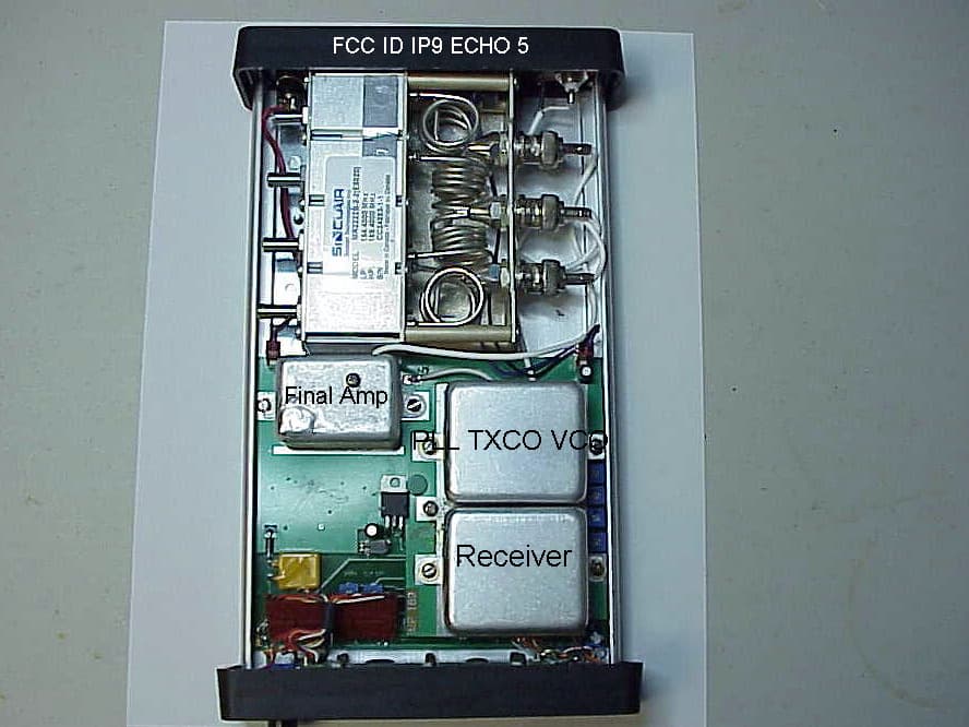
IP9ECHO5
Aug 21, 2005Repeater
Equipment Class
TNB - Licensed Non-Broadcast Station Transmitter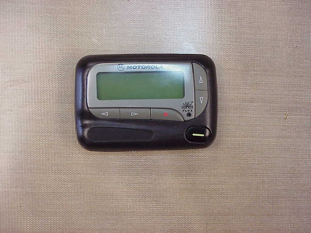
IP9801VI
Jun 22, 2005Synthesized VHF Surveillance Voice Transmitter
Equipment Class
TNT - Licensed Non-Broadcast Transmitter Worn on Body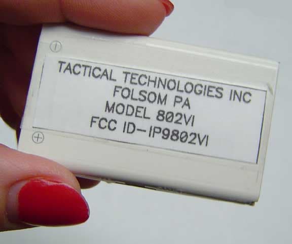
IP9802VI
May 05, 2005Synthesized VHF Surveillance Voice Transmitter
Equipment Class
TNT - Licensed Non-Broadcast Transmitter Worn on Body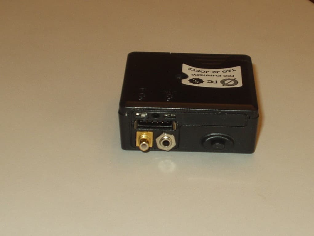
IP975XVI
Mar 28, 2005Synthesized VHF Surveillance Voice Transmitter
Equipment Class
TNT - Licensed Non-Broadcast Transmitter Worn on Body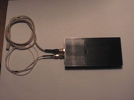
IP9620V
Apr 07, 2002Law Enforcement Surveillance Voice Transmitter
Equipment Class
LMS - Part 90 Location & Monitoring Transmitter