IP9801VISynthesized VHF Surveillance Voice Transmitter
Tactical Technologies Inc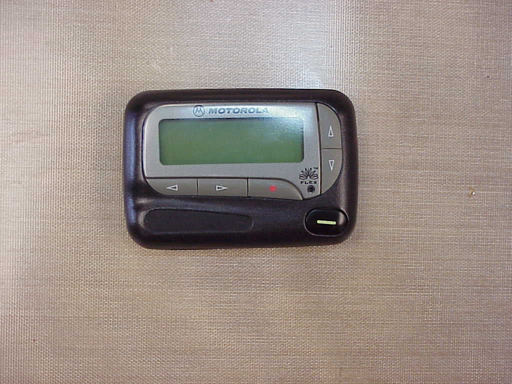
Click to zoom
Application Details
- Equipment Class
- TNT - Licensed Non-Broadcast Transmitter Worn on Body
- Date of Grant
- Jun 22, 2005
- Application Purpose
- Original Equipment
- Date of Application
- Jun 22, 2005
- Equipment Note
- Synthesized VHF Surveillance Voice Transmitter
- Frequency Range
- 150.00000000 - 174.00000000
- Company
- Tactical Technologies Inc
- Country
- United States
Documents & Files

Document Text
Text extracted from the exhibit documents filed with the FCC. Open a document above to read the original.
Users Manual
Synthesized VHF Surveillance Voice Transmitter Pager Transmitter CST801VI CST801VI – User Guide, 1.0.3 Copyright & Information Copyright & Information © Copyright 2003 - 2005 TTI - All rights reserved. No part of this publication or associated software may be copied without the written permission of TTI. You may not modify, adapt, translate, reverse engineer, disassemble or create derivative works based on the hardware, firmware, software or documentation. Condition of Use The user undertakes that, • They are a bona fide law enforcement agency with technical capabilities. • The CST801VI is being used to fulfill official requirements. • The CST801VI will be used with discretion. • Precautions will be undertaken to keep details restricted to members of their organization requiring such information. The user acknowledges that, • The CST801VI is for use by law enforcement agencies. • The CST801VI may not comply with government type approval. • The users will be responsible for satisfying themselves that the 801 may be legally operated in the district where the user intends to deploy it. Disclaimer Care has been taken in assuring the quality of the CST801VI but the developers, TTI and any associated company, distributor or reseller do not accept responsibility for errors. In no event shall the aforementioned parties be liable for any loss of profit or any other commercial damage including, but not limited to, special, incidental, consequential or other damages arising from the provision of the CST801VI or associated software or peripherals to the user. © TTI Law Enforcement ONLY © TTI Law Enforcement ONLY CERTIFICATION STANDARDS FCC Notice This device complies with Part 90 of the FCC Rules. FCCID: IP9801VI This device meets FCC requirements as a controlled/occupational environmental device closer than 2.5 cm. Operations is subject to the following two conditions: 1. this device may not cause harmful interference, and 2. this device must accept any interference received, including interference that may cause undesired operation Australia / New Zealand Pending Industry Canada Pending European Union Pending © TTI Law Enforcement ONLY CST801VI – User Guide, 1.0.3 Introduction © TTI Law Enforcement ONLY INTRODUCTION Tactical Technologies Inc. (Model number CST801VI), is a 1 channel, .25 watt VHF FM synthesized voice transmitter for law enforcement use. The operating frequency is only a 4 Mhz section from 150 – 174 Mhz due to the narrow band antenna. The unit utilizes an internal antenna and a single internal microphone for transmitter operations. The CST801VI can be equipped with an optional scrambler for added transmitter security. Figure 1, The CST801VI Transmitter © TTI Law Enforcement ONLY CST801VI – User Guide, 1.0.3 Introduction © TTI Law Enforcement ONLY Operating Frequencies The frequencies available on the CST801VI are spaced in 12.5 kHz steps beginning with 150.0000 MHz and ending with 174.0000 MHz. Simply put, “12.5 kHz steps” means your frequency must be in any of the following configurations: xxx . x000 xxx . x125 xxx . x250 xxx . x375 xxx . x500 xxx . x625 xxx . x750 xxx . x875 This gives the CST801VI the ability to transmit on any one of 280 available frequencies. Any other frequency selection will result in an error message. Citation Receivers Any of Tactical Technologies Inc. Citation Receiver/Recorder kits (Series 20 and higher) are able to program frequency, power, and scrambling settings into the CST801VI. A special Citation Interface Cable, is supplied with the CST801VI for such an application. See your TTI representative for more information. If you already own a Citation 20 or higher receiver, programming instructions are found in the Citation Operators Manual. © TTI Law Enforcement ONLY CST801VI – User Guide, 1.0.3 Introduction © TTI Law Enforcement ONLY Range of the CST802VI Transmitter It is impossible to state absolutes about how far an RF transmitter like the CST801VI will transmit. Many variables affect the range of a device including buildings, trees, weather, construction materials, installation, etc. All things being perfect (meaning transmissions are outdoors over flat terrain with no obstructions), a .25 watt CST801VI should be able to easily transmit over a ¼ mile. You should expect less distance than that however, in a real world operation. One of the most important variables, and one that the operator can actually control, is the placement of the receiver and the receiving antenna. A good rule to follow is the higher the antenna placement, the better chance you have of quality reception. This alone will increase your operating range. Just having the CST801VI in an ideal location is not enough. © TTI Law Enforcement ONLY
Cover Letter(s)
Federal Communications Commission Equipment Authorization Division RE: Request for Confidentiality, FCC ID IP9801VI This letter is a request to hold the following documents pertaining to the application for FCC Type Certification for IP9801VI as confidential and to withhold them from public disclosure. This request is concurrent with the FCC rules (section 0.457(d) and section 0.459) and the Freedom of Information Act (section 0.552(b)(4)). The documents are: 1.) All schematic diagrams 2.) All circuit descriptions Public disclosure of these pieces of design information would put Tactical Technologies Inc. at a substantial disadvantage competitively. Thank you very much for your attention to this. Sincerely, Jeffrey Olsen Engineer Tactical Technologies Inc
Cover Letter(s)
American Telecommunications Certification Body Inc. 6731 Whittier Ave, McLean, VA 22101 June 9, 2005 RE: FCC ID: IP9801VI_ATCB002493 Attention: Jeff Olson I have a few comments on this Application. Please note that further comments may arise in response to answers provided to the questions below. 1. Please provide the external photos of the device. 2. Please provide internal photos that show the control and placement of the boards in the device. 3. The measured device power is approximately 230mW. The level at which SAR becomes relevant is about 330mW for this device. If the device operates at a 50% duty cycle this means that SAR may become an issue if the ERP is greater than 660mW. If the gain of the antenna is more than 4dB this would put the ERP power over this level and SAR may be required. Please provide antenna gain information on this device so a determination relevant to SAR can be made. 4. Please note that as this is a portable device worn on the body the power listed on the grant needs to be ERP. The report provided conducted antenna terminal power and not ERP. Please note that this must be a measured ERP. Consequently the values for 170MHz shown in the table on page 9 of the report cannot be used for ERP. Please provide the measured ERP of the device using the antenna substitution method described in TIA 603. 5. Please note that the equation dBfund – (50+10logP) should always come to -20dBm in the same fashion that dBfund – (43+10logP) would always be -13dBm. This means that the reverse field strength on a radiated emission would have to be less than 87dBuV/m not 82.8dBuV/m. Please also note that a 250mW device would have a conversion to field strength of 121.4dBuV/m and not 125dBuV/m. The actual power level (230mW) would have a field strength of 121dBuV/m. 125dBuV/m would be a conducted power of almost 600mW. The resulting dBc for 250mW would be 23.97 – (50 + 10log(.25)) or 23.97 – (50 + -6.03). This then equates to -20dBm or 87dBuV/m or 43.97dBc. The device is still compliant but the report should give reference to the proper limits. Please also note that the reason TIA603 requires measured ERP values is to eliminate or reduce the site factors involving cable, antenna factors and other variable site losses. 6. Dennis Ward mailto:[email protected] The items indicated above must be submitted before processing can continue on the above referenced application. Failure to provide the requested information may result in application termination. Correspondence should be considered part of the permanent submission and may be viewed from the Internet after a Grant of Equipment Authorization is issued. Please do not respond to this correspondence using the email reply button. In order for your response to be processed expeditiously, you must submit your documents through the AmericanTCB.com website. Also, please note that partial responses increase processing time and should not be submitted. Any questions about the content of this correspondence should be directed to the sender.
External Photos
External photos
Internal Photos
Internal Photos
Operational Description
Circuit Description of the CST801VI Transmitter The CST801VI is broken down into 4 sections. Audio - audio amplifier, pre-emphasis, audio deviation adjustment, and agc limiting. Txco/Pll - phase lock loop, loop filter, Reference Oscillator, VCO, and VCO Buffer OOL - out of lock detection, pre-amplifier, and RF final amplifier. DC - DC - dc to dc converter Audio Section: The transmitter audio is amplified by U7A, the resistors (R45 and R48) and capacitors (C55 and C56) create the 6 Dbm/Octive pre-emphasis curve from 300 – 3000 Hz. The out put of the Op Amp U7 is ac coupled to a diode rectifier (D1) this voltage is filtered by C52 which drives the audio limiting FET (Q5). The drain to source impedance shorts some of the audio to ground to prevent over modulation. (R35) adjusts the amount of transmitted audio deviation. Txco/Pll Section: The 12.8 Mhz reference Oscillator (Y2) provides the 5 ppm Transmitter Temperature Stability over the range of -30 to +60 degree C. The TX frequency adjustment is controlled by (R11). The Phase Lock Loop (U6) contains 3 programmable counters which are loaded by a serial data stream from the microprocessor (U3). The frequency is loaded into the B and A counters and the step size is loaded into the R counter. The Voltage controlled oscillator (Q6) is connected to a VCO/Buffer (U2), the 2 outputs from the buffer connect to the pre-amplifier and the other is applied to the phase detector of the PLL (U6). The output of the phase detector pin 2 of (U6) is filtered into a dc voltage by the loop filter (C46,C47,R34,R16). This voltage is applied to the VCO varactor (D2) which changes capacitance with voltage moving the VCO frequency. Out of Lock RF amplifier Section: When the VCO frequency is locked to the programmed transmitter frequency a logic level high from pin 14 of the PLL (U6) is applied to the N channel FET (Q3) which turns on the P channel FET (Q1) applying a dc bias voltage to the pre-amplifier (Q4) and the RF final Amplifier (Q2). The output from the VCO/Buffer (U2) is amplified by the pre-amp (Q4), its output level is +10 dBm. The collector of (Q4) is loaded into the final amplifier by the LC network of (C3,C58,L1). (Q2) the RF final amplifier has ~ 13 dBm of gain from 150 – 174 Mhz. The drain of the final amplifier is match into 50 ohms through the LC network of (L8,C38,C39) an additional low pass filter (C40,L9,C70) is added to provide more harmonic attenuation. DC – DC Converter : U1 on the dc – dc pcb converters the pager 1.5 volts to 3.0 volts through the switching mode converter. The 3.0 volts is applied to the TX pcb and is regulated down to 2.85 volts to supply all the digital components on the transmitter. The 3.0 volts from the dc-dc converter is only applied to the RF Final transistor (Q2).
Test Report
Part 2 & 90 Testing Synthesized FM Voice Transmitter Model CST801VI FCC ID: IP9801VI Tactical Technologies Inc. 1701 Second Ave Folsom, PA 19033 610-522-0106 A. INTRODUCTION The following data are submitted in connection with this Application for Type Certification in accordance with Part 2, Subpart J, and Part 90, Subparts B,D, and I of the FCC Rules and Regulations. B. INFORMATION REQUIRED BY PART 2 2.1003(a) See Form 731 2.1033(b) N/A 2.1003(c) (1) The full name and address of the applicant and manufacture for certification is: Tactical Technologies Inc. 1701 Second Ave. P.O. Box 91 Folsom, Pa. 19033 (2) The FCC Identifier of this device is IP9801VI (3) Operating Instructions are included in the Exhibits. (4) Emission: NBFM Voice – 11K2F3E Emission Calculations are included in the Exhibits. (5) Frequency Range 150 – 174 Mhz (6) Output Power of the device is 250mw. @ 1.5 Volts (7) Maximum Power Rating is 250mw. (8) All of the Pre-amp sections run off of 2.85v, and RF Final transistor run off of regulated +3.00 Volts. (9) Tune up procedure is included in the Exhibits. (10) Test Data required by Part 2.1046 through 2.1057, inclusive, is measured in accordance with the procedure in Part 2.1041. C. SUBMISSION OF EQUIPMENT FOR TESTING - Paragraph 2.943 Upon request, the test sample will promptly be made available by Tactical Technologies Inc. D. DESCRIPTION OF MEASUREMENT FACILITIES - Paragraph 2.947 The open-field tests were performed on the 3 meter range maintained by Radiation Science Inc. Complete description and measurement data have been placed on file with the Commission. E. TEST DATA This section contains results of measurements required by Parts 2 and 90 of the rules. Data is presented in tabular and/or graphical form, and measurement procedures are described within the text of each reported test. 1. RF POWER OUTPUT - Paragraphs [2.1046(a),2.1033(c)(8),90.205(d)] Power output measurements were made at the RF connector. This test was done with an unmodulated carrier in accordance with part 90.205(d) The power output was measured with a Spectrum Analyzer with a series 30 dBm pad. The electrical characteristics of the RF load was 50 ohms 0j. The RF power output was measured from 170 Mhz – 174 Mhz The RF output power did not vary with changes in the supply voltage, due to the system regulation. OUTPUT POWER INTO 50 OHMS @ 1.5 VOLTS 0 20 40 60 80 100 120 140 160 180 200 220 240 260 170.0MHz170.5Mhz171.0Mhz171.5MHz172.0MHz172.5MHz173.0MHz173.5MHz174.0MHz mW IP9801VI 2. MODULATION CHARACTERISTICS - Paragraph [2.1047(a), TIA/EIA -603 3.2.6] Measurement data showing the frequency response of the transmitter is shown in the graph below. The blue line is the 6 dBm / Octive, and the pink line is the modulation limiting. A signal generator was connected to the transmitters mic input, and the audio output was measured from a communication receivers demod output. The pink lines input was 20 dBm greater then the blue lines input. INPUT SIGNAL VS. DEVIATION FCC ID # IP9801VI 0.0% 10.0% 20.0% 30.0% 40.0% 50.0% 60.0% 70.0% 80.0% 90.0% 100.0% 300Hz500Hz750Hz1000Hz1500Hz2000Hz2500Hz3000Hz6000Hz12000Hz24000Hz DEVIATION = 2.5kHZ @ 100% 3. OCCUPIED BANDWIDTH - Paragraphs [2.1049, 90.210] Figures 3 and 4 contain pictures taken from a Spectrum Analyzer. The transmitter was modulated with a sine wave tone at 2500 Hz at a level 16 dB above the required to produce 50% modulation at the frequency maximum response. Paragraph 90.210(d) requires that the mean power of emissions shall be attenuated below the mean output power of the transmitter by the following amounts: -- On any frequency removed from the center of the authorized bandwidth f0 to 5.625 khz removed from f0; Zero db. -- On any frequency removed from the center of the authorized bandwidth by a displacement frequency (fd in khz) of more than 5.625 khz but no more than 12.5 khz. At least (fd – 2.88khz)db. -- On any frequency removed from the center of the authorized Bandwidth by a displacement frequency (fd in khz) of no more than 12.5 khz. At least 50 + log(P) or 70db, whichever is the lesser attenuation. Part 90.210 Emission Mask D Part 90.210 Emission Mask D 4. SPURIOUS EMISSIONS AT THE 50 OHM TEST POINT ON THE TRANSMITTER [2.1053, 90.210 Emission Mask D] The transmitter was modulated per paragraph 2.1053. The spectrum was checked with the spectrum analyzer from 10 MHz to the 10th harmonic of the carrier frequency. Observed emissions not reported are attenuated more than 20 dB below the permissible value of 40 dB, i,e., 50 +10log (.25W) = 44 dB given by Section 90.210. The data in Table 1 verifies that the test sample complies with Paragraph 5. FIELD STRENGTH OF SPURIOUS RADIATION - Paragraphs [2.1053, 90.210] Measurements were made on the three meter range maintained by Radiation Science Inc. to quantify spurious emission level that] are radiated directly from the cabinet, control circuits, power leads and intermediate circuit elements under normal conditions of installation and operation. Particular attenuation was paid to harmonics of the carrier frequency as well as those frequencies removed from the carrier by multiples of the oscillator frequency. Data is submitted in Table 2 showing the magnitude of harmonics and other spurious emissions from 30 MHz through the 10th harmonic. The test sample with its internal antenna was placed on a non- conductive table one meter above the ground plane in order to determine the maximum level at each emission. Both horizontal and vertical site antenna polarization were employed. The antenna was raised 1 to 4 meters in height and the equipment under test was rotated 360 degrees to minimize the emission. The reference level for spurious radiation was taken as an ideal dipole excited by the measured output power according to the following relationship: E = (49.2 P)1/2 / R Where: E = electric-field intensity in Volts/meter P = transmitted power in Watts .230W or 23.62dBm R = distance in meters For this case: E = 1…
Text truncated - open the document above for the full version.
Contact Information
Applicant
Richard B Snyder(President)
Technical Contact
Tactical Technologies IncJeff Olson
1701 Second Ave · Folsom, Pennsylvania · United States
Technical Specifications
| # | Rule Parts | Frequency Range | Power Output | Emission | Tolerance |
|---|---|---|---|---|---|
| 1 | 90 | 150 MHz - 174 MHz | 230.00 mW | 11K0F3E | 2.5000000000 ppm |
Other Applications from Tactical Technologies Inc
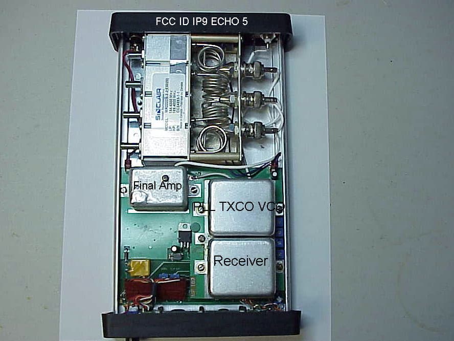
IP9ECHO5
Aug 21, 2005Repeater
Equipment Class
TNB - Licensed Non-Broadcast Station Transmitter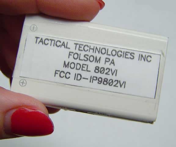
IP9802VI
May 05, 2005Synthesized VHF Surveillance Voice Transmitter
Equipment Class
TNT - Licensed Non-Broadcast Transmitter Worn on Body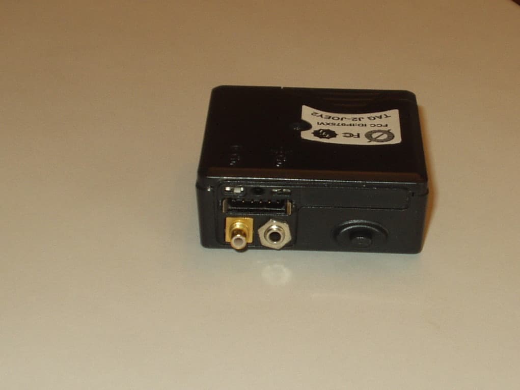
IP975XVI
Mar 28, 2005Synthesized VHF Surveillance Voice Transmitter
Equipment Class
TNT - Licensed Non-Broadcast Transmitter Worn on Body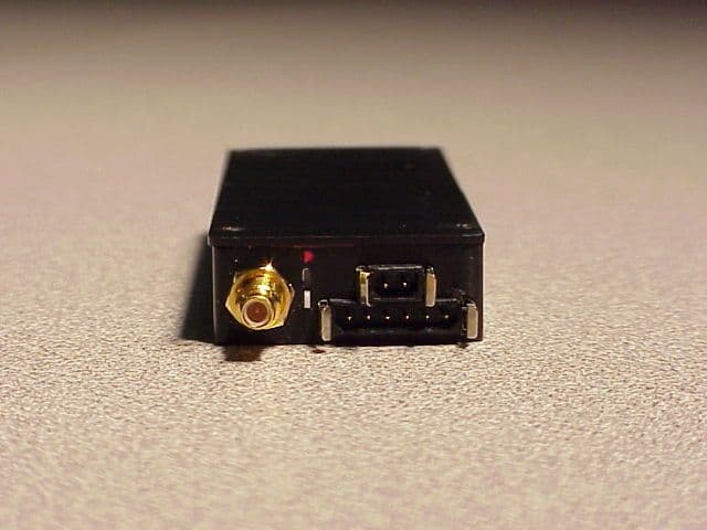
IP9751V
Dec 01, 2002Law Enforcement Surveillance Transmitter
Equipment Class
LMS - Part 90 Location & Monitoring Transmitter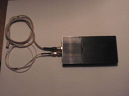
IP9620V
Apr 07, 2002Law Enforcement Surveillance Voice Transmitter
Equipment Class
LMS - Part 90 Location & Monitoring Transmitter