IPH-0046400Aviation Transponder
Garmin International Inc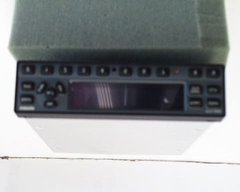
Click to zoom
Application Details
- Equipment Class
- TNB - Licensed Non-Broadcast Station Transmitter
- Date of Grant
- Jun 24, 2002
- Application Purpose
- Original Equipment
- Date of Application
- Jun 24, 2002
- Equipment Note
- Aviation Transponder
- Frequency Range
- 1090.00000000 - 1090.00000000
- Company
- Garmin International Inc
- Country
- United States
Documents & Files
Document Text
Text extracted from the exhibit documents filed with the FCC. Open a document above to read the original.
Users Manual
â ââ â GARMIN International, Inc. 1200 E. 151 st Street Olathe, KS 66062 USA 190-00207-02 Revision 1 March 2002 GTX TM 330, GTX TM 330D TRANSPONDER INSTALLATION MANUAL Page AGTX 330 Installation Manual Rev. 1190-00207-02 © Copyright 2002 GARMIN Ltd. or its subsidiaries All Rights Reserved Except as expressly provided herein, no part of this manual may be reproduced, copied, transmitted, disseminated, downloaded or stored in any storage medium, for any purpose without the express prior written consent of GARMIN. GARMIN hereby grants permission to download a single copy of this manual and of any revision to this manual onto a hard drive or other electronic storage medium to be viewed and to print one copy of this manual or of any revision hereto, provided that such electronic or printed copy of this manual or revision must contain the complete text of this copyright notice and provided further that any unauthorized commercial distribution of this manual or any revision hereto is strictly prohibited. Information in this document is subject to change without notice. GARMIN reserves the right to change or improve its products and to make changes in the content without obligation to notify any person or organization of such changes or improvements. GARMIN International, Inc. 1200 E. 151 st Street Olathe, KS 66062 USA Telephone: 913-397-8200 Dealer Line: 1-800-800-1420 Web Site Address: www.garmin.com INFORMATION SUBJECT TO EXPORT CONTROL LAWS This document may contain information which is subject to the Export Administration Regulations (ìEARî) issued by the United States Department of Commerce (15 CFR, Chapter VII, Subchapter C) and which may not be exported, released, or disclosed to foreign nationals inside or outside of the United States without first obtaining an export license. A violation of the EAR may be subject to a penalty of up to 10 years imprisonment and a fine of up to US$1,000,000 under Section 2410 of the Export Administration Act of 1979. Include this notice with any reproduced portion of this document. RECORD OF REVISIONS RevisionRevision Date DescriptionECO # 1 03/22/00Preliminary Release- GTX 330 Installation ManualPage i 190-00207-02Rev 1 TABLE OF CONTENTS To be supplied Page iiGTX 330 Installation Manual Rev 1190-00207-02 This page intentionally left blank GTX 330 Installation ManualPage 1-1 190-00207-02Rev. 1 1.GENERAL DESCRIPTION 1.1INTRODUCTION This manual describes the physical, mechanical, and electrical characteristics and the installation requirements for the GTX 330 Mode S Transponder and GTX 330D Diversity Mode S Transponder. In this manual, the term GTX 330 applies to both transponders unless otherwise stated. Information pertaining to the maintenance, alignment, and procurement of replacement parts is found in the GTX 330 Maintenance Manual, P/N 190-00207-05. After installation of the GTX 330, FAA Form 337 must be completed by an appropriately certificated agency to return the aircraft to service. 1.2EQUIPMENT DESCRIPTION The Garmin GTX 330 is a panel mounted Mode S Transponder with the addition of timers, altitude reporting, mode S interrogation and reply, and multiple transmit/receive ARINC 429 and RS232 data ports. The Mode S transponder has the capability to transmit a unique address for every aircraft. The GTX 330 is a radio transmitter and receiver that operates on radar frequencies, receiving ground radar or TCAS interrogations at 1030 MHz and transmitting a coded response of pulses to ground-based radar on a frequency of 1090 MHz. The GTX 330 is equipped with IDENT capability that activates the Special Position Identification (SPI) pulse for 18 seconds. As with other Mode A/Mode C transponders, the GTX 330 replies with any one of 4,096 codes, which differ in the position and number of pulses transmitted. By replying to ground transmissions or TCAS interrogations, the GTX 330 enables ATC to display aircraft identification, altitude and ground speed as well as identification numbers on ATC radar screens or TCAS traffic indicators. The GTX 330 is configured with all key controls. The layout of the front panel keys and displays segregates the transponderís primary functions from the secondary functions. The unit can be configured so the aircraft avionics master bus can turn the unit on. 1.3INTERFACE SUMMARY The GTX 330 provides the following interface connections via the rear connector: • Ten (10) encoding altimeter inputs. • External IDENT input. • External STBY input. • External suppression pulse input. • Switched power output of up to 1.5 amps (for digital altitude encoder power). • Aircraft power input (11 to 33 volts). • Aircraft dimming buss input voltage. • Aircraft master switch turn-on option. Page 1-2GTX 330 Installation Manual Rev. 1190-00207-02 • Serial altitude or GPS groundspeed input. • Serial altitude output. • Mode S with Extended Squitter, Comm A and Comm B protocol. • Temperature, Altitude Hold, Density Altitude and the ability to enter flight ID or tail numbers. • Digitally recorded voice and discrete warning annunciator activated by Altitude Hold when limits are exceeded. • Diversity: GTX 330 is available with or without the Diversity feature. 1.4GTX 330 TECHNICAL SPECIFICATIONS 1.4.1 GTX 330 Electrical Specifications SPECIFICATIONCHARACTERISTIC TSO, JTSO; GTX 330 TSO-C112 CL 2A4 121 010 , JTSO-2C112a. TSO, JTSO; GTX 330D TSO-C112 CL 2A4 121 011 , JTSO-2C112a. TSO ENV CAT Refer to appendix A Applicable Documents RTCA DO-160D, DO-181C Temperature Range -45°C to +55°C (Continuous Operation) Power Requirements 11.0 to 33.0 Vdc; Power Input: 22 Watts typical, 45 Watts Maximum Humidity 95% @ +55°C for 16 Hours; 85% @ +38°C for 32 Hours Altitude 55,000 Feet Transmitter Frequency 1090 MHz Transmitter Power 125 Watts minimum, 250 Watts nominal. Receiver Frequency 1030 MHz Receiver Sensitivity -74 dBm Nominal for 90% replies Mode A Capability 4096 Identification Codes Mode C Capability 100 Foot Increments from -1000 to 62,700 feet. 25 Foot Incr…
Text truncated - open the document above for the full version.
External Photos
ROGERS LABS, INC. GARMIN INTERNATIONAL, INC. 4405 W. 259th Terrace MODEL: GTX 330D, 011-00455-( ) Louisburg, KS 66053 Test #: 020326 FCC ID: IPH-0046400 Phone/Fax: (913) 837-3214 Test to: FCC Parts 2 and 87 Page 1 of 1 GTX330DExtPho.doc 4/9/2002 External Photos of for GTX 330D
ID Label/Location Info
ROGERS LABS, INC. GARMIN INTERNATIONAL, INC. 4405 W. 259th Terrace MODEL: GTX 330D, 011-00455-( ) Louisburg, KS 66053 Test #: 020326 FCC ID: IPH-0046400 Phone/Fax: (913) 837-3214 Test to: FCC Parts 2 and 87 Page 1 of 1 GTX330DIdLbl.doc 4/9/2002 FCC ID Label Location and information for GTX 330D Artwork for GTX 330D ( note the line through the ID number will be removed for production labels).
Internal Photos
ROGERS LABS, INC. GARMIN INTERNATIONAL, INC. 4405 W. 259th Terrace MODEL: GTX 330D, 011-00455-( ) Louisburg, KS 66053 Test #: 020326 FCC ID: IPH-0046400 Phone/Fax: (913) 837-3214 Test to: FCC Parts 2 and 87 Page 1 of 5 GTX330DTsup.doc 4/9/2002 Internal Photographs for GTX 330D ROGERS LABS, INC. GARMIN INTERNATIONAL, INC. 4405 W. 259th Terrace MODEL: GTX 330D, 011-00455-( ) Louisburg, KS 66053 Test #: 020326 FCC ID: IPH-0046400 Phone/Fax: (913) 837-3214 Test to: FCC Parts 2 and 87 Page 2 of 5 GTX330DTsup.doc 4/9/2002 ROGERS LABS, INC. GARMIN INTERNATIONAL, INC. 4405 W. 259th Terrace MODEL: GTX 330D, 011-00455-( ) Louisburg, KS 66053 Test #: 020326 FCC ID: IPH-0046400 Phone/Fax: (913) 837-3214 Test to: FCC Parts 2 and 87 Page 3 of 5 GTX330DTsup.doc 4/9/2002 ROGERS LABS, INC. GARMIN INTERNATIONAL, INC. 4405 W. 259th Terrace MODEL: GTX 330D, 011-00455-( ) Louisburg, KS 66053 Test #: 020326 FCC ID: IPH-0046400 Phone/Fax: (913) 837-3214 Test to: FCC Parts 2 and 87 Page 4 of 5 GTX330DTsup.doc 4/9/2002 ROGERS LABS, INC. GARMIN INTERNATIONAL, INC. 4405 W. 259th Terrace MODEL: GTX 330D, 011-00455-( ) Louisburg, KS 66053 Test #: 020326 FCC ID: IPH-0046400 Phone/Fax: (913) 837-3214 Test to: FCC Parts 2 and 87 Page 5 of 5 GTX330DTsup.doc 4/9/2002
Parts List/Tune Up Info
ROGERS LABS, INC. Garmin International, Inc. 4405 W. 259th Terrace MODEL: GTX330D Louisburg, KS 66053 Test #: 020326 FCC ID#: IPH-0046400 Phone/Fax: (913) 837-3214 Test to: FCC Parts 2 and 87 Page 1 of 1 GTX330DTune.doc 04/09/2002 Alignment procedures for GTX330D. 1. TX Alignment Procedure Alignment of the GTX330 TX board consists of adjusting five trimmer capacitors for best power consistent with acceptable rise time and fall time. 1.1. Initial Trimmer Cap Settings Before applying power to the unit, preset the trimmer as described below: C124: Turn fully clockwise, then turn counterclockwise 5 turns. C127: Turn fully clockwise, then turn counterclockwise 3 turns. C129: Turn fully clockwise, then turn counterclockwise 4 turns. C131: Turn fully clockwise, then turn counterclockwise 1 turns. C135: Turn fully clockwise, then turn counterclockwise 5 turns. 1.2. TX Alignment Steps 1. Turn on the unit in test mode. 2. Set the SDX2000 or IFR1400 to ATCRBS mode, 50 PRF and interrogate the unit. 3. Adjust C135 for maximum power. The measured power should be greater than 150 watts. 4. Adjust C131 clockwise until pulse power just begins to drop, then turn counterclockwise ½ turn. 5. Adjust C129 for maximum power consistent with minimum rise time. 6. Repeat steps 3, 4, and 5. 7. Adjust the multiturn pot R177 for minimum pulse width. 8. Via the front panel display, select the test page for setting pulse width. 9. Using the CRSR button, select the pulse width field. 10. Set the pulse width to the first setting which gives a pulse width at or below 450 nS. Press the 8 key to decrease pulse width and the 9 key to increase the pulse width. The CRSR button must be pressed to load the new value. 11. Adjust the multiturn pot R177 to increase pulse width and fall time. The desired pulse width is 470 +/- 5 nS. The corresponding fall time should be in the range 80-110 nS. 12. Verify that pulse rise time is less than 85 nS, fall time is greater than 80 nS, and power >160 watts at the end of a 1.5 dB cable.
Test Report
TEST REPORT For APPLICATION of CERTIFICATION For GARMIN INTERNATIONAL, INC. 1200 East 151st Street Olathe, KS 66062 Phone: (913) 397-8200 MODEL: GTX 330D, 011-00455-( ) FREQUENCY: 1090 MHz FCC ID: IPH-0046400 Test Date: March 26, 2002 Certifying Engineer: Scot D. Rogers ROGERS LABS, INC. 4405 W. 259th Terrace Louisburg, KS 66053 Phone: (913) 837-3214 FAX: (913) 837-3214 This report shall not be reproduced except in full, without the written approval of the laboratory. This report must not be used by the client to claim product endorsement by NVLAP or any agency of the U.S. Government. ROGERS LABS, INC. 4405 West 259 th Terrace Louisburg, KS 66053 Phone / Fax (913) 837-3214 NVLAP Accredited Laboratory NVLAP Lab Code: 200087-0 ROGERS LABS, INC. GARMIN INTERNATIONAL, INC. 4405 W. 259th Terrace MODEL: GTX 330D, 011-00455-( ) Louisburg, KS 66053 Test #: 020326 FCC ID: IPH-0046400 Phone/Fax: (913) 837-3214 Test to: FCC Parts 2 & 87 Page 2 of 23 GTX330DTstRpt 5/21/2002 TABLE OF CONTENTS FORWARD: 3 LIST OF TEST EQUIPMENT 3 EQUIPMENT TESTED 4 EQUIPMENT AND CABLE CONFIGURATION 4 Test Setup 4 2.1033(C) APPLICATION FOR CERTIFICATION 5 2.1046 RF POWER OUTPUT 7 Measurements Required: 7 Test Arrangement: 7 Results: 8 2.1047 MODULATION CHARACTERISTICS 8 Measurements Required: 8 Test Arrangement: 9 Results: 9 2.1049 OCCUPIED BANDWIDTH 9 Measurements Required: 9 Test Arrangement: 10 Results: 10 2.1051 SPURIOUS EMISSIONS AT ANTENNA TERMINALS 12 Measurements Required: 12 Test Arrangement: 12 Results: 13 2.1053 FIELD STRENGTH OF SPURIOUS RADIATION 14 Measurements Required: 14 Test Arrangement: 14 Results: 16 2.1055 FREQUENCY STABILITY 16 Measurements Required: 16 Test Arrangement: 17 Results: 19 STATEMENT OF MODIFICATIONS AND DEVIATIONS 19 APPENDIX 20 NVLAP Accredited Laboratory NVLAP Lab Code: 200087-0 ROGERS LABS, INC. GARMIN INTERNATIONAL, INC. 4405 W. 259th Terrace MODEL: GTX 330D, 011-00455-( ) Louisburg, KS 66053 Test #: 020326 FCC ID: IPH-0046400 Phone/Fax: (913) 837-3214 Test to: FCC Parts 2 & 87 Page 3 of 23 GTX330DTstRpt 5/21/2002 FORWARD: In accordance with the Federal Communications Code of Federal Regulations, dated October 1, 2001, Part 2 Subpart J, Paragraphs 2.907, 2.911, 2.913, 2.925, 2.926, 2.1031 through 2.1057; Part 87, Subchapter D, Paragraphs 87.131 through 87.147; the following is submitted: List of Test Equipment A Hewlett Packard 8591EM and or 8562A Spectrum Analyzer was used as the measuring device for the emissions testing. The analyzer settings used are described in the following table. Refer to Appendix for a complete list of Test Equipment. HP 8591EM SPECTRUM ANALYZER SETTINGS CONDUCTED EMISSIONS: RBW AVG. BW DETECTOR FUNCTION 9 kHz 30 kHz Peak/Quasi Peak RADIATED EMISSIONS (30 – 1000 MHz): RBW AVG. BW DETECTOR FUNCTION 120 kHz 300 kHz Peak/Quasi Peak HP 8562A SPECTRUM ANALYZER SETTINGS RADIATED EMISSIONS (1 – 40 GHz): RBW AVG. BW DETECTOR FUNCTION 1 MHz 1 MHz Peak/Average ANTENNA CONDUCTED EMISSIONS: RBW AVG. BW DETECTOR FUNCTION 100 kHz 300 kHz Peak NVLAP Accredited Laboratory NVLAP Lab Code: 200087-0 ROGERS LABS, INC. GARMIN INTERNATIONAL, INC. 4405 W. 259th Terrace MODEL: GTX 330D, 011-00455-( ) Louisburg, KS 66053 Test #: 020326 FCC ID: IPH-0046400 Phone/Fax: (913) 837-3214 Test to: FCC Parts 2 & 87 Page 4 of 23 GTX330DTstRpt 5/21/2002 Equipment Tested EQUIPMENT MODEL/PART NUMBER SERIAL NUMBER EUT GTX 300D, 011-00455–( ) 203 IFR ATC-1400A 204006871 IFR S-1403C 3300 Power Supply Topward 6303A 682872 Test results in this report relate only to the items tested. Equipment and Cable Configuration Test Setup The EUT was arranged in a typical engineering test setup configuration. The EUT was connected to a dc power supply for power and a coaxial cable was connected to the antenna output terminal. The output signal of the EUT was split by a directional coupler and connected to a spectrum analyzer and the IFR test box. This provided a 50-ohm load and response signals to exercise the EUT. On the attenuated output port of the directional coupler a notch filter, attenuation and spectrum analyzer was connected. The notch filter was used at the spectrum analyzer input to attenuate the fundamental frequency centered at 1090 MHz. Refer to Figure 1 for a diagram of the test setup. Figure 1 Test Setup IFR ATC-1400A EUT Directional Coupler 30dB Attenuation Attenuation and/or Notch Filter Centered @ 1090MHz Spectrum Analyzer Plotter NVLAP Accredited Laboratory NVLAP Lab Code: 200087-0 ROGERS LABS, INC. GARMIN INTERNATIONAL, INC. 4405 W. 259th Terrace MODEL: GTX 330D, 011-00455-( ) Louisburg, KS 66053 Test #: 020326 FCC ID: IPH-0046400 Phone/Fax: (913) 837-3214 Test to: FCC Parts 2 & 87 Page 5 of 23 GTX330DTstRpt 5/21/2002 2.1033(c) Application for Certification 1. Manufacturer: GARMIN INTERNATIONAL, INC. 1200 East 151 ST Street Olathe, KS 66062 Phone (913) 397-8200 2. Identification: Model: GTX 330D FCC I.D.: IPH-0046400 3. Refer to Exhibit for Installation and Operating Instructions Manual. 4. Emission Type: 12M0M1D 5. Frequency Range: 1090 MHz. 6. Operating Power Level: RPS = Replies Per Second (maximum of 1200) PR = Pulse Reply Rate (maximum of 15) PW = Pulse Width Duty Factor = 1200 RPS X 15 PR X (0.45 X 10 -6 ) PW Duty Factor = 0.0081 Nominal Average Power = P o (PEP) X Duty Factor 250 W PEP X 0.0081 = 2.0 W Ave 7. Max P o : 250 watts PEP (peak envelope power). 8. Power into final amplifier: 625 Watts PEP (53V @ 11.8A). 9. Tune Up Procedure for Output Power: Refer to tune-up procedures for GTX 330D in the equipment manual exhibit. 10. Description of Circuitry and Devices Provided for Determining and Stabilizing Frequency, for Suppression of Spurious Radiation, Modulation, and Power: All components including the PCB material, trimmer capacitors, etc. are very stable. A five-pole elliptic topology filter for the second and third harmonics and quarter-wave stubs are incorporated into the output of the power amplifier. Please refer to schematic diagrams for the GTX 330D Transponder. The trans…
Text truncated - open the document above for the full version.
Contact Information
Applicant
Ben Karsak(Manager, Compliance Engineering)
Test Firm
Rogers Labs, Inc.Scot Rogers
Technical Specifications
| # | Rule Parts | Frequency Range | Power Output | Emission | Tolerance |
|---|---|---|---|---|---|
| 1 | 87 | 1.09 GHz - 1.09 GHz | 251 W | 12M0M1D | 0.2000000000 % |
Other Applications from Garmin International Inc
IPH-05126
Sep 09, 2026Portable Digital Transceiver
Equipment Class
NII - Unlicensed National Information Infrastructure TXIPH-A5126
Sep 09, 2026Portable Digital Transceiver
Equipment Class
NII - Unlicensed National Information Infrastructure TXIPH-04812
Sep 01, 2026Mobile Digital Transceiver
Equipment Class
DTS - Digital Transmission SystemIPH-A04825
Sep 01, 2026Marine Stereo
Equipment Class
DSS - Part 15 Spread Spectrum TransmitterIPH-B04825
Sep 01, 2026Marine Stereo
Equipment Class
DSS - Part 15 Spread Spectrum Transmitter