IPH-02261AMarine Chartplotter with WLAN
Garmin International Inc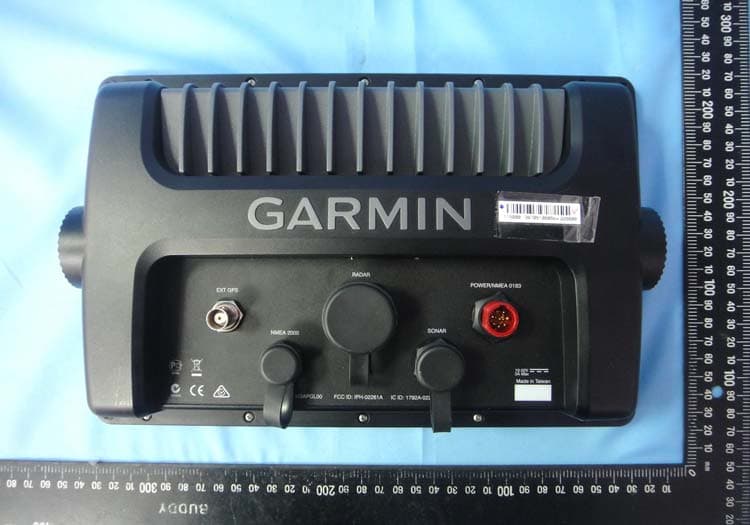
Click to zoom
Application Details
- Equipment Class
- DTS - Digital Transmission System
- Date of Grant
- Dec 11, 2013
- Application Purpose
- Original Equipment
- Date of Application
- Dec 11, 2013
- Equipment Note
- Marine Chartplotter with WLAN
- Frequency Range
- 2412.00000000 - 2462.00000000
- Company
- Garmin International Inc
- Country
- United States
Documents & Files
Document Text
Text extracted from the exhibit documents filed with the FCC. Open a document above to read the original.
Users Manual
GPSMAP ® 800 and 1000 Series Installation Instructions Important Safety Information WARNING See the Important Safety and Product Information guide in the product box for product warnings and other important information. When connecting the power cable, do not remove the in-line fuse holder. To prevent the possibility of injury or product damage caused by fire or overheating, the appropriate fuse must be in place as indicated in the product specifications. In addition, connecting the power cable without the appropriate fuse in place will void the product warranty. CAUTION Always wear safety goggles, ear protection, and a dust mask when drilling, cutting, or sanding. NOTICE When drilling or cutting, always check what is on the opposite side of the surface. Registering Your Device Help us better support you by completing our online registration today. •Go to http://my.garmin.com. •Keep the original sales receipt, or a photocopy, in a safe place. Contacting Garmin Product Support •Go to www.garmin.com/support and click Contact Support for in-country support information. •In the USA, call (913) 397.8200 or (800) 800.1020. •In the UK, call 0808 2380000. •In Europe, call +44 (0) 870.8501241. Tools Needed •Drill and drill bits •#2 Phillips screwdriver •Jigsaw or rotary tool •File and sandpaper •Marine sealant (optional) Mounting Considerations NOTICE This device should be mounted in a location that is not exposed to extreme temperatures or conditions. The temperature range for this device is listed in the product specifications. Extended exposure to temperatures exceeding the specified temperature range, in storage or operating conditions, may cause device failure. Extreme-temperature-induced damage and related consequences are not covered by the warranty. Using the included hardware and template, you can mount the device using one of two methods. You can use the included bracket and hardware to bail mount the device, or you can use the included template and hardware to flush mount the device in the dashboard. When selecting a mounting location, you should observe these considerations. •The location should provide optimal viewing as you operate your boat. •The location should allow for easy access to all device interfaces, such as the keypad, touchscreen, and card reader, if applicable. •The location must be strong enough to support the weight of the device and protect it from excessive vibration or shock. •To avoid interference with a magnetic compass, the device should not be installed closer to a compass than the compass-safe distance value listed in the product specifications. •The location must allow room for the routing and connection of all cables. Bail Mounting the Device NOTICE If you are mounting the bracket on fiberglass with screws, it is recommended to use a countersink bit to drill a clearance counterbore through only the top gel-coat layer. This will help to avoid any cracking in the gel-coat layer when the screws are tightened. Stainless-steel screws may bind when screwed into fiberglass and overtightened. Garmin ® recommends applying an anti-seize lubricant to the screws before installing them. You can use the included bracket to bail mount the device on a flat surface. 1 Using the bail-mount bracket À as a template, mark the pilot holes Á . 2 Using a 3 mm ( 1 / 8 in.) drill bit, drill the pilot holes. 3 Using the included screws  , secure the bail-mount bracket to the mounting surface. 4 Install the bail-mount knobs à on the sides of the device. 5 Place the device in the bail-mount bracket and tighten the bail-mount knobs. Flush Mounting the Device NOTICE Be careful when cutting the hole to flush mount the device. There is only a small amount of clearance between the case and the mounting holes, and cutting the hole too large could compromise the stability of the device after it is mounted. If you are mounting the bracket on fiberglass with screws, it is recommended to use a countersink bit to drill a clearance counterbore through only the top gel-coat layer. This will help to avoid any cracking in the gel-coat layer when the screws are tightened. October 2013 190-01658-02_0APrinted in Taiwan Stainless-steel screws may bind when screwed into fiberglass and overtightened. Garmin recommends applying an anti-seize lubricant to the screws before installing them. The included template and hardware can be used to mount the device in your dashboard. 1 Trim the template and make sure it fits in the location where you want to mount the device. 2 Remove the protective liner from the back of the template and adhere it to the location where you want to mount the device. 3 Using a 9.5 mm ( 3 / 8 in.) drill bit, drill one or more of the holes inside the corners of the solid line on the template to prepare the mounting surface for cutting. 4 Using a jigsaw or rotary tool, cut the mounting surface along the inside of the solid line indicated on the template. 5 Place the device in the cutout to test the fit. 6 If necessary, use a file and sandpaper to refine the size of the cutout. 7 After the device fits correctly in the cutout, ensure the mounting holes on the device line up with the pilot holes on the template. 8 If the mounting holes on the device do not line up, mark the new pilot-hole locations. 9 Using a 3.2 mm ( 1 / 8 in.) drill bit, drill the pilot holes. 10 Remove the template from the mounting surface. 11 If you will not have access to the back of the device after you mount it, connect all necessary cables to the device before placing it into the cutout. 12 If necessary, cover unused connectors with the attached weather caps to prevent corrosion of the metal contacts. 13 Install the foam gasket À on the back of the device. The pieces of the rubber gasket have adhesive on the back. Make sure you remove the protective liner before installing them on the device. 14 Place the device in the cutout. 15 Secure the device to the mounting surface using the included screws Á . 16 Install the …
Text truncated - open the document above for the full version.
Users Manual
GPSMAP ® Owner’s Manual August 2013190-01658-00_0APrinted in Taiwan DRAFT All rights reserved. Under the copyright laws, this manual may not be copied, in whole or in part, without the written consent of Garmin. Garmin reserves the right to change or improve its products and to make changes in the content of this manual without obligation to notify any person or organization of such changes or improvements. Go to www.garmin.com for current updates and supplemental information concerning the use of this product. Garmin ® , the Garmin logo, BlueChart ® , g2 Vision ® , and MapSource ® are trademarks of Garmin Ltd. or its subsidiaries, registered in the USA and other countries. echoMAP™, GXM™, and HomePort™ are trademarks of Garmin Ltd. or its subsidiaries. These trademarks may not be used without the express permission of Garmin. The Bluetooth ® word mark and logos are owned by the Bluetooth SIG, Inc. and any use of such marks by Garmin is under license. iOS ® is a registered trademark of Cisco Systems, Inc. used under license by Apple Inc. microSD™ is a trademark of SD-3C, LLC. NMEA ® , NMEA 2000 ® , and the NMEA 2000 logo are registered trademarks of the National Marine Electronics Association. SiriusXM ® is a registered trademark of SiriusXM Radio Inc. All other trademarks and copyrights are the property of their respective owners. Other trademarks and trade names are those of their respective owners. DRAFT Table of Contents Introduction ................................................................1 Device Front View................................................................. 1 Device Keys.....................................................................1 Downloading the Manuals..................................................... 1 GPS Satellite Signals............................................................ 1 Adjusting the Backlight.......................................................... 1 Adjusting the Color Mode...................................................... 1 Customizing the Home Screen.............................................. 1 Inserting Memory Cards........................................................ 1 Charts and 3D Chart Views....................................... 1 Navigation Chart and Offshore Fishing Chart........................2 Zooming In and Out of the Chart..................................... 2 Panning the Chart with the Keys..................................... 2 Selecting an Item on the Map Using the Device Keys.....2 Chart Symbols................................................................. 2 Viewing Location and Object Information on a Chart...... 2 Navigating to a Point on the Chart...................................3 Viewing Details about Navaids........................................ 3 Premium Charts...............................................................3 Viewing Tide Station Information............................... 3 Showing Satellite Imagery on the Navigation Chart...4 Viewing Aerial Photos of Landmarks......................... 4 Automatic Identification System............................................ 4 AIS Targeting Symbols.................................................... 4 Heading and Projected Course of Activated AIS Targets.............................................................................4 Showing AIS Vessels on a Chart or 3D Chart View........ 5 Activating a Target for an AIS Vessel.............................. 5 Viewing Information about a Targeted AIS Vessel.... 5 Deactivating a Target for an AIS Vessel.................... 5 Viewing a List of AIS Threats...........................................5 Setting the Safe-Zone Collision Alarm.............................5 AIS Distress Signals........................................................ 5 Navigating to a Distress Signal Transmission............5 AIS Distress Signal Device Targeting Symbols......... 5 Enabling AIS Transmission Test Alerts......................5 Turning Off AIS Reception...............................................5 Chart and 3D Chart View Settings.........................................6 Waypoints and Tracks Settings on the Charts and Chart Views............................................................................... 6 Other Vessels Settings on the Charts and Chart Views.. 6 AIS Display Settings.................................................. 6 Navigation and Fishing Chart Setup................................ 6 Overlay Numbers Settings...............................................6 Editing the Data Fields...............................................6 Showing a Navigation Inset............................................. 7 Chart Appearance Settings..............................................7 Fish Eye 3D Settings....................................................... 7 Navigation with a Chartplotter..................................7 Basic Navigation Questions...................................................7 Destinations........................................................................... 8 Searching for a Destination by Name.............................. 8 Selecting a Destination Using the Navigation Chart........ 8 Searching for a Destination Using Nav Info.....................8 Searching for a Marine Services Destination...................8 Courses................................................................................. 8 Setting and Following a Direct Course Using Go To....... 8 Setting and Following a Course Using Auto Guidance....8 Autopilot Navigation.........................................................8 Stopping Navigation.............................................................. 9 Waypoints ..............................................................................9 Marking Your Present Location as a Waypoint................9 Creating a Waypoint at a Different Location.................... 9 Marking and Starting Navigation to an MOB Location.....9 Viewing a List of al…
Text truncated - open the document above for the full version.
Users Manual
www.garmin.com © 2013 Garmin Ltd. or its subsidiaries November 2013 190-00720-32_0B Printed in Taiwan Important Safety and Product Information ......................................................................................................................................2 Informations importantes sur le produit et la sécurité .....................................................................................................................3 Informazioni importanti sulla sicurezza e sul prodotto ....................................................................................................................4 Wichtige Sicherheits- und Produktinformationen ............................................................................................................................4 Información importante sobre el producto y tu seguridad ..............................................................................................................5 Informações Importantes de Segurança e do Produto ...................................................................................................................6 Informações Importantes sobre a Segurança e o Produto ............................................................................................................7 Belangrijke veiligheids- en productinformatie .................................................................................................................................8 Vigtige sikkerheds- og produktinformationer ..................................................................................................................................9 Tärkeitä turvallisuus- ja tuotetietoja ................................................................................................................................................9 Viktig sikkerhets- og produktinformasjon ......................................................................................................................................10 Viktig säkerhets- och produktinformation ......................................................................................................................................11 Ważne informacje dotyczące bezpieczeństwa i produktu ............................................................................................................12 Důležité bezpečnostní informace a informace o produktu ............................................................................................................13 Правила техники безопасности и сведения об изделии ...............................................................................................................................................................13 Važne informacije o proizvodu i sigurnosti ...................................................................................................................................14 Σημαντικές πληροφορίες για την ασφάλεια και το προϊόν ...........................................................................................................15 Önemli Güvenlik ve Ürün Bilgileri .................................................................................................................................................16 Informasi Penting Tentang Keselamatan dan Produk ..................................................................................................................17 Maklumat Penting Keselamatan dan Produk ...............................................................................................................................17 重要安全和产品信息 ..............................................................................................................................................................18 重要安全與產品資訊 ..............................................................................................................................................................19 安全および製品に関する警告と注意事項 .......................................................................................................................19 2 Important Safety and Product Information WarnIng Failure to avoid the following potentially hazardous situations could result in an accident or collision resulting in death or serious injury. Operation Warnings • You are responsible for the safe and prudent operation of your vessel. This device is a tool that will enhance your capability to operate your vessel. It does not relieve you from the responsibility of safely operating your vessel. Avoid navigational hazards and never leave the helm unattended. • Use this device only as a navigational aid. Do not attempt to use the device for any purpose requiring precise measurement of direction, distance, location, or topography. • Always be prepared to promptly regain control of the vessel. Use caution near hazards in the water, such as docks, pilings and other vessels. • If the device has navigating capabilities, when navigating, carefully compare information displayed on the device to all available navigation sources, including information from visual sightings, local waterway rules and restrictions, and maps. For safety, always resolve any discrepancies or questions before continuing navigation. • If the device uses maps, use the electronic chart in the device only to facilitate, not to replace, the use of authorized government charts. Official government charts and notices to mariners contain all information needed to navigate safely. • If the device provides depth data, it should not be used as the primary means of preventing grounding or collision. Supplement depth data readings with information from applicable paper charts and visual indicators. Always operate the vessel at slow speeds if you suspect shallow water or submerged objects. Failure to heed this warning could lead to vessel damage or personal injury. • If the device has video input capabilities, do not attempt to operate or watch video input while operating or navigating yo…
Text truncated - open the document above for the full version.
External Photos
1 of 2 External Photos Model Number: M3APGL00 FCC ID: IPH-02261A 2 of 2 EUT Photo 1 ) EUT Photo 2 )
ID Label/Location Info
SONAR POWER/NMEA 0183 ETHERNET NMEA 2000 EXT GPS Made in Taiwan 10-32V 3A Max N20233 M/N: M3APGL00FCC ID: IPH-02261AIC: 1792A-02261A
Internal Photos
1 of 7 Internal Photos Model Number: M3APGL00 FCC ID: IPH-02261A 2 of 7 EUT Photo 1 ) EUT Photo 2 ) 3 of 7 EUT Photo 3 ) EUT Photo 4 ) Wi-Fi ANT. 4 of 7 EUT Photo 5 ) EUT Photo 6 ) 5 of 7 EUT Photo 7 ) EUT Photo 8 ) 6 of 7 EUT Photo 9 ) EUT Photo 10 ) 7 of 7 EUT Photo 11 ) EUT Photo 12 )
Test Report
A Test Lab Techno Corp. FCC 47 CFR PART 15 SUBPART C Product Type : Low Power Transmitter Applicant : Garmin International Inc. Address : 1200 E., 151st. Street, Olathe, Kansas, United States, 66062 Trade Name : GARMIN Model Number : M3APGL00 Test Specification : FCC 47 CFR PART 15 SUBPART C: Oct., 2012 Canada RSS-210 ISSUE 8: Dec., 2010 Canada RSS-Gen ISSUE 3: Dec., 2010 ANSI C63.4:2009 Receive Date : Oct. 23, 2013 Test Period : Oct. 29~Nov. 01, 2013 Issue Date : Nov. 28, 2013 Issue by A Test Lab Techno Corp. No. 140-1, Changan Street, Bade City, Taoyuan County 334, Taiwan R.O.C. Te l:+886-3-2710188 / Fax:+886-3-2710190 T aiwan Accreditation Foundation accreditation number: 1330 Note: This report shall not be reproduced except in full, without the written approval of A Test Lab Techno Corp. This document may be altered or revised by A Test Lab Techno Corp. personnel only, and shall be noted in the revision section of the document. The client should not use it to claim product endorsement by TAF, or any government agencies. The test results in the report only apply to the tested sample. Report Number: 1311FR11-01 1 of 48 A Test Lab Techno Corp. Revision History Rev. Issue Date Revisions Revised By 00 Nov. 20, 2013 Initial Issue 01 Nov. 28, 2013 Add accessories list. Joyce Liao Report Number: 1311FR11-01 2 of 48 A Test Lab Techno Corp. Verification of Compliance Issued Date: 11/28/2013 Product Type : Low Power Transmitter Applicant : Garmin International Inc. Address : 1200 E., 151st. Street, Olathe, Kansas, United States, 66062 Trade Name : GARMIN Model Number : M3APGL00 FCC ID : IPH-02261A EUT Rated Voltage : DC 10–32V, 3A Test Voltage : DC 24V Applicable Standard : FCC 47 CFR PART 15 SUBPART C: Oct., 2012 Canada RSS-210 ISSUE 8: Dec., 2010 Canada RSS-Gen ISSUE 3: Dec., 2010 ANSI C63.4:2009 Test Result : Complied Performing Lab. : A Test Lab Techno Corp. No. 140-1, Changan Street, Bade City, Taoyuan County 334, Taiwan R.O.C. Te l:+886-3-2710188 / Fax:+886-3-2710190 T aiwan Accreditation Foundation accreditation number: 1330 http://www.atl-lab.com.tw/e-index.htm The above equipment was tested by A Test Lab Techno Corp. The test data, data evaluation, test procedures, and equipment configurations shown in this report were made in accordance with the procedures given in ANSI C63.4: 2009 and the energy emitted by the sample tested as described in this report is in compliance with the requirements of FCC Rules Part 15.207, 15.209, 15.247 . The test results of this report relate only to the tested sample identified in this report. Approved By : Reviewed By : (Manager) (Cran Yang) (Testing Engineer) (Fly Lu) Report Number: 1311FR11-01 3 of 48 TABLE OF CONTENTS 1 General Information ....................................................................................................................................... 6 2 EUT Description ............................................................................................................................................. 7 3 Test Methodology .......................................................................................................................................... 8 3.1. Mode of Operation.................................................................................................................................. 8 3.2. EUT Exercise Software.......................................................................................................................... 8 3.3. Configuration of Test System Details ..................................................................................................... 9 3.4. Test Site Environment ............................................................................................................................ 9 4 Conducted Emission Measurement ........................................................................................................... 10 4.1. Limit ...................................................................................................................................................... 10 4.2. Test Instruments ................................................................................................................................... 10 4.3. Test Setup............................................................................................................................................. 10 4.4. Test Procedure ......................................................................................................................................11 4.5. Test Result.............................................................................................................................................11 5 Radiated Emission Measurement............................................................................................................... 12 5.1. Limit ...................................................................................................................................................... 12 5.2. Test Instruments ................................................................................................................................... 12 5.3. Setup .................................................................................................................................................... 13 5.4. Test Procedure ..................................................................................................................................... 14 5.5. Test Result............................................................................................................................................ 16 6 Maximum Conducted Output Power Measurement.................................................................................. 21 6.1. Limit ...................................................................................................................................................... 21 6.2. Test Setup........…
Text truncated - open the document above for the full version.
Test Setup Photos
Part 15C Test Setup Photographs Radiated Emissions Test Configuration: Below 1GHz _ Front View Below 1GHz _ Rear View A Test Lab Techno Corp. Report Number: 1311FR11-01 1 of 2 Above 1GHz _ Front View Above 1GHz _ Rear View A Test Lab Techno Corp. Report Number: 1311FR11-01 2 of 2
Contact Information
Applicant
Ben Karsak(Manager, Compliance Engineering)
Test Firm
Eurofins E&E Wireless Taiwan Co., LtdFly LU
Technical Specifications
| # | Rule Parts | Frequency Range | Power Output |
|---|---|---|---|
| 1 | 15C | 2.41 GHz - 2.46 GHz | 212.00 mW |
Other Applications from Garmin International Inc
IPH-05170
Aug 05, 2026Transceiver
Equipment Class
DTS - Digital Transmission SystemIPH-A5192
Jul 21, 2026Fitness product
Equipment Class
DXX - Part 15 Low Power Communication Device TransmitterIPH-0P3039
Jul 07, 2026Outdoor Product
Equipment Class
DTS - Digital Transmission SystemIPH-04286
Jul 06, 2026Digital Transmission System Transceiver
Equipment Class
DTS - Digital Transmission SystemIPH-04292
Jul 06, 2026Digital Transmission System Transceiver
Equipment Class
TNB - Licensed Non-Broadcast Station Transmitter