IPH-03545Engine Buss Adapter with RF
Garmin International Inc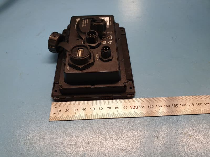
Click to zoom
Application Details
- Equipment Class
- DXX - Part 15 Low Power Communication Device Transmitter
- Date of Grant
- Mar 08, 2020
- Application Purpose
- Original Equipment
- Date of Application
- Mar 08, 2020
- Equipment Note
- Engine Buss Adapter with RF
- Frequency Range
- 2402.00000000 - 2480.00000000
- Company
- Garmin International Inc
- Country
- United States
Documents & Files
Document Text
Text extracted from the exhibit documents filed with the FCC. Open a document above to read the original.
Users Manual
Important Safety and Product Information......................................................................................... 2 Informations importantes sur le produit et la sécurité.........................................................................2 Informazioni importanti sulla sicurezza e sul prodotto........................................................................3 Wichtige Sicherheits- und Produktinformationen............................................................................... 3 Información importante sobre el producto y tu seguridad.................................................................. 3 Informações importantes sobre segurança e o produto.....................................................................4 Belangrijke veiligheids- en productinformatie.....................................................................................4 Vigtige produkt- og sikkerhedsinformationer...................................................................................... 5 Tärkeitä turvallisuus- ja tuotetietoja....................................................................................................5 Viktig sikkerhets- og produktinformasjon........................................................................................... 5 Viktig säkerhets- och produktinformation........................................................................................... 5 Правила техники безопасности и сведения об изделии............................................................... 6 重要安全和产品信息...............................................................................................6 © 2016 YAMAHA Motor Co., LTD. Printed in Taiwan March 2018 Yamaha Motor Co., LTD. 2500 Shingai, Iwata, Shizuoka 438-8501, Japan 190-02076-92_0C 6YD-2 818N-00 IMPORTANT SAFETY AND PRODUCT INFORMATION WARNING Failure to heed the following warnings could result in an accident or collision resulting in death or serious injury. Marine Operation Warnings •You are responsible for the safe and prudent operation of your vessel. This device is a tool that will enhance your capability to operate your vessel. This device does not relieve you from the responsibility of safely operating your vessel. Avoid navigational hazards and never leave the helm unattended. • Use this device only as a navigational aid. Do not attempt to use the device for any purpose requiring precise measurement of direction, distance, location, or topography. • Always be prepared to promptly regain control of the vessel. Use caution near hazards in the water, such as docks, pilings and other vessels. • If the device has navigating capabilities, when navigating, carefully compare information displayed on the device to all available navigation sources, including information from visual sightings, local waterway rules and restrictions, and maps. For safety, always resolve any discrepancies or questions before continuing navigation. • If the device uses maps, use the electronic chart in the device only to facilitate, not to replace, the use of authorized government charts. Official government charts and notices to mariners contain all information needed to navigate safely. • If the device provides depth data, it should not be used as the primary means of preventing grounding or collision. Supplement depth data readings with information from applicable paper charts and visual indicators. Always operate the vessel at slow speeds if you suspect shallow water or submerged objects. Failure to heed this warning could lead to vessel damage or personal injury. • If the device has video input capabilities, do not attempt to operate or watch video input while operating or navigating your vessel. Operating or watching the video input while the vessel is moving could cause an accident or collision resulting in property damage, serious injury, or death. Battery Warnings The device uses an internal, non-user-replaceable battery for various purposes, such as the real-time clock. If these guidelines are not followed, batteries may experience a shortened life span or may present a risk of damage to the device, fire, chemical burn, electrolyte leak, and/or injury. • Do not remove or attempt to remove the non-user-replaceable battery. Hearing Damage Warning Listening to the stereo at high volume can cause damage to your hearing. NOTICE Failure to heed the following notice could result in personal or property damage, or negatively impact the device functionality. Battery Notice Contact your local waste disposal department to dispose of the device/batteries in accordance with applicable local laws and regulations. GPS Notice The navigation device may experience degraded performance if you use it in proximity to any device that uses a terrestrial broadband network operating close to the frequencies used by any Global Navigation Satellite System (GNSS), such as the Global Positioning Service (GPS). Use of such devices may impair reception of GNSS signals. Product Environmental Programs Information about the Garmin ® product recycling program and WEEE, RoHS, REACH, and other compliance programs can be found at www.garmin.com/aboutGarmin/environment. Declaration of Conformity Hereby, Garmin declares that this product is in compliance with the Directive 2014/53/EU. The full text of the EU declaration of conformity is available at the following internet address: www.garmin.com/compliance. Innovation, Science and Economic Development Canada Compliance This device complies with Innovation, Science and Economic Development Canada license- exempt RSS standard(s). Operation is subject to the following two conditions: (1) this device may not cause interference, and (2) this device must accept any interference, including interference that may cause undesired operation of the device. Radio Frequency Radiation Exposure This device is a mobile transmitter and receiver that uses an internal antenna to send and receive low levels of radio freque…
Text truncated - open the document above for the full version.
Users Manual
CL 5 DISPLAY CL0 QUICK START MANUAL 6YD-XXXXU-E0 Introduction WARNING See the Important Safety and Product Information guide in the product box for product warnings and other important information. Device Overview À Touchscreen Á Automatic backlight sensor  Power key Engine Data Screen The engine data screen appears when you turn on the device. This screen varies based on the engine network and throttle controller. From this screen, you can access other data screens and the home screen. To open a different screen, swipe the screen right or left, or select the arrows on either side of the screen. À Data fields Hold to replace the data. Á Current time Hold to view trip data.  Press to set the joystick button Set Point functions (Helm Master ® ). à Tank level information Hold a tank to view detailed tank level sensor information. Ä GPS signal strength Select to set the Fish Point high RPM limit (Helm Master). Select to set the trolling speed (Command Link Plus ® ). Å Data fields Hold to replace the data. Æ Shift position Ç Tachometer and trim angle Hold to change the background. È Engine information Hold to replace the data and change the gauge appearance. Engine Alert Icons Red icons indicate engine abnormalities. NOTICE Consult your Yamaha ® dealer if the problem cannot be located and corrected. Low cooling water pressure. Low oil pressure. Stop the engine. Check the engine oil level, and add more oil if necessary. NOTICE Do not continue to run the engine if this indicator is on. Serious engine damage will occur. Engine overheating. Stop the engine immediately. Check the cooling water inlet, and clear it if it is blocked. NOTICE Do not continue to run the engine if this indicator is on. Serious engine damage will occur. Low battery voltage. Check the battery and battery connections, and tighten all loose battery connections. Return to port soon if tightening the battery connections does not increase the battery voltage. Consult your Yamaha dealer immediately. NOTE: Do NOT stop the engine when this alert is on. If you do, you may not be able to restart the engine. Water in the fuel. Water has collected in the fuel filter (fuel separator). Stop the engine immediately and consult the engine manual to drain the water from the fuel filter. NOTE: Gasoline mixed with water might cause damage to the engine. Check engine/maintenance alert. Consult your Yamaha dealer immediately. The check engine alert also appears when more than 100 hours have elapsed since the previous maintenance. Engine alert notification. (Helm Master) Engine emission issue. Engine Condition Icons Orange icons indicate engine conditions. Yamaha security system is on. Engines are under synchronization control. Engines are warming up. GPS Signal Strength Icons The icons shown in the upper-right of the engine screen indicate the GPS signal strength. GPS satellite signal strength No GPS satellite signal 2Quick Start Manual Pairing the Remote Control to the CL0 Device You must pair the remote control to the CL0 device before you can use the CL0 device. 1 Turn on the CL0 device. The device turns on in paring mode. If it is not in paring mode, hold the CL0 power button for 3 seconds. 2 On the remote control, hold the MENU and keys. The device beeps until the remote control and device are paired. CL0 Remote Control Quick Start Manual3 À Turn to highlight. Push to select Á Returns to previous the screen or menu.  Opens the menu for that page. à Hold to assign a shortcut key to the current page. Press to open the assigned page.. Ä Press to adjust the backlight brightness BACK MENU 12 Yamaha Autopilot WARNING You are responsible for the safe and prudent operation of your vessel. The autopilot is a tool that enhances your capability to operate your boat. It does not relieve you of the responsibility of safely operating your boat. Avoid navigational hazards and never leave the helm unattended. Always be prepared to promptly regain manual control of your boat. Learn to operate the autopilot on calm and hazard-free open water. Use caution when operating the autopilot near hazards in the water, such as docks, pilings, and other boats. The autopilot system continuously adjusts the steering of your boat to maintain a constant heading (heading hold). When the chartplotter is connected to a compatible Yamaha autopilot system, you can view the autopilot information using the Yamaha autopilot screen and overlay bar ( Yamaha Autopilot, page 2). For information about compatible Yamaha autopilot systems, contact your Yamaha dealer. When the chartplotter is connected to a compatible Garmin ® autopilot system, you can engage and control the autopilot from the chartplotter (Autopilot, page 38). For information about compatible Garmin autopilot systems, go to garmin.com. Actual heading Intended heading (heading the autopilot is steering toward) Yamaha Autopilot Settings From a Yamaha engine screen, select Menu > Autopilot Setting. Pattern Set: Allows you to select an autopilot pattern. Direction: Sets a port or starboard direction for the pattern. Spacing: Sets the spacing for the pattern. Length : Sets the length of the pattern. Amplitude: Sets the angle for the zigzag pattern. Initial Radius: Sets the radius of the spiral pattern. Final Track Point Mode: Sets the mode for the autopilot when it reaches the end of a route. Offset Distance: Sets an offset distance to navigate parallel to a route. Yamaha Autopilot Screen Yamaha Autopilot Overlay Bar Autopilot mode Actual heading Intended heading (heading the autopilot is steering toward) Opens the full autopilot screen and menu WARNING Only replace batteries with AAA batteries. Using other batteries presents a risk of fire or explosion. Contact your local waste disposal department to dispose of the device/batteries in accordance with applicable local laws and regulations 4Quick Start Manual © 2017–2019 YAMAHA Motor Co., LTD or its subsidiaries Yamaha ® , the Yamaha logo, Command Link Plus ® , and Helm Ma…
Text truncated - open the document above for the full version.
Cover Letter(s)
A3545 and C3545 have identical transmitter characteristics but differ in the following ways Model differences The CL0-1 (C3545) and CL5 (A3545) use the same PCB, Power and RF circuitry. The model differences are different in the following ways: 1) Display: CL0-1 does not have an integral touch screen display 2) HDMI: CL5 does not have an HDMI output During testing both models were tested for EMI/EMC requirements separately. Both models have identical PCB layouts and signal routing with respect to the transmitters installed. During RF testing both models were initially investigated and determined to have identical transmitter characteristics. Transmitter testing was then performed only on the CL5 to demonstrate compliance.
Cover Letter(s)
SUBJECT: Confidentiality Request Pursuant to FCC 47 CRF 0.457(d) and 0.459 and IC RSP-100, Section 12.4, the applicant requests that a part of the application be held confidential. Exhibits Long-Term Confidentiality Short-Term Confidentiality Block Diagram Long Term / Permanent Schematic Long Term / Permanent Operation Description/Theory of Operation Long Term / Permanent Tune-Up Procedure Long Term / Permanent Parts List/BOM Long Term / Permanent External Photos Short Term Internal Photos Short Term Test Setup Photos Short Term User’s Manual Short Term Garmin International, Inc. has spent substantial effort in developing this product and it is one of the first of its kind in industry. Having the subject information easily available to "competition" would negate the advantage they have achieved by developing this product. Not protecting the details of the design will result in financial hardship. Long-Term Confidentiality: The applicant requests the exhibits listed above as permanently confidential be permanently withheld from public review due to materials that contain trade secrets and proprietary information not customarily released to the public. NOTE for Industry Canada Applications: IC currently only distinguishes Permanent Confidentiality exhibits as shown above. Short Term confidentiality is not considered applicable to IC applications. Sincerely, Hadid Jones Senior Compliance Engineer
External Photos
C3545 External Photos Figure 1 – Rear Figure 2 – Left Figure 3 – Right Figure 4 – Front Figure 5 – Bottom Figure 6 - Top
ID Label/Location Info
A3545 Label location FCC ID: IPH-03545 IC: 1792A-03545 M/N C3545
Internal Photos
M/N: C3545 (without display) Internal Photos Figure 1 - M/N: C3545 PCB Front Figure 2 - M/N: C3545 PCB Rear Figure 3- M/N: C3545 Transceiver IC and Antenna M/N: A3545 (with display) Internal Photos Figure 4 - M/N: A3545 PCB Front Figure 5 - M/N: A3545 PCB Rear Figure 6 - M/N: A3545 Antenna and TX Chip
Parts List/Tune Up Info
Part Number Lvl MC Bub Comment Description 012-03545-20 L1 PCB Assy, CL0 012-03545-80 L2 - - . PCB Assy, GMI50/CL5/CL0/CL0G, Analog 334-00012-12 L3 - - . Conn,Shrd Hdr,1.5mm,STR.,12 pos. 500-00087-00 L3 - - . IC,Quad,OP-AMP,SSOP,26V 500-00475-01 L3 - - . IC,10Bit,8-Ch,ADC,MCP3008,SOIC-16 681-00038-00 L3 - - . Diode,Schottky,40V,0.5A,SOD123 681-00091-00 L3 - - . Dio,Schottky,Dual,Lo Vf,RB480Y 684-00021-00 L3 - - . ESD/TVS,Low-Cap,4-Line,SC70-6 805-P6104-KC L3 - - . Cap,Cer,0.1uF,10%,16V,X5R,0402 805-P6105-KA L3 - - . Cap,Cer,1uF,10%,10V,X5R,0402 900-01002-F0 L3 - - . Res,Chip,10K,1%,1/4W ,1206 900-0402R-F0 L3 - - . Res, Chip, 402 Ohm, 1%, 1/4W , 1206 907-00000-J0 L3 - - . Res,Chip,0 Ohm Jumper,0402 907-00103-J0 L3 - - . Res,Chip,10K,5%,1/20W ,0402 907-00472-J0 L3 - - . Res,Chip,4.7 K,5%,1/20W ,0402 908-00000-J0 L3 - - . Res,Chip,0 Ohm Jumper,0603 915-00000-J0 L3 - - . Res,Chip,0 ohm,Jumper,0201 012-03545-82 L2 - - . PCB Assy, GMI50/CL5/CL0/CL0G, Dropdtct 500-00662-00 L3 - - . IC,OpAmp,R-Rout,single 522-4B008-S1 L3 - - . IC,TC7SZ08,2-IN AND,SSOP5 681-00113-00 L3 - - . Diode,Schottky,5A,40V,SMC 805-P6104-KC L3 - - . Cap,Cer,0.1uF,10%,16V,X5R,0402 805-R0110-04 L3 - - . Cap,Cer,4700pF,5%,50V,X7R,0402 814-00338-MF L3 - - . Cap,Elctlt,3300uf,20%,50V,Rdl 900-00000-J0 L3 - - NOT USED Res,Chip,0 Ohm,1/4W ,1206 906-A0151-J0 L3 - - . Res,150 Ohm,5%,1/2W ,2010 907-00473-J0 L3 - - . Res,Chip,47K,5%,1/20W ,0402 907-00474-J0 L3 - - . Res,Chip,470K,5%,1/20W ,0402 908-03742-F0 L3 - - . Res,Chip,37.4K,1%,1/16W ,0603 908-07151-F0 L3 - - . Res,Chip,7.15K,1%,1/16W ,0603 012-03545-84 L2 - - . PCB Assy, GMI50/CL5/CL0/CL0G, HDMI 330-01026-01 L3 - - PURCH SEL J701 Conn,Rcpt,HDMI,Type A,Vert,19 Pin,SMT Contacts & TH Shell 330-01026-07 L3 - - PURCH SEL J701 CONN,RCPT,HDMI,TYPE A,VERT,19 PIN,SMT CONTACTS & TH SHELL 500-01290-00 L3 - - . IC,HDMI TX Port Protection/Lvl Shift,TPD12S521,TSSOP38 595-00224-03 L3 - - . IC,HDMI TX,ADV7511W ,64LQFP 670-00037-03 L3 - - . Xstr,MOSFET,P-Ch,8 Vds,1.8 Vgs,SOT23 670-00051-04 L3 - - . Xstr, N-Ch, 20VDS, 1.65VGS, 210mA, SOT-723 684-00017-00 L3 - - . TVS,Prot,4-Line,3.3v,SLP2116P8 730-00011-12 L3 - - . Ferrite Bead, RF, 120 Ohm, 0603 745-0B103-M0 L3 - - . Idctr,fxd,ww,10uH,20%,1007 805-C6101-JF L3 - - . Cap,Cer,100pF,5%,50V,NPO,0402 805-C6220-JF L3 - - NOT USED Cap,Cer,22pF,5%,50V,NPO,0402 805-P4106-MB L3 - - . Cap,Cer,10uF,20%,6.3V,X5R,0603 805-P6104-KA L3 - - . Cap,Cer,0.1uF,10%,10V,X5R,0402 805-P6104-KC L3 - - . Cap,Cer,0.1uF,10%,16V,X5R,0402 860-00001-02 L3 - - . Cap Array,4 Elem,0508,10pF 860-00001-02 L3 - - NOT USED Cap Array,4 Elem,0508,10pF 907-00103-J0 L3 - - . Res,Chip,10K,5%,1/20W ,0402 907-00105-J0 L3 - - . Res,Chip,1M,5%,1/20W ,0402 907-00162-J0 L3 - - . Res,Chip,1.6K,5%,1/20W ,0402 907-00472-J0 L3 - - . Res,Chip,4.7 K,5%,1/20W ,0402 907-00473-J0 L3 - - . Res,Chip,47K,5%,1/20W ,0402 907-01002-F0 L3 - - . Res,Chip,10.0K,1%,1/20W ,0402 907-01003-F0 L3 - - . Res,Chip,100K,1%,1/20W ,0402 907-01153-F0 L3 - - . Res,Chip,115K,1%,1/20W ,0402 907-061R9-F0 L3 - - . Res,Chp,61.9 Ohm,1%,1/20W ,0402 907-0825R-F0 L3 - - . Res,Chip,825 Ohm,1%,1/20W ,0402 908-00000-J0 L3 - - . Res,Chip,0 Ohm Jumper,0603 915-00000-J0 L3 - - . Res,Chip,0 ohm,Jumper,0201 915-00102-J0 L3 - - . Res,Chip,1K,1/20W ,5%,0201 915-0051R-J0 L3 - - . Res,Chip,51 Ohm,5%,1/20W ,0201 920-00000-J0 L3 - - . Array Res,0ohms,5%,0402 012-03545-85 L2 - - . PCB Assy, GMI50/CL5/CL0/CL0G, PairFlex 330-00474-06 L3 - - . Conn,.5P.2T Flex,RA,BC,ELP,6CKT 670-00051-04 L3 - - . Xstr, N-Ch, 20VDS, 1.65VGS, 210mA, SOT-723 684-00029-00 L3 - - . TVS,ESD,5V,4 LINE,SOT553 805-B6103-KC L3 - - . Cap,Cer,0.01uF,10%,16V,X7R,0402 805-B6104-KA L3 - - . Cap,Cer,0.1uF,10%,10V,X7R,0402 908-00472-J0 L3 - - . Res,Chip,4.7K,5%,1/16W ,0603 915-00000-J0 L3 - - . Res,Chip,0 ohm,Jumper,0201 012-03545-87 L2 - - . PCB Assy, GMI50/CL5/CL0/CL0G, USB 334-00012-06 L3 - - . Conn,Shrd Hdr,1.5mm,STR.,6 pos. 500-01366-00 L3 - - . IC,Load Switch with Current Limit,2x2 uDFN6 684-00012-03 L3 - - . TVS,ESD Supp 6.0v,SOD-523 684-00021-00 L3 - - . ESD/TVS,Low-Cap,4-Line,SC70-6 746-70024-03 L3 - - . Idctr,Common Mode Choke,0805,USB2.0,47nH 805-P6105-KA L3 - - . Cap,Cer,1uF,10%,10V,X5R,0402 907-01002-F0 L3 - - . Res,Chip,10.0K,1%,1/20W ,0402 907-01003-F0 L3 - - . Res,Chip,100K,1%,1/20W ,0402 907-03922-F0 L3 - - . Res,Chip,39.2K,1%,1/20W ,0402 908-00153-J0 L3 - - NOT USED Res,Chip,15K,5%,1/16W ,0603 909-F0000-00 L3 - - . Res,Chip,0 Ohm,Jumper,0805,2.0A 012-03545-88 L2 - - . PCB Assy, GMI50/CL5/CL0/CL0G, W IFIANTBLE 330-00436-02 L3 - - . Conn,Coax,Low Prof,Recept,RF1 Series,U.FL/MHF I Equiv,SMT 590-00089-00 L3 - - . IC,GNSS/W iFi/BT/ANT+/FM,QFN,MT6630Q 748-482R2-M1 L3 - - . Idctr,WW,Shld,1.6x2.0x1mm,2.2uH,20%,1.31A 751-00038-12 L3 - - GROUP SEL BALUN A Xfmr,RF Balun,2.45GHz,50/50,2012,2.8dBmax 751-00038-13 L3 - - GROUP SEL BALUN B Xfmr,RF Balun,2.45GHz,50/50,2012,3.8dBmax 805-B7102-KA L3 - - . Cap,Cer,1000pF,10%,10V,X7R,0201 805-C70R5-BD L3 - - NOT USED Cap,Cer,0.5pF,+-0.1pF,25V,NP0,0201 805-C7220-JD L3 - - . Cap,Cer,22pF,5%,25V,NPO,0201 805-C7220-JD L3 - - NOT USED Cap,Cer,22pF,5%,25V,NPO,0201 805-C73R3-CD L3 - - . Cap,Cer,3.3pF,+-0.25pF,25V,NP0,0201 805-P4475-KA L3 - - . Cap,CER,4.7uF,10%,10V,X5R,0603 805-P6105-KB L3 - - . Cap,Cer,1uF,10%,6.3V,X5R,0402 805-P7104-KB L3 - - . Cap,Cer,0.1uF,10%,6.3V,X5R,0201 805-PN106-MB L3 - - . Cap,Cer,10uF,20%,6.3V,X5R,0402 915-00101-J0 L3 - - . Res,Chip,100 ohm,1/20W ,5%,0201 915-0022R-J0 L3 - - . Res,Chip,22ohm,1/20W ,5%,0201 915-00473-J0 L3 - - . Res,Chip,47K,5%,1/20W ,0201 915-01002-F0 L3 - - . Res,Chip,10K,1/20W ,1%,0201 012-03545-99 L2 - - . PCB Assy, GMI50/CL5/CL0/CL0G, Common 001-00036-00 L3 - - REFERENCE DOCUMENT Pb-Free Process Required 105-03545-00 L3 - - . PCB, GMI50/CL5/CL0/CL0G 115-02468-01 L3 - - . SMP, FENCE, TELEMATICS BB 115-02468-11 L3 - - . SMP,Lid,front, DriveSmart 61 115-03248-00 L3 - - . SMP,Shield Fence,GMI50/CL5 115-03248-10 L3 - - . SMP,Shield Lid,GMI50/CL5 334-00005-13 L3 - - NOT USED Term Stp,.025"Sq,SR,STR,2Ckt…
Text truncated - open the document above for the full version.
RF Exposure Info
© 2020 RF Exposure Lab, LLC This report shall not be reproduced except in full without the written approval of RF Exposure Lab, LLC. 802 N. Twin Oaks Valley Road, Suite 105 • San Marcos, CA 92069 • U.S.A. TEL (760) 471-2100 • FAX (760) 471-2121 http://www.rfexposurelab.com CERTIFICATE OF COMPLIANCE SAR EVALUATION Garmin International Dates of Test: February 22, 2020 1200 E. 151 st Street Test Report Number: SAR.20200212 Olathe, KS 66062 Revision A This wireless mobile and/or portable device has been shown to be compliant for localized specific absorption rate (SAR) for uncontrolled environment/general exposure limits specified in ANSI/IEEE Std. C95.1-1992 and had been tested in accordance with the measurement procedures specified in IEEE 1528-2013, IEC 62209-2:2010 and IEC 62209-2 Amd 1 (See test report). I attest to the accuracy of the data. All measurements were performed by myself or were made under my supervision and are correct to the best of my knowledge and belief. I assume full responsibility for the completeness of these measurements and vouch for the qualifications of all persons taking them. RF Exposure Lab, LLC certifies that no party to this application is subject to a denial of Federal benefits that includes FCC benefits pursuant to Section 5301 of the Anti-Drug Abuse Act of 1988, 21 U.S.C. 853(a). Jay M. Moulton Vice President Testing Cert. # 2387.01 FCC ID: IPH-03545 IC Certificate: 1792A-03545 Model(s): A3545 Test Sample: Engineering Unit Same as Production Serial Number: 14797270 Equipment Type: Wireless Navigation Monitor Classification: Portable Transmitter Next to Body TX Frequency Range: 2412 – 2462 MHz Frequency Tolerance: ± 2.5 ppm Maximum RF Output: 2450 MHz (b) – 18.50 dB, 2450 MHz (g) – 18.00 dB Conducted Signal Modulation: DSSS, OFDM Antenna Type: Internal Antenna Application Type: Certification FCC Rule Parts: Part 2, 15C KDB Test Methodology: KDB 447498 D01 v06, KDB 248227 v02r02 Industry Canada: RSS-102 Issue 5, Safety Code 6 Maximum SAR Value: 0.17 W/kg Reported Separation Distance: 0 mm Report Number: SAR.20200212 © 2020 RF Exposure Lab, LLC Page 2 of 55 This report shall not be reproduced except in full without the written approval of RF Exposure Lab, LLC. Table of Contents 1. Introduction ........................................................................................................................ 4 SAR Definition [5] ................................................................................................................... 5 2. SAR Measurement Setup ................................................................................................... 6 Robotic System ...................................................................................................................... 6 System Hardware ................................................................................................................... 6 System Electronics ................................................................................................................. 7 Probe Measurement System .................................................................................................. 7 3. Probe and Dipole Calibration .............................................................................................15 4. Phantom & Simulating Tissue Specifications .....................................................................16 Head & Body Simulating Mixture Characterization ................................................................16 5. ANSI/IEEE C95.1 – 1992 RF Exposure Limits [2] ..............................................................17 Uncontrolled Environment .....................................................................................................17 Controlled Environment .........................................................................................................17 6. Measurement Uncertainty .................................................................................................18 7. System Validation..............................................................................................................19 Tissue Verification .................................................................................................................19 Test System Verification ........................................................................................................19 8. SAR Test Data Summary ..................................................................................................20 Procedures Used To Establish Test Signal ...........................................................................20 Device Test Condition ...........................................................................................................20 SAR Data Summary – 2450 MHz Body 802.11b ...................................................................22 9. Test Equipment List ...........................................................................................................23 10. Conclusion ....................................................................................................................24 11. References ....................................................................................................................25 Appendix A – System Validation Plots and Data .......................................................................26 Appendix B – SAR Test Data Plots ...........................................................................................29 Appendix C – SAR Test Setup Photos ......................................................................................31 A ppendix D – Probe Calibration Data Sheets ............................................................................33 Appendix E – Dipole Calibration Data Sheets ...........................................................................44 Appendix F – Phantom Calibration Data Sheets ......…
Text truncated - open the document above for the full version.
RF Exposure Info
Prediction of MPE limit at a given distance Equation from page 18 of OET Bulletin 65, Edition 97-01 where:S = power density P = power input to the antenna G = power gain of the antenna in the direction of interest relative to an isotropic radiator R = distance to the center of radiation of the antenna MODEL - CL0-1 WIFI Maximum peak output power at device output terminal:16.29dBm Cable and Jumper loss:0dB Maximum peak output power at antenna input terminal:16.29dBm Power in mW0.042559841W Single Antenna gain (typical):2dBiIntegral/included Number of Antennae:1 Total Antenna gain (typical):2dBi Antenna Gain (numeric)1.584893192(numeric)Integral/included Prediction distance:0.2m Prediction frequency:2437MHz MPE limit for uncontrolled exposure at prediction frequency:10 W/m^ 2 Power density at prediction frequency:0.134193087 W/m^ 2 Tx On time:1ms Tx period time:1ms Average Factor:100% Average Power density at prediction frequency:0.134193087 W/m^ 2 2 4R PG S =
Test Report
Report reference ID: 373054 – 1TRFWL Page 1 of 29 ONE WORLDOURAPPROVAL Test report 373054 - 1TRFWL Date of issue: August 8, 2019 Applicant: Garmin International Product: MFD and Black Box Remote Models: Variants: CL Model (Wi-Fi) CL0-1 MFD Interface (Interface Unit) - M/N C3545 CL-5 Display (Multi Display Assy.) – M/N A3545 Specifications: FCC 47 CFR Part 15.249 Operation within the bands 902–928 MHz, 2400–2483.5 MHz, 5725–5875 MHZ, and 24.0–24.25 GHz. RSS-210 Issue 10, December 2019 Annex B.10 License-Exempt Radio Apparatus: Category 1 Equipment Report reference ID: 373054 – 1TRFWL Page 2 of 29 Test location Company name Nemko USA, Inc. Address 2210 Faraday Ave, Suite 150 City Carlsbad Province California Postal code 92008 Country USA Telephone +1 760 444 3500 Website www.nemko.com Tested by Andre Martinez, Test Engineer. Reviewed by Chip Fleury Date August 7, 2019 Signature Limits of responsibility Note that the results contained in this report relate only to the items tested and were obtained in the period between the date of initial receipt of samples and the date of issue of the report. This test report has been completed in accordance with the requirements of ISO/IEC 17025. All results contain in this report are within Nemko Canada’s ISO/IEC 17025 accreditation. Copyright notification Nemko Canada Inc. authorizes the applicant to reproduce this report provided it is reproduced in its entirety and for use by the company’s employees only. Any use which a third party makes of this report, or any reliance on or decisions to be made based on it, are the responsibility of such third parties. Nemko Canada Inc. accepts no responsibility for damages, if any, suffered by any third party as a result of decisions made or actions based on this report. © Nemko Canada Inc. Report reference ID: 373054 – 1TRFWL Page 3 of 29 Table of contents Table of contents .......................................................................................................................................................................................................... 3 Section 1. Report summary ................................................................................................................................................................................. 4 1.1 Applicant and manufacturer ......................................................................…
Text truncated - open the document above for the full version.
Contact Information
Applicant
Ben Karsak(Manager, Compliance Engineering)
Test Firm
Nemko USA, Inc. - San Diego EMC DivisionJan Blomgren
[email protected]760-444-3500
Technical Specifications
| # | Rule Parts | Frequency Range | Power Output |
|---|---|---|---|
| 1 | 15C | 2.40 GHz - 2.48 GHz | - |
Other Applications from Garmin International Inc
IPH-05126
Sep 09, 2026Portable Digital Transceiver
Equipment Class
NII - Unlicensed National Information Infrastructure TXIPH-A5126
Sep 09, 2026Portable Digital Transceiver
Equipment Class
NII - Unlicensed National Information Infrastructure TXIPH-04812
Sep 01, 2026Mobile Digital Transceiver
Equipment Class
DTS - Digital Transmission SystemIPH-A04825
Sep 01, 2026Marine Stereo
Equipment Class
DSS - Part 15 Spread Spectrum TransmitterIPH-B04825
Sep 01, 2026Marine Stereo
Equipment Class
DSS - Part 15 Spread Spectrum Transmitter