IPH-03915Low Power Transmitter
Garmin International Inc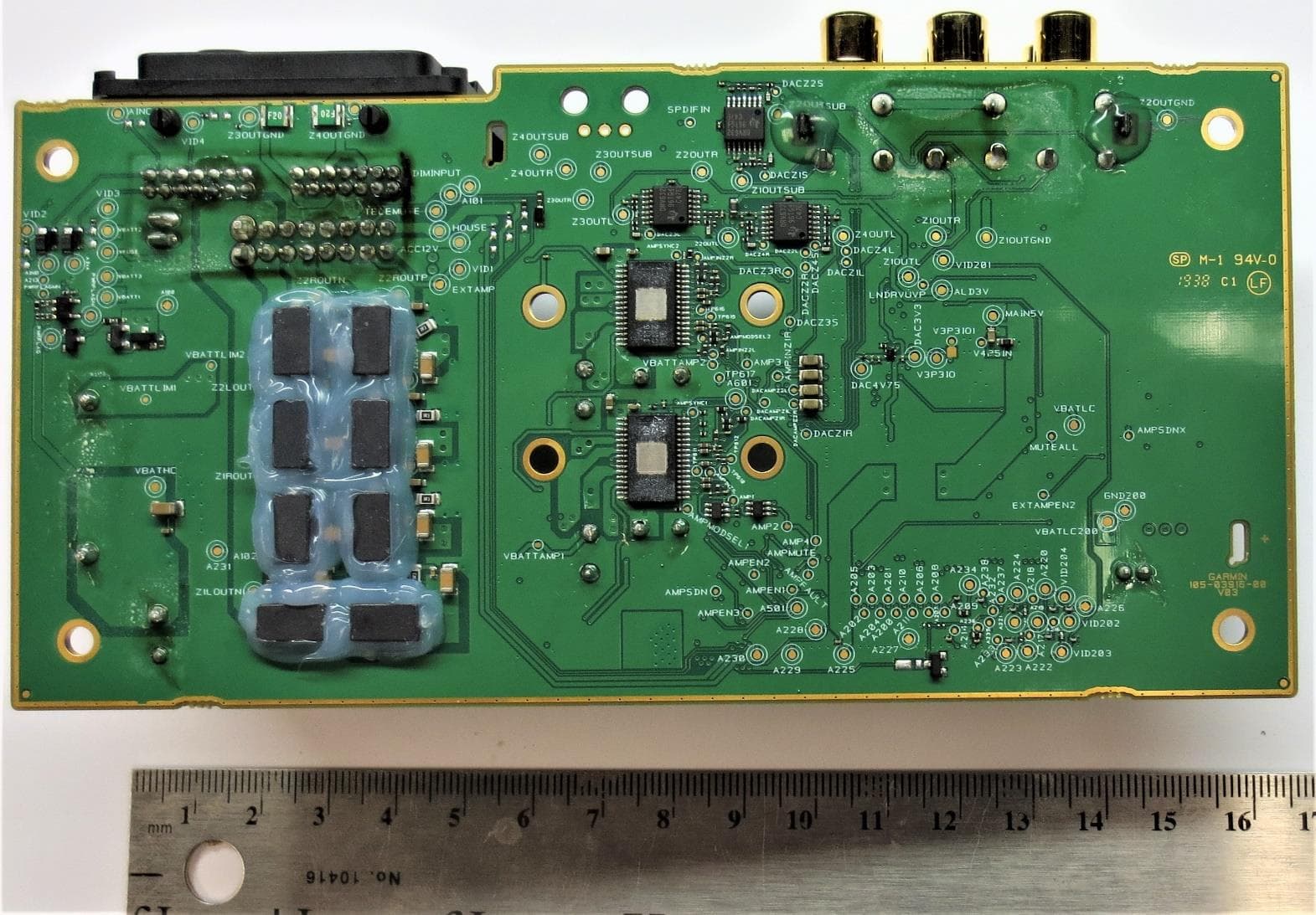
Click to zoom
Application Details
- Equipment Class
- DXX - Part 15 Low Power Communication Device Transmitter
- Date of Grant
- Apr 05, 2020
- Application Purpose
- Original Equipment
- Date of Application
- Apr 05, 2020
- Equipment Note
- Low Power Transmitter
- Frequency Range
- 2402.00000000 - 2480.00000000
- Company
- Garmin International Inc
- Country
- United States
Documents & Files
Document Text
Text extracted from the exhibit documents filed with the FCC. Open a document above to read the original.
Users Manual
VIEO ™ RV 51/52 INSTALLATION INSTRUCTIONS Important Safety Information WARNING See the Important Safety and Product Information guide in the product box for product warnings and other important information. NOTICE Failure to follow these cautions could result in damage to the vehicle or poor product performance. This device must be installed according to these instructions. Disconnect the vehicle's power supply before beginning to install this product. Before applying power to this product, make sure it has been correctly grounded according to the installation instructions. You must read all installation instructions before beginning the installation. If you experience difficulty during the installation, contact Garmin ® Product Support. Connector Identification Connector Identification (Vieo RV 51) ItemLabelDescriptionConnector Details ZONE 1 LINE OUT Line out connectors for zone 1 Left (white), right (red), and subwoofer (orange) RCA connectors ZONE 2 LINE OUT Line out connectors for zone 2 Left (white), right (red), and subwoofer (orange) RCA connectors NoneWiring harness connectors Connects to the included and optional wiring harnesses NoneAM/FM antenna connector Connects to either the vehicle's AM/FM antenna cable or an inline adapter attached to the vehicle's AM/FM antenna cable SiriusXMSiriusXM ® portConnects to a compatible SiriusXM Connect vehicle tuner and antenna (sold separately) USB (500 mA)Reserved for manufacturer use Compatible only with low- current (<500 mA) USB devices iPhone/iPodUSB (1 A)Interfaces with and charges supported smartphones and USB devices ItemLabelDescriptionConnector Details AUX 1 INPUT Auxiliary input 1Left (white) and right (red) RCA connectors CAMERA AUDIO INPUT/AUX 2 INPUT Input for camera audio or for auxiliary 2 Left (white) and right (red) RCA connectors NoneRJ-45Supports Ethernet connectivity CAN 1CAN BUS 1Connects to RV control systems using an adapter (sold separately) CAN 2CAN BUS 2Reserved for vehicle integration Connects to supported chassis CAN systems using an adapter cable to support steering wheel controls VIDEO INAnalog camera video input 4 RCA video connectors Connects to up to four vehicle cameras, including forward, left view, right view, and backup cameras MICMicrophone input3.5 mm mono microphone port Connects to the included microphone for hands-free calling Connector Identification (Vieo RV 52) ItemLabelDescriptionConnector Details ZONE 1 LINE OUT Line out connectors for zone 1 Left (white), right (red), and subwoofer (orange) RCA connectors ZONE 2 LINE OUT Line out connectors for zone 2 Left (white), right (red), and subwoofer (orange) RCA connectors NoneWiring harness connectors Connects to the included, optional wiring harnesses AM/FM/DABAM/FM/DAB connector (default source) Connects to a compatible antenna. Must be used for AM band (default) FM/DABConnector for alternate FM, FM and DAB, or DAB antenna Connects to a dedicated FM, FM and DAB, or DAB antenna if reception is not covered by the AM/FM/DAB antenna (requires menu reconfiguration) USB (500 mA)Reserved for manufacturer use Compatible only with low- current (<500 mA) USB devices iPhone/iPodUSB (1 A)Interfaces with and charges supported smartphones and USB devices AUX 1 INPUT Auxiliary input 1Left (white) and right (red) RCA connectors GUID-4F264AA7-30E5-4F0C-AD74-0C8DE09EE764 v1March 2020 ItemLabelDescriptionConnector Details CAMERA AUDIO INPUT/AUX 2 INPUT Input for camera audio or for auxiliary 2 Left (white) and right (red) RCA connectors NoneRJ-45Supports Ethernet connectivity CAN 1CAN BUS 1Connects to RV control systems using an adapter (sold separately) CAN 2CAN BUS 2Reserved for vehicle integration Connects to supported chassis CAN systems using an adapter cable to support steering wheel controls VIDEO INAnalog camera video input 4 RCA video connectors Connects to up to four vehicle cameras, including forward, left view, right view, and backup cameras MICMicrophone input3.5 mm mono microphone port Connects to the included microphone for hands-free calling Wiring Harnesses Power and Speaker Wiring Harness The power and speaker wiring harness contains the main power and speaker connections for the system. The harness connects directly to the stereo and to the vehicle wiring harness without modification. You can use this diagram to troubleshoot or to address non-default installation requirements. Wiring harnesses may vary based on installation requirements. Wire ColorFunctionNotes YellowPower (+)Connects to the positive terminal of a 12 Vdc power source capable of supplying 15 A. RedIgnitionConnects to a separately-switched, 12 Vdc connection, such as an ignition bus, to turn the stereo on. OrangeNoneReserved for future use. BlackGround (-)Connects to the negative terminal of a 12 Vdc power source capable of supplying 15 A. You should connect this wire before connecting the yellow wire. All accessories connected to the stereo must share a common ground location. BlueAmplifier onConnects to optional external amplifiers, enabling them to turn on when the stereo turns on. BrownNoneReserved for future use. PinkReverseConnects to an analog high signal, such as the reverse light, to activate the backup camera when the vehicle is placed in reverse. Red/blackHouseConnects to a 12 Vdc connection for the RV house power to turn the stereo on when the house power is turned on. WhiteSpeaker zone 1 left (+) White/blackSpeaker zone 1 left (-) Wire ColorFunctionNotes GraySpeaker zone 1 right (+) Gray/blackSpeaker zone 1 right (-) GreenSpeaker zone 2 left (+) Green/blackSpeaker zone 2 left (-) PurpleSpeaker zone 2 right (+) Purple/blackSpeaker zone 2 right (-) Line Out Wiring Harness The line out wiring harness (sold separately) outputs audio to an external amplifier for zones 3 and 4. LabelFunctionRCA connectors ZONE 3Outputs analog audio to an external amplifier for zone 3. Left (white), right (red), and sub (orange) ZONE 4Outputs analog audio to an external amplifier for zone 4. L…
Text truncated - open the document above for the full version.
Users Manual
Important Safety and Product Information2 Informations importantes sur le produit et la sécurité3 © 2020 Garmin Ltd. or its subsidiaries Printed in Taiwan April 2020 190-02657-94_0A Important Safety and Product Information WARNING Failure to heed the following warnings could result in an accident or collision resulting in death or serious injury. Distraction Warning This device is intended to enhance the situational awareness when used properly. If used improperly, you could become distracted by the display, which could lead to an accident causing serious personal injury or death. Only access the information displayed on the device with a glance. Always maintain awareness of your surroundings and do not stare at the display or become distracted by the display. Focusing on the display could prevent you from avoiding obstacles or hazards. Vehicle Installation Warnings • When installing the device in a vehicle, do not place the device where it obstructs the driver’s view of the road or interferes with vehicle operating controls, such as the steering wheel, foot pedals, or transmission levers. Do not place unsecured on the vehicle dashboard . Do not place the device in front of or above any airbag . Street Navigation Warnings If your Garmin ® device accepts street maps and suggests routes that follow roads, follow these guidelines to ensure safe on- road navigation. • Always use your best judgment, and operate the vehicle in a safe manner. Do not become distracted by the device while driving, and always be fully aware of all driving conditions. Minimize the amount of time spent viewing the device screen while driving. • Do not input destinations, change settings, or access any functions requiring prolonged use of the device controls while driving. Pull over in a safe and legal manner before attempting such operations. • When navigating, carefully compare information displayed on the device to all available navigation sources, including road signs, road closures, road conditions, traffic congestion, weather conditions, and other factors that may affect safety while driving. For safety, always resolve any discrepancies before continuing navigation, and defer to posted signs and conditions. • The device is designed to provide route suggestions. It is not a replacement for driver attentiveness and good judgement. Do not follow route suggestions if they suggest an illegal maneuver or would place the vehicle in an unsafe situation. Battery Warnings A lithium-ion battery can be used in this device. If these guidelines are not followed, batteries may experience a shortened life span or may present a risk of damage to the device, fire, chemical burn, electrolyte leak, and/or injury. • Do not disassemble, modify, remanufacture, puncture or damage the device or batteries. • Do not remove or attempt to remove the non-user-replaceable battery. • Do not expose the device or batteries to fire, explosion, or other hazard. Device Warnings • Do not immerse or expose the device or batteries to water or other liquids. • Do not leave the device exposed to a heat source or in a high-temperature location, such as in the sun in an unattended vehicle. To prevent the possibility of damage, remove the device from the vehicle or store it out of direct sunlight, such as in the glove box. • Do not operate the device outside of the following temperature range: from -20° to 55°C (from -4° to 131°F). • When storing the device for an extended time period, store within the following temperature range: from 0° to 25°C (from 32° to 77°F). • Do not use a power cable, data cable and/or power adapter that is not approved or supplied by Garmin. Magnet Warning Both the device and its mount may contain magnets. Under certain circumstances, magnets may cause interference with some internal medical devices, including pacemakers and insulin pumps. Devices and mounts that contain magnets should be kept away from such medical devices. Hearing Damage Warning Listening to the stereo at high volume can cause damage to your hearing. You can permanently damage your ears and lose hearing if you listen to the device, earbuds, or headphones at high volume. If you experience ringing in your ears or muffled speech, stop listening and have your hearing checked. NOTICE Failure to heed the following notice could result in personal or property damage, or negatively impact the device functionality. Windshield Mounting Legal Restrictions Before using the device on your windshield, check the state and local laws and ordinances where you drive. Some state laws prohibit or restrict the placement of objects on the windshield of a motor vehicle. IT IS THE USER'S RESPONSIBILITY TO MOUNT THE DEVICE IN COMPLIANCE WITH ALL APPLICABLE LAWS AND ORDINANCES. Always mount your Garmin device in a location that does not obstruct the driver's view of the road. Garmin does not assume any responsibility for any fines, penalties, or damages that may be incurred as a result of any state or local law or ordinance relating to the use of your Garmin device. Battery Notices • Contact your local waste disposal department to dispose of the device/batteries in accordance with applicable local laws and regulations. Speed Limit Notice The speed limit feature is for information only and does not replace the driver’s responsibility to abide by all posted speed limit signs and to use safe driving judgment at all times. Garmin will not be responsible for any traffic fines or citations that you may receive for failing to follow all applicable traffic laws and signs. Magnet Notice Both the device and its mount may contain magnets. Under certain circumstances, magnets may cause damage to some electronic devices, including hard drives in laptop computers. Use caution when devices and mounts that contain magnets are near electronic devices. GPS Notice The navigation device may experience degraded performance if you use it in proximity to any device that uses a terrestrial broadband network op…
Text truncated - open the document above for the full version.
Cover Letter(s)
Page 1 of 2 March 20, 2020 Timco Engineering Inc. 849 NW State Road 45 Newberry, FL 32669 Applicant: Garmin International, Inc. 1200 East 151st Street Olathe, KS 66062 Re: Confidentiality for submittal information regarding FCC ID: IPH-03915 Product: Transmitter operated under 47CFR Section 15C Dear Sirs: Garmin International, Inc. requests that the material in the Block Diagram, Operational Description, Schematics, and Tune up Procedure be withheld from public disclosure pursuant to Sections 0.457 and 0.459 of the Commission’s Rules following grant of the application. In support of this request, Garmin International, Inc. submits the following information. CONFIDENTIAL FILES A03915 Conf BlkDia.pdf A03915 Conf OpDes.pdf A03915 Conf Schem.pdf A03915 Conf TunPro.pdf 1. Identification of the specific information for which confidential treatment is sought: The materials set forth in the Block Diagram, Operational Description, Schematics, and Tune up Procedure which are segregated, from the non-confidential exhibits of the application, are those for which confidentiality is sought. 2. Identification of the Commission proceeding in which the information was submitted or a description of the circumstances giving rise to the submission: The proceeding is that involving the application for equipment authorization (certification) under FCC ID: IPH-03915 3. Explanation of the degree to which the information is commercial or financial, or contains a trade secret or is privileged: This material includes a detailed Block Diagram, Operational Description, Schematics, and Tune up Procedure. As such, this material is treated as highly confidential business information. ROGERS LABS, INC. 4405 West 259 th Terrace Louisburg, KS 66053 913 837-3214 Page 2 of 2 4. Explanation of the degree to which the information concerns a service that is subject to competition: The material for which confidentiality is sought is employed in the design and manufacture of this transmitting equipment that is offered on a highly competitive basis. Customers for this equipment have a variety of competing sources. 5. Explanation of how disclosure of the information could result in substantial competitive harm: Disclosure would, in effect, give away the fruits of the labors of Garmin International, Inc.’s engineering personnel, who have designed the equipment and the manufacturing process. Disclosure would also offer competitors additional unwarranted insight into the state of the product development, thereby allowing competitors an advantage, not available to Garmin International, Inc. 6. Identification of any measures taken by the submitting party to prevent unauthorized disclosure: The information for which confidential treatment is sought is kept confidential by Garmin International, Inc. and not made available to third parties except pursuant to non-disclosure agreements. 7. Identification of whether the information is available to the public and the extent of any previous disclosure of the information to third parties: To the knowledge of those preparing this application, the information has not been disclosed publicly heretofore. While the general theory of operation of this equipment has been the subject of numerous disclosures in industry the protection sought is narrowly drawn as provided in regulations. 8. Justification of the period during which the submitting party asserts that the material should not be available for public disclosure: This material should not be disclosed for at least 25 years. While improvements in design are made relatively frequently, disclosure of the design information would lead to insights into both design and manufacturing techniques that could have an adverse competitive effect for many years to come. As such, it is important that the design not be made available to unauthorized persons who might attempt to use knowledge of the design to compromise the applications for which the equipment will be employed. Should you require any further information, please contact the undersigned. Thank you for your consideration in this matter. Sincerely, Scot Rogers
Cover Letter(s)
March 20, 2020 Timco Engineering Inc. 849 NW State Road 45 Newberry, FL 32669 Applicant: Garmin International, Inc. Equipment: FCC ID: IPH-03915 1200 East 151st Street CORES number: 0005088588 Olathe, KS 66062 Re: Grant Deferral Date April 6, 2020 To Whom It May Concern: Please be advised Garmin International, Inc. requests the associated application be processed and defer issuance of the Grant of Authorization until April 6, 2020. Should you require any further information, please contact the undersigned. Thank you for your consideration in this matter. Sincerely, Scot Rogers Rogers Labs, Inc. Enclosures ROGERS LABS, INC. 4405 West 259 th Terrace Louisburg, KS 66053 Phone / Fax (913) 837-3214
Cover Letter(s)
March 27, 2020 Timco Engineering Inc. 849 NW State Road 45 Newberry, FL 32669 Applicant: Garmin International, Inc. 1200 East 151st Street Olathe, KS 66062 Re: Short-term Confidentiality request for submittal information regarding FCC ID: IPH-03915 FCC Rules: Parts 2 and 15C Dear Sirs: Garmin International, Inc. requests that the following information be withheld from public disclosure pursuant to CFR47 paragraphs 0.457 and 0.459, and KDB 726920 until 35 days after the Grant of Equipment Authorization. Disclosure of information would offer competitors additional unwarranted insight into the state of the product development. Short-term confidential files File A03915 Short Term Conf ExtPho.pdf A03915 Short Term Conf IntPho.pdf A03915 Short Term Conf TSup.pdf A03915 Short Term Conf UserMan.pdf A03915 Short Term Conf UserMan 1.pdf Should you require any further information, please contact the undersigned. Thank you for your consideration in this matter. Sincerely, Scot Rogers ROGERS LABS, INC. 4405 West 259 th Terrace Louisburg, KS 66053 +1 913 837-3214
Cover Letter(s)
March 20, 2020 Timco Engineering Inc. 849 NW State Road 45 Newberry, FL 32669 Applicant: Garmin International, Inc. 1200 East 151st Street Olathe, KS 66062 CORES number: 0005088588 Equipment: FCC ID: IPH-03915 FCC Rules: Parts 2, 15C To Whom It May Concern: The form 731 and application have been electronically submitted and any attachments will be uploaded to your web site for use in obtaining a grant of certification. Confidentiality is requested as outlined below. Permanent Garmin International, Inc. requests that the material in the Block Diagram, Operational Description, Schematics, and Tune up Procedure be withheld from public disclosure pursuant to Sections 0.457 and 0.459 of the Commission’s Rules following grant of the application. A statement of confidentiality will be attached with the application at the time of submittal. CONFIDENTIAL FILES A03915 Conf BlkDia.pdf A03915 Conf OpDes.pdf A03915 Conf Schem.pdf A03915 Conf TunPro.pdf Should you require any further information, please contact the undersigned. Thank you for your consideration in this matter. Sincerely, Scot Rogers Rogers Labs, Inc. Enclosures ROGERS LABS, INC. 4405 West 259 th Terrace Louisburg, KS 66053 Phone / Fax (913) 837-3214
ID Label/Location Info
Rogers Labs, Inc. Garmin International, Inc. SN’s: 3303700951, 3303700953 4405 West 259 th Terrace Model: A03915 FCC ID: IPH-03915 Louisburg, KS 66053 Test: 191105 IC: 1792A-03915 Phone/Fax: (913) 837-3214 Test to: 47 CFR 15C, RSS-210, RSS-247 Date: March 20, 2020 Revision 1 File: A03915 FCC LabelSmpl Page 1 of 1 A03915 FCC Label & Placement Top of Unit Label Location
Internal Photos
Rogers Labs, Inc. Garmin International, Inc. SN’s: 3303700951, 3303700953 4405 West 259 th Terrace Model: A03915 FCC ID: IPH-03915 Louisburg, KS 66053 Test: 191105 IC: 1792A-03915 Phone/Fax: (913) 837-3214 Test to: CFR47 15C, RSS-210, RSS-247 Date: March 20, 2020 Revision 1 File: A03915 Short Term Conf IntPho Page 1 of 8 012-03915-00 Linux Board Rogers Labs, Inc. Garmin International, Inc. SN’s: 3303700951, 3303700953 4405 West 259 th Terrace Model: A03915 FCC ID: IPH-03915 Louisburg, KS 66053 Test: 191105 IC: 1792A-03915 Phone/Fax: (913) 837-3214 Test to: CFR47 15C, RSS-210, RSS-247 Date: March 20, 2020 Revision 1 File: A03915 Short Term Conf IntPho Page 2 of 8 012-03915-00 Linux Board with shield installed Rogers Labs, Inc. Garmin International, Inc. SN’s: 3303700951, 3303700953 4405 West 259 th Terrace Model: A03915 FCC ID: IPH-03915 Louisburg, KS 66053 Test: 191105 IC: 1792A-03915 Phone/Fax: (913) 837-3214 Test to: CFR47 15C, RSS-210, RSS-247 Date: March 20, 2020 Revision 1 File: A03915 Short Term Conf IntPho Page 3 of 8 012-03916-00 Amplifier Board Rogers Labs, Inc. Garmin International, Inc. SN’s: 3303700951, 3303700953 4405 West 259 th Terrace Model: A03915 FCC ID: IPH-03915 Louisburg, KS 66053 Test: 191105 IC: 1792A-03915 Phone/Fax: (913) 837-3214 Test to: CFR47 15C, RSS-210, RSS-247 Date: March 20, 2020 Revision 1 File: A03915 Short Term Conf IntPho Page 4 of 8 012-03917-00 Mount Front Board Rogers Labs, Inc. Garmin International, Inc. SN’s: 3303700951, 3303700953 4405 West 259 th Terrace Model: A03915 FCC ID: IPH-03915 Louisburg, KS 66053 Test: 191105 IC: 1792A-03915 Phone/Fax: (913) 837-3214 Test to: CFR47 15C, RSS-210, RSS-247 Date: March 20, 2020 Revision 1 File: A03915 Short Term Conf IntPho Page 5 of 8 012-03918-00 Mount Adapter Board Rogers Labs, Inc. Garmin International, Inc. SN’s: 3303700951, 3303700953 4405 West 259 th Terrace Model: A03915 FCC ID: IPH-03915 Louisburg, KS 66053 Test: 191105 IC: 1792A-03915 Phone/Fax: (913) 837-3214 Test to: CFR47 15C, RSS-210, RSS-247 Date: March 20, 2020 Revision 1 File: A03915 Short Term Conf IntPho Page 6 of 8 105-03969-00 Touch Button FPC (two places) Rogers Labs, Inc. Garmin International, Inc. SN’s: 3303700951, 3303700953 4405 West 259 th Terrace Model: A03915 FCC ID: IPH-03915 Louisburg, KS 66053 Test: 191105 IC: 1792A-03915 Phone/Fax: (913) 837-3214 Test to: CFR47 15C, RSS-210, RSS-247 Date: March 20, 2020 Revision 1 File: A03915 Short Term Conf IntPho Page 7 of 8 012-03915-00 Linux Board (Transmitters/RF Connectors Annotated) Rogers Labs, Inc. Garmin International, Inc. SN’s: 3303700951, 3303700953 4405 West 259 th Terrace Model: A03915 FCC ID: IPH-03915 Louisburg, KS 66053 Test: 191105 IC: 1792A-03915 Phone/Fax: (913) 837-3214 Test to: CFR47 15C, RSS-210, RSS-247 Date: March 20, 2020 Revision 1 File: A03915 Short Term Conf IntPho Page 8 of 8 012-03917-00 Mount Front Board (Antennas/RF Connectors Annotated)
RF Exposure Info
Rogers Labs, Inc. Garmin International, Inc. SN’s: 3303700951, 3303700953 4405 West 259 th Terrace Model: A03915 FCC ID: IPH-03915 Louisburg, KS 66053 Test: 191105 IC: 1792A-03915 Phone/Fax: (913) 837-3214 Test to: CFR47 15C, RSS-210, RSS-247 Date: March 20, 2020 Revision 1 File: A03915 RF Exemption Page 1 of 2 Transmitter #1 Model: A03915Test Number:191105 MPE CalculatorRF Exposure uses EIRP for calculation. EIRP is based on TX power added to the antenna gain in dBi. dBi = dB gain compared to an isotropic radiator. S = power density in mW/cm^2 Transmitter Output power (dBm)0.70 Transmitter Output power (mW)1.17 Output Power for % duty Cycle operation (Watts)1000.0012Antenna Gain (dBi)1.9 Output Power for 100% duty Cycle operation (Watts)0.00Antenna Gain (Numeric)1.55 Tx Frequency (MHz)2442Calcualtion power (Watts)0.00dBd + 2.17 = dBidBi to dBd2.2 Antenna Gain (dBd)-0.27 Cable Loss (dB)0.0Adjusted Power (dBm)0.70Antenna minus cable (dBi)1.90 Calculated ERP (mw)1.104EIRP = Po(dBM) + Gain (dB) Calculated EIRP (mw)1.820Radiated (EIRP) dBm2.600 ERP = EIRP - 2.17 dB Radiated (ERP) dBm0.430 Occupational Limit 5 mW/cm 2 Frequency (MHz) Occupational Limit (mW/cm 2 )Public Limit (mW/cm 2 ) 50 W/m 2 30-30010.2 General Public Limit300-1,500f/300f/1500 1 mW/cm 2 1,500-10,00051 10 W/m 2 Occupational Limit 0.6455ƒ 0.5 W/m 2 39.7 W/m 2 Frequency (MHz) Occupational Limit (W/m 2 )Public Limit (W/m 2 ) General Public Limit100-6,000 0.6455ƒ 0.5 0.02619ƒ 0.6834 W/m 2 6,000-15,00050 5.4 W/m 2 48-3001.291 300-6,000 0.02619ƒ 0.6834 6,000-15,0005010 f = Transmit Frequecny (MHz) f (MHz) =2442MHz P T = Power Input to Antenna (mW) P T (mW) = 1.1749 mW Duty cycle (percentage of operation) % =100% P A = Adjusted Power due to Duty cycle or Cable Loss (mW) P A (mW) = 1.17 mW G N = Numeric Gain of the Antenna GN (numeric) =2.17numeric S 20 = Power Density of device at 20cm (mW/m 2 ) S 20 =(P A G N )/(4πR 20 ) 2 S 20 (mW/m 2 ) = 0.00 mW/m 2 S 20 = Power Density of device at 20cm (W/m 2 ) S 20 =(P A G N )/(4πR 20 ) 2 S 20 (W/m 2 ) = 0.01 W/m 2 S L = Power Density Limit (W/m 2 ) S L (W/m 2 )= 5.412 W/m 2 R C = Minimum distance to the Radiating Element for Compliance (cm) R C =√(P A G N /4πS L )R C (cm) =0.6cm S C = Power Density of the device at the Compliance Distance R C (W/m 2 ) S C =(P A G N )/(4πR C ) 2 S C (W/m 2 ) = 5.41 W/m 2 R 20 = 20cm R20=20cm For Complaince with Canada General Population Limits, User Manual must indicate a minimum seperation distance of 0.6cm Or in Meters for Complaince with Canada General Population Limits, a minimum seperation distance of 0.01Meters Summary: Standalone MPE Calculations and Summary Tx#, Band (MHz)Tx Duty Cycle (%)Tx Frequeny (MHz)Power Total (mW)Antenna Gain (dBi) S L (W/m 2 )S 20 (W/m 2 ) R C (cm) S C (W/m 2 ) Tx1, 2402-2480100244211.95.4120.010.65.41 Band (MHZ)Tx Duty Cycle (%)Tx Frequeny (MHz)Power Total (mW)Antenna Gain (dBi)SL (W/m2)S20 (W/m2)RC (cm)SC (W/m2) Tx2, 2402-248010024403.632.175.4090.021.15.41 Transmitter 1Transmitter 2 Tx Frequeny (MHz)24422440 S 20 (W/m 2 ) 0.010.02 S L (W/m 2 ) 5.4125.409 Power Ratio (S L / S 20 )0.0010.003 Sum of Power Ratios at 20cm (Tx1 + Tx2)0.004 Requirement = Σ of MPE Ratio ≤ 1 FCC radio frequency radiation exposure limits per 1.1310 IC radio frequency radiation exposure limits per RSS-102 Simlutaneous MPE Calculation EIRP Power density (S) mW/cm 2 =------- 4 pr^2 r (cm) EIRP (mW) Rogers Labs, Inc. Garmin International, Inc. SN’s: 3303700951, 3303700953 4405 West 259 th Terrace Model: A03915 FCC ID: IPH-03915 Louisburg, KS 66053 Test: 191105 IC: 1792A-03915 Phone/Fax: (913) 837-3214 Test to: CFR47 15C, RSS-210, RSS-247 Date: March 20, 2020 Revision 1 File: A03915 RF Exemption Page 2 of 2 Transmitter #2 Model: A03915 Test Number: 191105 MPE Calculator RF Exposure uses EIRP for calculation. EIRP is based on TX power added to the antenna gain in dBi. dBi = dB gain compared to an isotropic radiator. S = power density in mW/cm^2 Transmitter Output power (dBm) 5.60 Transmitter Output power (mW) 3.63 Output Power for % duty Cycle operation (Watts) 100 0.0036 Antenna Gain (dBi) 1.3 Output Power for 100% duty Cycle operation (Watts) 0.00 Antenna Gain (Numeric) 1.35 Tx Frequency (MHz) 2440 Calcualtion power (Watts) 0.00 dBd + 2.17 = dBi dBi to dBd 2.2 Antenna Gain (dBd) -0.87 Cable Loss (dB) 0.0 Adjusted Power (dBm) 5.60 Antenna minus cable (dBi) 1.30 Calculated ERP (mw) 2.972 EIRP = Po(dBM) + Gain (dB) Calculated EIRP (mw) 4.898 Radiated (EIRP) dBm 6.900 ERP = EIRP - 2.17 dB Radiated (ERP) dBm 4.730 Occupational Limit 5 mW/cm 2 Frequency (MHz) Occupational Limit (mW/cm 2 ) Public Limit (mW/cm 2 ) 50 W/m 2 30-300 1 0.2 General Public Limit 300-1,500 f/300 f/1500 1 mW/cm 2 1,500-10,000 5 1 10 W/m 2 Occupational Limit 0.6455ƒ 0.5 W/m 2 39.7 W/m 2 Frequency (MHz) Occupational Limit (W/m 2 ) Public Limit (W/m 2 ) General Public Limit 100-6,000 0.6455ƒ 0.5 0.02619ƒ 0.6834 W/m 2 6,000-15,000 50 5.4 W/m 2 48-300 1.291 300-6,000 0.02619ƒ 0.6834 6,000-15,000 50 10 f = Transmit Frequecny (MHz) f (MHz) = 2440 MHz P T = Power Input to Antenna (mW) P T (mW) = 3.6308 mW Duty cycle (percentage of operation) % = 100 % P A = Adjusted Power due to Duty cycle or Cable Loss (mW) P A (mW) = 3.63 mW G N = Numeric Gain of the Antenna GN (numeric) = 2.17 numeric S 20 = Power Density of device at 20cm (mW/m 2 ) S 20 =(P A G N )/(4πR 20 ) 2 S 20 (mW/m 2 ) = 0.00 mW/m 2 S 20 = Power Density of device at 20cm (W/m 2 ) S 20 =(P A G N )/(4πR 20 ) 2 S 20 (W/m 2 ) = 0.02 W/m 2 S L = Power Density Limit (W/m 2 ) S L (W/m 2 )= 5.409 W/m 2 R C = Minimum distance to the Radiating Element for Compliance (cm) R C =√ (P A G N /4π S L ) R C (cm) = 1.1 cm S C = Power Density of the device at the Compliance Distance R C (W/m 2 ) S C =(P A G N )/(4πR C ) 2 S C (W/m 2 ) = 5.41 W/m 2 R 20 = 20cm R20= 20 cm For Complaince with Canada General Population Limits, User Manual must indicate a minimum seperation distance of 1.1 cm Or in Meters for Complaince with Canada General Population Limits…
Text truncated - open the document above for the full version.
Test Report
Testing NVLAP Lab Code 200087-0 Rogers Labs, Inc. Garmin International, Inc. SN’s: 3303700951, 3303700953 4405 West 259 th Terrace Model: A03915 FCC ID: IPH-03915 Louisburg, KS 66053 Test: 191105 IC: 1792A-03915 Phone/Fax: (913) 837-3214 Test to: CFR47 15.249, RSS-210, RSS-Gen Date: January 29, 2020 Revision 1 File: A03915 DXX TstRpt 191105 Page 1 of 37 Application For Grant of Certification 47 CFR, PART 15C - Intentional Radiators 47 CFR Paragraph 15.249 and Industry Canada RSS-GEN Issue 5 and RSS-210 Issue 10 Model: A03915 2402-2480 MHz (DXX) Low Power Digital Transmitter FCC ID: IPH-03915 IC: 1792A-03915 Garmin International, Inc. 1200 East 151st Street Olathe, KS 66062 FCC Designation: US5305 ISED Registration: 3041A-1 Test Report Number: 191105 Test Date: November 05, 2019 Authorized Signatory: Scot D. Rogers This report shall not be reproduced except in full, without the written approval of the laboratory. This report must not be used by the client to claim product certification, approval, or endorsement by NVLAP, NIST, or any agency of the U.S. Government. ROGERS LABS, INC. 4405 West 259 th Terrace Louisburg, KS 66053 Phone / Fax (913) 837-3214 Testing NVLAP Lab Code 200087-0 Rogers Labs, Inc. Garmin International, Inc. SN’s: 3303700951, 3303700953 4405 West 259 th Terrace Model: A03915 FCC ID: IPH-03915 Louisburg, KS 66053 Test: 191105 IC: 1792A-03915 Phone/Fax: (913) 837-3214 Test to: CFR47 15.249, RSS-210, RSS-Gen Date: January 29, 2020 Revision 1 File: A03915 DXX TstRpt 191105 Page 2 of 37 Tabl e of Cont ents Table of Contents TABLE OF CONTENTS ................…
Text truncated - open the document above for the full version.
Contact Information
Applicant
Ben Karsak(Manager, Compliance Engineering)
Test Firm
Rogers Labs, Inc.Scot Rogers
Technical Specifications
| # | Rule Parts | Frequency Range | Power Output |
|---|---|---|---|
| 1 | 15C | 2.40 GHz - 2.48 GHz | - |
Other Applications from Garmin International Inc
IPH-05126
Sep 09, 2026Portable Digital Transceiver
Equipment Class
NII - Unlicensed National Information Infrastructure TXIPH-A5126
Sep 09, 2026Portable Digital Transceiver
Equipment Class
NII - Unlicensed National Information Infrastructure TXIPH-04812
Sep 01, 2026Mobile Digital Transceiver
Equipment Class
DTS - Digital Transmission SystemIPH-A04825
Sep 01, 2026Marine Stereo
Equipment Class
DSS - Part 15 Spread Spectrum TransmitterIPH-B04825
Sep 01, 2026Marine Stereo
Equipment Class
DSS - Part 15 Spread Spectrum Transmitter