IPH-03941Radar
Garmin International Inc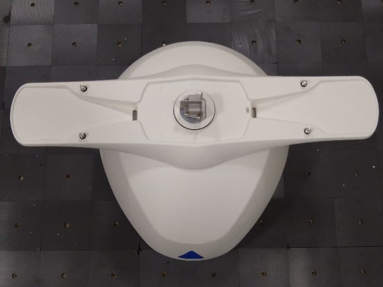
Click to zoom
Application Details
- Equipment Class
- MRD - Marine Radar
- Date of Grant
- Aug 03, 2020
- Application Purpose
- Original Equipment
- Date of Application
- Aug 03, 2020
- Equipment Note
- Radar
- Frequency Range
- 9300.00000000 - 9500.00000000
- Company
- Garmin International Inc
- Country
- United States
Documents & Files
Document Text
Text extracted from the exhibit documents filed with the FCC. Open a document above to read the original.
Users Manual
GMR FANTOM ™ OPEN ARRAY SERIES INSTALLATION INSTRUCTIONS Important Safety Information WARNING See the Important Safety and Product Information guide in the product box for product warnings and other important information. The radar transmits electromagnetic energy. Ensure that the radar is installed according to the recommendations in these instructions and that all personnel are clear of the path of the radar beam before transmitting. When properly installed and operated, the use of this radar conforms to the requirements of ANSI/IEEE C95.1-1992 Standard for Safety Levels with Respect to Human Exposure to Radio Frequency Electromagnetic Fields. When the radar is transmitting, do not look directly at the antenna at close range; eyes are the most sensitive part of the body to electromagnetic energy. When connecting the power cable, do not remove the in-line fuse holder. To prevent the possibility of injury or product damage caused by fire or overheating, the appropriate fuse must be in place as indicated in the product specifications. In addition, connecting the power cable without the appropriate fuse in place voids the product warranty. CAUTION This device should be used only as a navigational aid. Do not attempt to use the device for any purpose requiring precise measurement of direction, distance, location, or topography. Always wear safety goggles, ear protection, and a dust mask when drilling, cutting, or sanding. Opening the device may result in personal injury and/or damage to the device. This device contains no user-serviceable parts, and should be opened only by a Garmin ® authorized service technician. Any damage resulting from opening the unit by anyone other than a Garmin authorized service technician will not be covered by the Garmin warranty. NOTICE When drilling or cutting, always check what is on the opposite side of the surface. Tools Needed • #2 Phillips screwdriver • 5 mm hex wrench • Drill • 15 mm ( 19 / 32 in.) drill bit • 32 mm (1 1 / 4 in.) drill bit (optional) • 17 mm ( 21 / 32 in.) wrench and torque wrench • 3.31 mm² (12 AWG) copper wire to ground the radar housing and voltage converter, if applicable (the length depends on the distance from the radar to ground) • Marine sealant Mounting Considerations When selecting a mounting location, observe these considerations. • It is highly recommended that the device is mounted out of range of people, with the vertical beam width above head height. To avoid exposure to harmful radio frequency (RF) levels, the device should not be mounted closer to people than the maximum safe distance value listed in the product specifications. • The device should be mounted high above the ship’s keel line with minimal blockage of the radar beam. Obstructions may cause blind and shadow sectors or generate false echoes. The higher the installation position, the farther the radar can detect targets. • The device should be mounted on a flat surface or a platform that is parallel to the vessel's water line and is sturdy enough to support the device's weight. The weight for each model and antenna is listed in the product specifications. • The device must be mounted in a location where it can be connected to power, water ground, and the Garmin Marine Network (Wiring and Connection Considerations, page 2). • The radar beam spreads vertically 11.5° above and 11.5° below the radar's radiating element. On vessels with higher bow angles at cruise speed, the installation angle can be lowered to point the beam slightly downward to the waterline while at rest. Shims can be used if necessary. • The device should be mounted away from heat sources, such as smoke stacks and lights. • The device should be mounted at a different level than horizontal spreaders and mast crosstrees. • To avoid interference with a magnetic compass, the device should not be mounted closer to a compass than the compass-safe distance value listed in the product specifications. • Other electronics and cables should be mounted more than 2 m (6.5 ft.) from the radar beam path. • GPS antennas should be either above or below the radar beam path. • The device should be mounted at least 1 m (40 in.) from any transmitting equipment. • The device should be mounted at least 1 m (40 in.) away from cables carrying radio signals such as VHF radios, cables, and antennas. • The device should be mounted at least 2 m (6.5 ft.) away from Single Side Band (SSB) radios. Installation Procedures Preparing the Radar Mounting Surface Before you can mount the radar, you must choose a suitable mounting location (Mounting Considerations, page 1). 1 Secure the included mounting template to the surface at the mounting location, along the bow-stern axis, as indicated on the template. 2 Drill the mounting holes using a 15 mm ( 19 / 32 in.) drill bit. 3 If you need to run the power and network cables through the mounting surface, select a location along the center channel indicated on the template, drill a pass-through hole for the cables using a 32 mm (1 1 / 4 in.) drill bit, and route the cables through the surface (optional) (Wiring and Connection Considerations, page 2). 4 Remove the mounting template from the surface. Mounting the Radar Before you can mount the radar, you must select a mounting location (Mounting Considerations, page 1) and prepare the mounting surface (Preparing the Radar Mounting Surface, page 1). Printed in Taiwan April 2020 RC DRAFT 1 Place the radar onto the mounting surface, aligning the holes on the base of the radar with the holes you drilled when preparing the mounting surface. 2 Apply the included Petrolatum Primer to the threads of the four threaded rods. 3 Insert the threaded rods through the mounting surface and into the radar base, and tighten them using a 5 mm hex wrench. To avoid damaging the pedestal, you should stop tightening the threaded rods when they no longer turn easily. 4 From under the mounting surface, place the included plastic shoulder washers over the threaded…
Text truncated - open the document above for the full version.
Users Manual
Important Safety and Product Information2 Informations importantes sur le produit et la sécurité3 guida Informazioni importanti sulla sicurezza e sul prodotto 4 Wichtige Sicherheits- und Produktinformationen5 Información importante sobre el producto y tu seguridad 6 Informações importantes sobre segurança e sobre o produto7 Belangrijke veiligheids- en productinformatie8 Vigtige produkt- og sikkerhedinformationer9 Tärkeitä turvallisuus- ja tuotetietoja10 Viktig sikkerhets- og produktinformasjon11 Guiden Viktig säkerhets- och produktinformation12 Važne informacije o proizvodu i sigurnosti13 重要安全和产品信息14 © 2016–2017 Garmin Ltd. or its subsidiaries May 2017 190-00720-87_0B IMPORTANT SAFETY AND PRODUCT INFORMATION WARNING Failure to heed the following warnings could result in an accident or collision resulting in death or serious injury. Marine Operation Warnings •You are responsible for the safe and prudent operation of your vessel. This device does not relieve you from the responsibility of safely operating your vessel. Avoid navigational hazards and never leave the helm unattended. •Always be prepared to promptly regain control of the vessel. Use caution near hazards in the water, such as docks, pilings and other vessels. NOTICE Failure to heed the following notice could result in personal or property damage, or negatively impact the device functionality. GPS Notice The navigation device may experience degraded performance if you use it in proximity to any device that uses a terrestrial broadband network operating close to the frequencies used by any Global Navigation Satellite System (GNSS), such as the Global Positioning Service (GPS). Use of such devices may impair reception of GNSS signals. Product Environmental Programs Information about the Garmin ® product recycling program and WEEE, RoHS, REACH, and other compliance programs can be found at www.garmin.com/aboutGarmin/environment. Declaration of Conformity Hereby, Garmin declares that this product is in compliance with the Directive 2014/53/EU. The full text of the EU declaration of conformity is available at the following internet address: www.garmin.com /compliance. Innovation, Science and Economic Development Canada Compliance This device complies with Innovation, Science and Economic Development Canada license-exempt RSS standard(s). Operation is subject to the following two conditions: (1) this device may not cause interference, and (2) this device must accept any interference, including interference that may cause undesired operation of the device. Radio Frequency Radiation Exposure This device is a mobile transmitter and receiver that uses an internal antenna to send and receive low levels of radio frequency (RF) energy for data communications. The device emits RF energy below the published limits when operating in its maximum output power mode and when used with Garmin authorized accessories. To comply with RF exposure compliance requirements, the device should be installed and used with the separation distance as described in the printed manual. The device should not be used in other configurations. This device must not be co-located or operated in conjunction with any other transmitter or antenna. FCC Compliance This device complies with part 15 of the FCC Rules. Operation is subject to the following two conditions: (1) this device may not cause harmful interference, and (2) this device must accept any interference received, including interference that may cause undesired operation. This equipment has been tested and found to comply with the limits for a Class B digital device, pursuant to part 15 of the FCC rules. These limits are designed to provide reasonable protection against harmful interference in a residential installation. This equipment generates, uses, and can radiate radio frequency energy and may cause harmful interference to radio communications if not installed and used in accordance with the instructions. However, there is no guarantee that interference will not occur in a particular installation. If this equipment does cause harmful interference to radio or television reception, which can be determined by turning the equipment off and on, the user is encouraged to try to correct the interference by one of the following measures: •Reorient or relocate the receiving antenna. •Increase the separation between the equipment and the receiver. •Connect the equipment into an outlet that is on a different circuit from the GPS device. •Consult the dealer or an experienced radio/TV technician for help. This product does not contain any user-serviceable parts. Repairs should only be made by an authorized Garmin service center. Unauthorized repairs or modifications could result in permanent damage to the equipment, and void your warranty and your authority to operate this device under Part 15 regulations. Software License Agreement BY USING THE DEVICE, YOU AGREE TO BE BOUND BY THE TERMS AND CONDITIONS OF THE FOLLOWING SOFTWARE LICENSE AGREEMENT. PLEASE READ THIS AGREEMENT CAREFULLY. Garmin Ltd. and its subsidiaries (“Garmin”) grant you a limited license to use the software embedded in this device (the “Software”) in binary executable form in the normal operation of the product. Title, ownership rights, and intellectual property rights in and to the Software remain in Garmin and/or its third-party providers. You acknowledge that the Software is the property of Garmin and/or its third-party providers and is protected under the United States of America copyright laws and international copyright treaties. You further acknowledge that the structure, organization, and code of the Software, for which source code is not provided, are valuable trade secrets of Garmin and/or its third-party providers and that the Software in source code form remains a valuable trade secret of Garmin and/or its third-party providers. You agree not to decompile, disassemble, modify, reverse assemble, reverse engineer, or reduce to human readable fo…
Text truncated - open the document above for the full version.
Users Manual
GMR FANTOM ™ 50/120 SERIES INSTALLATION INSTRUCTIONS Important Safety Information WARNING See the Important Safety and Product Information guide in the product box for product warnings and other important information. The radar transmits electromagnetic energy. Ensure that the radar is installed according to the recommendations in these instructions and that all personnel are clear of the path of the radar beam before transmitting. When properly installed and operated, the use of this radar conforms to the requirements of ANSI/IEEE C95.1-1992 Standard for Safety Levels with Respect to Human Exposure to Radio Frequency Electromagnetic Fields. When the radar is transmitting, do not look directly at the antenna at close range; eyes are the most sensitive part of the body to electromagnetic energy. When connecting the power cable, do not remove the in-line fuse holder. To prevent the possibility of injury or product damage caused by fire or overheating, the appropriate fuse must be in place as indicated in the product specifications. In addition, connecting the power cable without the appropriate fuse in place voids the product warranty. CAUTION This device should be used only as a navigational aid. Do not attempt to use the device for any purpose requiring precise measurement of direction, distance, location, or topography. Always wear safety goggles, ear protection, and a dust mask when drilling, cutting, or sanding. Opening the device may result in personal injury and/or damage to the device. This device contains no user-serviceable parts, and should be opened only by a Garmin ® authorized service technician. Any damage resulting from opening the unit by anyone other than a Garmin authorized service technician will not be covered by the Garmin warranty. NOTICE When drilling or cutting, always check what is on the opposite side of the surface. Registering Your Device Help us better support you by completing our online registration today. Keep the original sales receipt, or a photocopy, in a safe place. 1 Go to my.garmin.com/registration. 2 Sign in to your Garmin account. Tools Needed • #2 Phillips screwdriver • 5 mm hex wrench • Drill • 15.0 mm ( 19 / 32 in.) drill bit • 32 mm (1 1 / 4 in.) drill bit (optional) • 17 mm ( 21 / 32 in.) wrench and torque wrench • 3.31 mm² (12 AWG) copper wire to ground the radar housing and voltage converter, if applicable (the length depends on the distance from the radar to ground) • Marine sealant Mounting Considerations When selecting a mounting location, observe these considerations. • It is highly recommended that the device is mounted out of range of people, with the vertical beam width above head height. To avoid exposure to harmful radio frequency (RF) levels, the device should not be mounted closer to people than the maximum safe distance value listed in the product specifications. • The device should be mounted high above the ship’s keel line with minimal blockage of the radar beam. Obstructions may cause blind and shadow sectors or generate false echoes. The higher the installation position, the farther the radar can detect targets. • The device should be mounted on a flat surface or a platform that is parallel to the vessel's water line and is sturdy enough to support the device's weight. The weight for each model and antenna is listed in the product specifications. • The device must be mounted in a location where it can be connected to power, water ground, and the Garmin Marine Network (Wiring and Connection Considerations, page 2) . • The radar beam spreads vertically 11.5° above and 11.5° below À the radar's radiating element. On vessels with higher bow angles at cruise speed, the installation angle can be lowered to point the beam slightly downward to the waterline while at rest. Shims can be used if necessary. • The device should be mounted away from heat sources, such as smoke stacks and lights. • The device should be mounted at a different level than horizontal spreaders and mast crosstrees. • To avoid interference with a magnetic compass, the device should not be mounted closer to a compass than the compass-safe distance value listed in the product specifications. • Other electronics and cables should be mounted more than 2 m (6.5 ft.) from the radar beam path. • GPS antennas should be either above or below the radar beam path. • The device should be mounted at least 1 m (40 in.) from any transmitting equipment. • The device should be mounted at least 1 m (40 in.) away from cables carrying radio signals such as VHF radios, cables, and antennas. • The device should be mounted at least 2 m (6.5 ft.) away from Single Side Band (SSB) radios. Installation Procedures Preparing the Radar Mounting Surface Before you can mount the radar, you must choose a suitable mounting location ( Mounting Considerations, page 1). 1 Secure the included mounting template to the surface at the mounting location, along the bow-stern axis, as indicated on the template. 2 Drill the mounting holes using a 15 mm ( 19 / 32 in.) drill bit. 3 If you need to run the power and network cables through the mounting surface, select a location along the center channel July 2018 190-02392-02_0A indicated on the template, drill a pass-through hole for the cables using a 32 mm (1 1 / 4 in.) drill bit, and route the cables through the surface (optional) (Wiring and Connection Considerations, page 2). 4 Remove the mounting template from the surface. Mounting the Radar Before you can mount the radar, you must select a mounting location (Mounting Considerations, page 1) and prepare the mounting surface (Preparing the Radar Mounting Surface, page 1). 1 Place the radar onto the mounting surface, aligning the holes on the base of the radar with the holes you drilled when preparing the mounting surface. 2 Apply the included Petrolatum Primer to the threads of the four threaded rods. 3 Insert the threaded rods À through the mounting surface and into the radar base, and tighten them using a…
Text truncated - open the document above for the full version.
Cover Letter(s)
March 23, 2020 F ederal Communications Commission Authorization and Evaluation Division 1435 Oakland Mills Road Columbia, MD 21046 Re: Confidentiality Request for FCC ID: IPH-03941, IC: 1792A-03941 To Whom It May Concern: P ursuant to Sections 0.457 and 0.459 of the Commission’s Rules, Garmin International, Inc. hereby request the following items be withheld from public disclosure: 1)Block Diagram 2)Schematic 3)Operating Description 4) Tune-up Procedure These exhibits contain highly sensitive trade secrets that are vital to Garmin’s competitive advantage. Sincerely, Hadid Jones Team Lead Compliance Engineering The applicant und erstands that pursuant to Section 0.457 of the Rules, disclosure of this application and all accompanying documentation will not be made before the date of the Grant for this application
Cover Letter(s)
March 18, 2020 Federal Communications Commission Authorization and Evaluation Division 1435 Oakland Mills Road Columbia, MD 21046 Innovation, Science and Economic Development Canada Certification and Engineering Bureau 3701 Carling Avenue PO Box 11490, Station H Ottawa, Ontario, Canada K2H 8S2 Subject: Application for certification of FCC ID: IPH-03941, IC: 1792A-03941 To Whom It May Concern: Garmin Internatio nal Inc. (Garmin) has authorized has authorized Sharon Hoffman, at TIMCO ENGINEERING, INC. to act on Garmin’s behalf for the sole and express purpose of processing applications with the Federal Communications Commission (FCC) and Innovation Science and Economic Development Canada (ISED) for equipment authorization. This authorization is limited to th e equipment referenced above. Consistent wit h the foregoing, Sharon Hoffman is authorized to: 1)Sign letters of application; 2)Request confidentiality; 3)Exchange data and information with the FCC and IC, on behalf of Garmin. T his authorization is not assignable to other beyond Sharon Hoffman. T his authorization expires March 18, 2021 Sincerely, H adid Jones Team Lead Compliance Engineering ------ ----------------------------------------------nothing follows-----------------------------------------------------
Cover Letter(s)
March 23, 2020 F ederal Communications Commission Authorization and Evaluation Division 1435 Oakland Mills Road Columbia, MD 21046 Re: Short Term Confidentiality Request for FCC ID: IPH-03941, IC: 1792A-03941 To Whom It May Concern: P ursuant to Sections 0.457 and 0.459 of the Commission’s Rules, Garmin International, Inc. hereby request the following items be withheld from public disclosure for a period of 180 days: 1)Internal Photos 2)External Photos 3)Test Setup Photos 4)User Manuals Untimely disclosu re of these exhibits would offer competitors unwarranted insight into Garmin’s develop development activities. The applicant under stands that pursuant to Section 0.457 of the Rules, disclosure of this application and all accompanying documentation will no t be made before the date of the Grant for this application. Hadid Jones Team Lead Compliance Engineering Sincerely,
External Photos
A03941 External / Internal Photos Figure 1 - Front w/antenna Figure 2 - Front w/o antenna Figure 3 – Left Figure 4 – Right Figure 5 - Rear Figure 6 – Top
ID Label/Location Info
A03941 Label & Location FCC The following label is on the bottom housing of the unit. The FCC ID, IC, PMN, MN, and FCC 2-part statement are also on the packaging.
Internal Photos
A03941 External / Internal Photos Figure 7 – Radar Module Front Shielded Figure 8 – Radar Module Front Unshielded Figure 9 – Radar Module Rear Shielded Figure 10 – Radar Module Rear Unshielded
RF Exposure Info
March 23, 2020 Re: RF Exposure Statements for FCC ID: IPH-03941, IC: 1792A-03941 Pursuant to 47 CFR Section 1.1310 and RSS-102, the limits for RF Exposure are as follows: To meet the power density limitation a safe distance determined by the following equation is required: PDMPE = Pav*Gt /4πR 2 Where, PD MPE = power density for maximum permissible exposure Gt = transmitter gain Pav = average power = peak power x duty cycle (D) R = Rsafe = distance between transmitter and user In the case of directional scanning antennas, such as this one, the power at any point is varying with the rotation so the average power density at a fixed point is reduced by the antenna main lobe -3dB beam-width θ, divided by the scanning angle. Pav(Scanning) = Pav(Fixed) x θ/360 Solving for R safe distance yields Where, FCC Public Limit, PD MPE = 1mW/cm 2 = 10W/m 2 FCC Occupational Limit, PDMPE = 5mW/cm 2 = 50W/m 2 IC Public Limit, PD MPE = 10mW/cm 2 = 100W/m 2 The R safe distance for the transmitter referenced herein is as follows: R safe = � 푃푃 푡푡 ∙퐷퐷∙퐺퐺푡푡 푃푃퐷퐷 푀푀푃푃 푀푀 ∙ 360 휃휃 ∙ 4휋휋 Model: 27dBi Antenna 29dBi Antenna P t Maximum Output Power [W]: 250 250 D Maximum Duty Cycle [%]: 14.6 14.6 G t Maximum Antenna Gain [dBi]: 27 29 θ Main Lobe -3dB Beam Width [Degrees]: 1.8 1.25 R safe User Distance at 100W/m 2 [m]: 0.27 0.28 User Distance at 50W/m 2 [m]: 0.38 0.40 User Distance at 10W/m 2 [m]: 0.85 0.90 Sincerely, Hadid Jones Team Lead Compliance Engineering
Test Report
An IIA Company FCC CFR 47 Part 80 Radar Test Report APPLICANT GARMIN INTERNATIONAL INC. ADDRESS 1200 East 151st Street Olathe KS 66062 USA FCC ID IPH-03941 MODEL NUMBER A03941 PRODUCT DESCRIPTION Radar DATE SAMPLE RECEIVED FEB 05 2020 FINAL TEST DATE FEB 26 2020 TESTED BY Franklin Rose APPROVED BY Tim Royer TEST RESULTS ☒ PASS ☐ FAIL AMERICAN ASSOCIATION FOR LABORATORY ACCREDITATION UNDER ISO/IEC 17025, AND ISO/IEC 17065 Page 1 of 67 849 NW STATE ROAD 45 NEWBERRY, FL 32669 USA | PHONE: 888.472.2424 | EMAIL: [email protected] | WEB: HTTP://WWW.TIMCOENGR.COM TABLE OF CONTENTS SIGNATURE PAGE ................................................................................................................................................ 2 TEST LABORATORY INFORMATION ......................................................................................................................... 3 TEST INFORMATION ............................................................................................................................................. 4 EUT INFORMATION ............................................................................................................................................... 5 2.1033 APPLICATION REQUIREMENTS .................................................................................................................... 6 2.1041 MEASUREMENT PROCEDURE ....................................................................................................................... 7 2.1046 – 2.1055 TECHNICAL REQUIREMENTS ......................................................................................................... 8 2.1057 FREQUENCY SPECTRUM TO BE INVESTIGATED .............................................................................................. 9 80.375 FREQUENCY BAND ................................................................................................................................... 10 EUT INTENDED BAND(S) OF OPERATION ................................................................................................................... 10 2.1033 MODULATION CHARACTERISTICS .............................................................................................................. 11 WORST-CASE OPERATIONAL MODE .......................................................................................................................... 11 2.1046 RF POWER OUTPUT .................................................................................................................................. 15 80.215 RF POWER OUTPUT .................................................................................................................................. 16 2.1047 AUDIO FREQUENCY RESPONSE ................................................................................................................. 17 2.1047 LOW PASS FILTER RESPONSE ................................................................................................................... 17 2.1047 MODULATION LIMITING ........................................................................................................................... 18 2.1049 OCCUPIED BANDWIDTH ........................................................................................................................... 19 80.205 OCCUPIED BANDWIDTH ........................................................................................................................... 21 80.211 EMISSION MASK ..................................................................................................................................... 22 2.1051 CONDUCTED SPURIOUS EMISSIONS AT ANTENNA TERMINALS ..................................................................... 23 80.211 CONDUCTED SPURIOUS EMISSIONS AT ANTENNA TERMINALS ..................................................................... 24 2.1053 FIELD STRENGTH OF SPURIOUS EMISSIONS .............................................................................................. 27 80.211 FIELD STRENGTH OF SPURIOUS EMISSIONS .............................................................................................. 34 2.1055 FREQUENCY STABILITY ............................................................................................................................ 37 80.209 FREQUENCY STABILITY ............................................................................................................................ 39 STATEMENT OF MEASUREMENT UNCERTAINTY ...................................................................................................... 40 EMC EQUIPMENT LIST ........................................................................................................................................ 41 ANNEX I – MANUFACTURER-PROVIDED INFORMATION ........................................................................................... 42 ANNEX II – MEASUREMENT DATA ......................................................................................................................... 43 243AUT20_PT80 Radar TestReport_Rev1 Page 2 of 66 849 NW STATE ROAD 45 NEWBERRY, FL 32669 USA | PHONE: 888.472.2424 | EMAIL: [email protected] | WEB: HTTP://WWW.TIMCOENGR.COM SIGNATURE PAGE Timco Engineering, Inc. attests that: ☒ The EUT tested herein fulfills all approval requirements and/or the customer requirements as identified in this test report. ☐ The EUT tested herein does not fulfill all approval requirements and/or the customer requirements as identified in this test report. This report relates only to the Equipment Under Test (EUT) sample(s) tested. This report shall not be reproduced except in full without the written approval of Timco Engineering, Inc. To the best of my knowledge and belief, this device has been tested in accordance with the standards identified in this test report, and these tests were performed using the measurement procedures described in this report. A…
Text truncated - open the document above for the full version.
Test Setup Photos
FCC ID: IPH-03941 IC: 1792A-03941 Page 1 of 4 TEST SETUP PHOTOGRAPHS Conducted Measurements FCC ID: IPH-03941 IC: 1792A-03941 Page 2 of 4 Field Strength of Spurious Emissions, Below 1 GHz FCC ID: IPH-03941 IC: 1792A-03941 Page 3 of 4 Field Strength of Spurious Emissions, Above 1 GHz FCC ID: IPH-03941 IC: 1792A-03941 Page 4 of 4 Frequency Stability
Contact Information
Applicant
Ben Karsak(Manager, Compliance Engineering)
Test Firm
Timco Engineering, Inc.Bruno Clavier
Technical Specifications
| # | Rule Parts | Frequency Range | Power Output | Emission | Tolerance |
|---|---|---|---|---|---|
| 1 | 80 | 9.30 GHz - 9.50 GHz | 250 W | 159MP0N | 0.0590000000 ppm |
Other Applications from Garmin International Inc
IPH-05126
Sep 09, 2026Portable Digital Transceiver
Equipment Class
NII - Unlicensed National Information Infrastructure TXIPH-A5126
Sep 09, 2026Portable Digital Transceiver
Equipment Class
NII - Unlicensed National Information Infrastructure TXIPH-04812
Sep 01, 2026Mobile Digital Transceiver
Equipment Class
DTS - Digital Transmission SystemIPH-A04825
Sep 01, 2026Marine Stereo
Equipment Class
DSS - Part 15 Spread Spectrum TransmitterIPH-B04825
Sep 01, 2026Marine Stereo
Equipment Class
DSS - Part 15 Spread Spectrum Transmitter