IPH-04109Mobile Transceiver
Garmin International Inc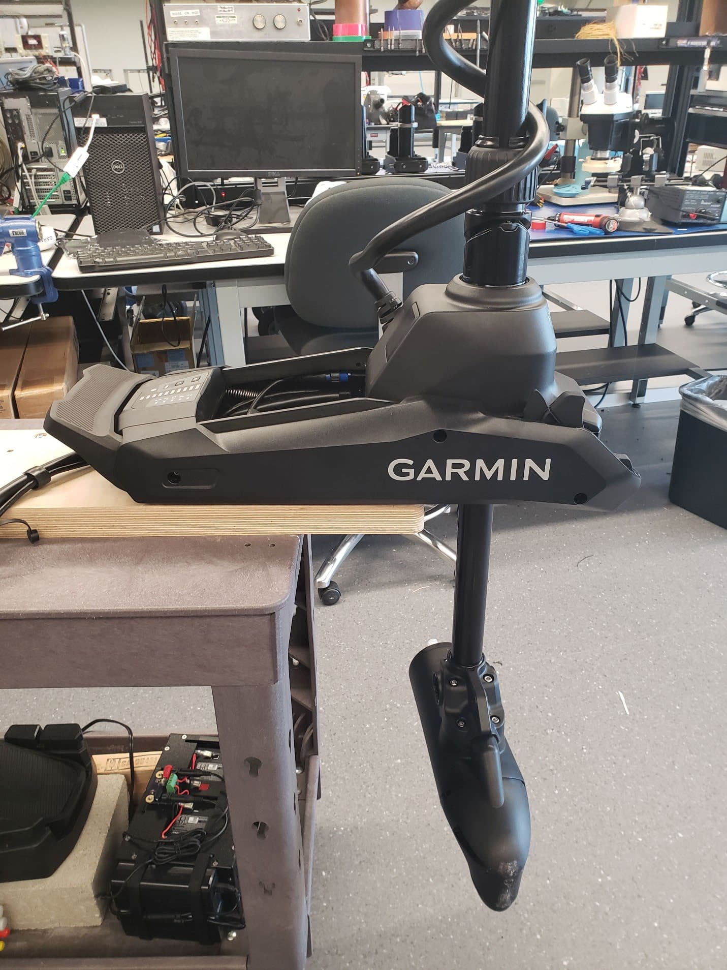
Click to zoom
Application Details
- Equipment Class
- DTS - Digital Transmission System
- Date of Grant
- Jul 05, 2023
- Application Purpose
- Original Equipment
- Date of Application
- Jun 22, 2023
- Equipment Note
- Mobile Transceiver
- Frequency Range
- 2412.00000000 - 2462.00000000
- Company
- Garmin International Inc
- Country
- United States
Documents & Files
Document Text
Text extracted from the exhibit documents filed with the FCC. Open a document above to read the original.
Users Manual
IMPORTANT SAFETY AND PRODUCT INFORMATION WARNING Failure to heed the following warnings could result in an accident or collision resulting in death or serious injury. Trolling Motor Warnings • Do not run the motor when the propeller is out of the water. Contact with the rotating propeller may result in severe injury. • You are responsible for the safe and prudent operation of your vessel. The autopilot features on the trolling motor are tools that enhance your capability to operate your boat. They do not relieve you of the responsibility of safely operating your boat. Avoid navigational hazards and never leave the motor controls unattended. • Learn to operate the autopilot features on calm and hazard-free open water. • Use caution when using operating the trolling motor near hazards in the water, such as trees, shallow rocks, docks, pilings, and other boats. • Always disconnect the motor from the battery before cleaning or servicing the propeller to avoid injury. • Do not use the motor in areas where you or other people in the water may come into contact with the rotating propeller. Battery Warnings Replaceable lithium, alkaline, or NiMH batteries can be used with the remote control and foot pedal. If these guidelines are not followed, batteries may experience a shortened life span or may present a risk of damage to the device, fire, chemical burn, electrolyte leak, and/or injury. • Do not disassemble, modify, remanufacture, puncture or damage the device or batteries. • Do not expose the device or batteries to fire, explosion, or other hazard. • Do not use a sharp object to remove the removable batteries. • KEEP BATTERIES AWAY FROM CHILDREN. NEVER PUT BATTERIES IN MOUTH. Swallowing can lead to chemical burns, perforation of soft tissue, and death. Severe burns can occur within 2 hours of ingestion. Seek medical attention immediately. • Only replace batteries with correct replacement batteries. Using other batteries presents a risk of fire or explosion. CAUTION Failure to heed the following cautions could result in minor or moderate injury, or property damage. Trolling Motor Cautions • When using the autopilot features, be prepared for sudden stops, acceleration, and turns. • When stowing or deploying the motor, be aware of the risk of entrapment or pinching from moving parts, which can result in injury. • When stowing or deploying the motor, be aware of slick surfaces around the motor. Slipping when stowing or deploying the motor may result in injury. NOTICE Failure to heed the following notices could result in personal or property damage, or negatively impact the device functionality. Battery Notice Contact your local waste disposal department to dispose of the device/batteries in accordance with applicable local laws and regulations. GPS Notice The navigation device may experience degraded performance if you use it in proximity to any device that uses a terrestrial broadband network operating close to the frequencies used by any Global Navigation Satellite System (GNSS), such as the Global Positioning Service (GPS). Use of such devices may impair reception of GNSS signals. Product Environmental Programs Information about the Garmin ® product recycling program and WEEE, RoHS, REACH, and other compliance programs can be found at www.garmin.com/aboutGarmin /environment. Declaration of Conformity Hereby, Garmin declares that this product is in compliance with the Directive 2014/53/ EU. The full text of the EU declaration of conformity is available at the following internet address: www.garmin.com/compliance. UK Declaration of Conformity Hereby, Garmin declares that this product is in compliance with the relevant statutory requirements. The full text of the declaration of conformity is available at the following internet address: www.garmin.com/compliance. FCC Compliance This device complies with part 15 of the FCC Rules. Operation is subject to the following two conditions: (1) this device may not cause harmful interference, and (2) this device must accept any interference received, including interference that may cause undesired operation. This equipment has been tested and found to comply with the limits for a Class B digital device, pursuant to part 15 of the FCC rules. These limits are designed to provide reasonable protection against harmful interference in a residential installation. This equipment generates, uses, and can radiate radio frequency energy and may cause harmful interference to radio communications if not installed and used in accordance with the instructions. However, there is no guarantee that interference will not occur in a particular installation. If this equipment does cause harmful interference to radio or television reception, which can be determined by turning the equipment off and on, the user is encouraged to try to correct the interference by one of the following measures: • Reorient or relocate the receiving antenna. • Increase the separation between the equipment and the receiver. • Connect the equipment into an outlet on a circuit different from that to which the receiver is connected. • Consult the dealer or an experienced radio/TV technician for help. This product does not contain any user-serviceable parts. Repairs should only be made by an authorized Garmin service center. Unauthorized repairs or modifications could result in permanent damage to the equipment, and void your warranty and your authority to operate this device under Part 15 regulations. Radio Frequency Radiation Exposure This device is a mobile transmitter and receiver that uses an internal antenna to send and receive low levels of radio frequency (RF) energy for data communications. The device emits RF energy below the published limits when operating in its maximum output power mode and when used with Garmin authorized accessories. To comply with RF exposure compliance requirements, the device should be installed and operated with a minimum of 20 cm (7.87 in.) between the device and your…
Text truncated - open the document above for the full version.
Users Manual
FORCE ® KRAKEN TROLLING MOTOR Quick Start Manual..................................2 Manuel de démarrage rapide ..................11 Force ® Kraken Trolling Motor Quick Start Manual Getting Started WARNING Do not run the motor when the propeller is out of the water. Contact with the rotating propeller may result in severe injury. Do not use the motor in areas where you or other people in the water may come into contact with the rotating propeller. You are responsible for the safe and prudent operation of your vessel. The autopilot features on the trolling motor are tools that enhance your capability to operate your boat. They do not relieve you of the responsibility of safely operating your boat. Avoid navigational hazards and never leave the motor controls unattended. Learn to operate the autopilot features on calm and hazard-free open water. Use caution when operating the trolling motor near hazards in the water, such as trees, shallow rocks, docks, pilings, and other boats. Always disconnect the motor from the battery before cleaning or servicing the propeller to avoid injury. CAUTION Always keep the remote control on your person when using the trolling motor. If the operation of the trolling motor needs to be changed or stopped at any time, you can press on the remote control, press on the foot pedal, or press on the mount to stop the propeller. When using the autopilot features, be prepared for sudden stops, acceleration, and turns. When stowing or deploying the motor, be aware of the risk of entrapment or pinching from moving parts, which can result in injury. When stowing or deploying the motor, be aware of slick surfaces around the motor. Slipping when stowing or deploying the motor may result in injury. Installing Batteries The remote control operates using two AA batteries (not included). Use lithium batteries for best results. 1Turn the D-ring counter-clockwise, and pull up to remove the cover. 2Insert two AA batteries, observing polarity. 3Replace the battery cover, and turn the D-ring clockwise. Attaching a Lanyard 1Starting from the back of the remote control, insert the loop of the lanyard through the slot. 2Quick Start Manual EN 2Thread the other end of the lanyard through the loop, and pull it tight. 3If necessary, place the lanyard around your neck or wrist to tether it during use. Deploying the Motor from the Stowed Position 1Hold down the pedal to release the latch . 2Slide the motor out and release the pedal, and then lower the motor slowly into the deployed position. 3If necessary, push the shaft away to lock the motor in the deployed position. Adjusting the Depth of the Trolling Motor 1Stow the motor. 2Loosen the collar on the motor shaft. 3Slide the collar to raise or lower the depth of the trolling motor. NOTICE Do not set the motor depth so low that it compresses the coiled cable. When the coiled cable is compressed, it will be damaged by friction as the motor steers, and may cause unexpected movement when using the anchor lock feature. 4Tighten the collar. 5Deploy the motor to check the depth. 6Repeat this procedure if necessary to set the correct depth. Stowing the Motor from the Deployed Position NOTICE You must allow the drive motor to stop rotating completely to one side before moving it to the stowed position. If the motor is still rotating to one side when you move it to the stowed position, it may damage the steering system. 1Hold down the pedal to release the latch . Quick Start Manual 3 EN 2Pull the shaft back , and then raise the motor slowly. 3Slide the motor into the motor catch until it locks in the stowed position . Updating the Software You should update the trolling motor software for the best performance. Use the ActiveCaptain ® app on your compatible smartphone to download and install software updates on the trolling motor. See the online owner's manual for more information (page 10). Operation You can use the remote control, the foot pedal, a compatible Garmin ® chartplotter, or a combination of these devices to operate the trolling motor. In general, most of the instructions provided for the remote control also apply to a connected chartplotter. For specific chartplotter instructions, see the latest owner's manual for your chartplotter. NOTE: Some features available when using the remote control and chartplotter are not available when using the foot pedal only. Trolling Motor Display Panel The display panel on the trolling motor mount shows important information at a glance. Speed Shows the motor speed level. Trolling motor battery status Green: the motor battery voltage is good. Yellow: the motor battery voltage is low. Red: the motor battery voltage is critically low. GPS signal status Green: the motor has a good GPS signal. Yellow: the motor has a poor GPS signal. Red: the motor does not have a GPS signal. Motor status Green: the motor is operating normally. Red (solid): the motor software is starting up. Red (blinking): there is a system error. Blue: the motor is in pairing mode. Yellow: the motor is in recovery mode (for software updates and recovery procedures). 4Quick Start Manual EN Power Hold to turn the motor off. NOTE: By default, the trolling motor turns on automatically when it receives power. It is not necessary to push this button to turn it on. When the propeller is turning, press to stop the propeller. Press three times to enter pairing mode. Propeller status Illuminates when the propeller is on. Heading hold status Illuminates when heading hold is on. Anchor lock status Illuminates when anchor lock is on. Press to turn on anchor lock. Hold to turn off anchor lock. Remote Control Buttons Button Description Hold to turn the remote control on and off. Press to turn on and set the cruise control at the current speed over ground (SOG). Press to disable the cruise control and return to manual speed control. If the propeller is on, press to set it to full speed. If the propeller is off, press to enable the propeller and set it to f…
Text truncated - open the document above for the full version.
Users Manual
FORCE ® KRAKEN TROLLING MOTOR Garmin ® , the Garmin logo, ActiveCaptain ® , and Force ® are trademarks of Garmin Ltd. or its subsidiaries, registered in the USA and other countries. These trademarks may not be used without the express permission of Garmin. You should reference United States Code of Federal Regulations: 33 CFR 183 - Boats and Associated Equipment and ABYC E-11: AC and DC Electrical Systems on Boats when installing this trolling motor. El número de registro COFETEL/IFETEL puede ser revisado en el manual a través de la siguiente página de internet. Installation Instructions.......................2 Instructions d'installation .....................6 Printed in Taiwan June 2023 190-03009-02_0A Force ® Kraken Trolling Motor Installation Instructions Getting Started WARNING See the Important Safety and Product Information guide in the product box for product warnings and other important information. Do not run the motor when the propeller is out of the water. Contact with the rotating propeller may result in severe injury. Failure to follow these warnings, cautions, and notices could result in personal injury, damage to the vessel or device, or poor product performance. Do not use the motor in areas where you or other people in the water may come into contact with the rotating propeller. Always disconnect the motor from the battery before cleaning or servicing the propeller to avoid injury. CAUTION To avoid possible personal injury, always wear safety goggles, ear protection, and a dust mask when drilling, cutting, or sanding. When stowing or deploying the motor, be aware of the risk of entrapment or pinching from moving parts, which can result in injury. When stowing or deploying the motor, be aware of slick surfaces around the motor. Slipping when stowing or deploying the motor may result in injury. NOTICE When drilling or cutting, always check what is on the opposite side of the surface to avoid damaging the vessel. Tools and Supplies Needed • Drill and a 5 / 16 in. (8 mm) drill bit • #2 Phillips screwdriver • 4 mm hex bit or wrench • 9 / 16 in. (14 mm) socket • Torque wrench • Circuit breaker rated for continuous 60 A • Trolling motor plug and receptacle rated for 60 A or greater (optional) • 6, 4, or 2 AWG (16, 25, or 35 mm 2 ) wire for extended runs of the power cable • Solder and heat-shrink tubing, if extending the power cable • Stainless steel pan head 1 / 4 -20 (M6x1) bolts (if the included bolts are not long enough to mount the motor to the deck) Installation Preparation Device Overview Shaft cap Power and transducer cables Depth-adjustment collar Steering system Mount Shaft Propeller drive motor Mounting Considerations When selecting a mounting location, observe these considerations. • You must install the motor on the bow of your boat. • You should install the mount so the deployed motor is as close to the center of the boat as possible. • You must install the mount with the top of the cutout overhanging the gunwale of the boat. The U shape should be over the side of the boat. • The motor secures to the deck of the boat using bolts, so you must have room to secure the mount from the underside using washers and nuts. • The motor must have clearance to move from the deployed to the stowed position and back again, so the installation location must be clear of obstacles. • Verify that the deck is strong enough for the weight and force of the trolling motor. Use a backing plate or reinforce the boat if needed. Connection Considerations When making the wiring connections, observe the following considerations. • You must connect the trolling motor to a 24 or 36 Vdc battery bank capable of supplying 60 A continuously. • You must connect to the power source through a circuit breaker rated for continuous 60 A (not included). • If necessary, you can extend the power cable using the appropriate wire gauge based on the length of the extension (Power Cable Extension, page 4). • For convenience, you can install a trolling motor plug and receptacle rated for 60 A or greater (not included) in the bulkhead to make it easier to disconnect the motor from the power source. 2Installation Instructions Installation Procedures NOTICE When assembling the motor, you must use hand tools to install all of the parts, observing the torque specifications when provided. Using power tools to assemble the motor may damage the components, and voids the warranty. Installing the Motor on the Deck NOTE: If the supplied bolts are not long enough for the mounting surface, you must obtain the appropriate length stainless steel pan head 1 / 4 in. -20 (M6x1) bolts. 1Select a mounting location on the bow of your boat, according to the mounting considerations. 2Place the included mounting template on the mounting location with the mount on the template overhanging the gunwale or the edge of the boat deck. 3Mark the mounting hole locations on the boat deck. 4Using a 5 / 16 in. (8 mm) drill bit, drill the mounting holes. 5Place the motor on the boat deck, aligning the holes on the mount with the mounting holes. 6Secure the mount to the deck using the included bolts , washers , and locking nuts in the two holes closest to the gunwale or edge of the boat deck. 7Adjust the depth stop so that the motor can deploy without hitting the ground. 8Press the release , slide the propeller drive motor head out , and pivot the trolling motor into the deployed position . 9Secure the mount to the deck using the included bolts , washers , and locking nuts in the remaining holes. 10Tighten the nuts to a torque of 10.85 N-m (8 lbf-ft.). Installing the Nose Cone NOTE: Most models come fully assembled. This procedure is only required for the 90-inch Force ® Kraken Trolling Motor. Using a 4 mm hex bit or wrench, secure the nose cone to the front of the propeller drive motor using the two included screws, ensuring the tab is on the bottom. Installing the Skeg NOTE: Most models come fully assembled. This procedure is only required for t…
Text truncated - open the document above for the full version.
Attestation Statements
R ev 1/26/2023 Federal Communications Commission Authorization and Evaluation Division 7435 Oakland Mills Road Columbia, MD 21046 USA Date: June 15, 2023 Ref: Attestation Statements Part 2.911(d)(5)(i) Filing FCC ID: IPH- 04109 FRN: 0005088588 Garmin International, Inc., (“the applicant”) certifies that the equipment for which authorization is sought is not “covered” equipment prohibited from receiving an equipment authorization pursuant to section 2.903 of the FCC rules. Sincerely, Ben Karsak
Attestation Statements
Federal Communications Commission Authorization and Evaluation Division 7435 Oakland Mills Road Columbia, MD 21046 USA Date: June 15, 2023 Ref: Attestation Statements Part 2.911(d)(7) Filing FCC ID: IPH-04109 Garmin International, Inc., Garmin certifies that, as of the date of t he filing of the application, Garmin International, Inc.. is our designated U.S. agent for service of process for the above referenced FCC ID. Garmin International, Inc., accepts to maintain an agent for no less than one year after the grantee has terminated all marketing and importation or t he conclusion of any Commission-related proceeding involving the equipment. Garmin International, Inc. accepts, as of the date of t he filing of the application, the obligation of the designated U.S. agent for service of process for t he above referenced FCC ID. Designated U.S. Agent Information: FRN: 0005088588 Name: Garmin International, Inc. Address: 1200 East 151 st Street, Olathe, Kansas, 66062 Contact Person: Ben Karsak Tel.: 913-397-1946 Email: [email protected] Sincerely, Garmin International, Inc. Ben Karsak
Attestation Statements
R ev 1/26/2023 Federal Communications Commission Authorization and Evaluation Division 7435 Oakland Mills Road Columbia, MD 21046 USA Date: June 15, 2023 Ref: Attestation Statements Part 2.911(d)(5)(ii) Filing FCC ID: IPH- 04109 FRN: 0005088588 Garmin International, Inc., (“the applicant”) certifies that, as of the date of t he filing of the application, the applicant is not identified on the Covered List as an entity producing “covered” equipment. Sincerely, Ben Karsak
Cover Letter(s)
June 21, 2023 Federal Communications Commission Authorization and Evaluation Division 1435 Oakland Mills Road Columbia, MD 21046 Innovation, Science and Economic Development Canada Certification and Engineering Bureau 3701 Carling Avenue PO Box 11490, Station H Ottawa, Ontario, Canada K2H 8S2 To Whom It May Concern: Pursuant to 47 CFR 2.911, Garmin International, Inc. (Garmin) has authorized the following Garmin International Associates to act on Garmin's behalf for the sole and express purpose of processing applications to the Federal Communication Commission (FCC) and Innovation, Science and Economic Development Canada (ISED) for equipment authorization or certification. Mr. Chris Strauss, Compliance Engineering Team Lead Mr. William Pertner, Compliance Engineering Team Lead Mr. Jay Everett, Compliance Engineering Team Lead Mr. Mike Moranha, Compliance Engineer Ms. Poojita Bhattu, Compliance Engineer Mr. Jeffrey Hailey, Compliance Engineer Mr. Dan Irish, Compliance Engineer Mr. Kiran Kumar, Compliance Engineer Mr. Tim Olson, Compliance Engineer Mr. Carlos Ortega, Compliance Engineer Mr. David Utt, Staff Compliance Engineer Mr. Jonathan Shafer, Design Certification Engineer Ms. Sara Jones, Design Certification Engineer Mr. Jacky Yeung, Compliance Engineer As such, the Garmin Associates listed above are authorized to: 1) sign Form 731, 2) sign letters of application, 3) request confidentiality, and 4) exchange data and information with the FCC, IC and/or authorized TCBs on behalf of Garmin. In addition, these individuals shall be considered "authorized individuals" to act on Garmin's behalf where an "authorized individual's" attestation is necessary or preferred. This authorization remains in effect until notified to the contrary by Garmin. Sincerely, Ben Karsak Manager Compliance Engineering Garmin International, Inc.
Cover Letter(s)
June 8, 2023 Federal Communications Commission Equip Approval Services Post Office Box 358315 Pittsburgh, Pennsylvania 15215-5315 To Whom It May Concern: Pursuant to 47 CFR 2.911, Garmin International, Inc. (Garmin) has authorized Nic Johnson, Technical Manager, NCEE Labs, 4740 Discovery Dr, Lincoln, NE 68521 to act on Garmin’s behalf for the sole and express purpose of processing applications to the Federal Communication Commission (FCC) for equipment FCC authorization. This authorization is limited to FCC ID: IPH-04109 Consistent with the foregoing, Ni c Johnson is authorized to: 1) Sign Form 731, 2) Sign letters of application, 3) Request confidentiality, and 4) Exchange data and information with the FCC, and authorized TCBs on behalf of Garmin. This authorization is not assignable to others beyond Nic Johnson. No party to this application is subject to a denial of benefits, including FCC benefits, pursuant to Section 5301 of the Anti- Drug Abuse Act of 1988, 21 U.S.C 862. We also declare that the information provided to the FCC is true and correct to the best of our knowledge (47 CFR 2.911(d)) and we have been informed of the grantee responsibilities (47 CFR 2.909) with regard to certified equipment. This authorization expires June 8, 2024 Sincerely, Jeffrey Hailey Staff Compliance Engineer Garmin International
Cover Letter(s)
Page 1 of 1 Request for Confidentiality Date: June 15, 2023 Subject: Confidentiality Request for: FCC ID: IPH-04109 IC: 1792A-04109 Pursuant to FCC 47 CFR 0.457(d) and 0.459 and IC RSP-100, Section 12.4, the applicant requests that a part of the subject FCC application be held confidential. Type of Confidentiality Requested Exhibit ☐ Short Term ☒ Permanent ☐ Not Provided Block Diagrams ☒ Short Term ☐ Not Provided External Photos ☒ Short Term ☐ Permanent ☐ Not Provided Internal Photos ☐ Short Term ☒ Permanent ☐ Not Provided Operation Description/Theory of Operation ☐ Short Term ☐ Permanent ☒ Not Provided Parts List & Placement/BOM ☐ Short Term ☐ Permanent ☒ Not Provided Tune-Up Procedure ☐ Short Term ☒ Permanent ☐ Not Provided Schematics ☒ Short Term ☐ Not Provided Test Setup Photos ☒ Short Term ☐ Permanent ☐ Not Provided User’s Manual The above-mentioned company has spent substantial effort in developing this product and it is one of the first of its kind in industry. Having the subject information easily available to "competition" would negate the advantage they have achieved by developing this product. Not protecting the details of the design will result in financial hardship. Permanent Confidentiality: The applicant requests the exhibits listed above as permanently confidential be permanently withheld from public review due to materials that contain trade secrets and proprietary information not customarily released to the public. Short-Term Confidentiality (if applicable): The applicant requests the exhibits selected above as short term confidential be withheld from public view for a period of 180 days from the date of the Grant of Equipment Authorization and prior to marketing. This is to avoid premature release of sensitive information prior to marketing or release of the product to the public. Applicant is also aware that they are responsible to notify Timco in the event information regarding the product or the product is made available to the public before the requested period has expired. Timco will then release the documents listed above for public disclosure pursuant to FCC Public Notice DA 04- 1705. Sincerely, By: __________________________ Nic Johnson, Technical Manager, NCEE Labs
Cover Letter(s)
June 21, 2023 Federal Communications Commission 7435 Oakland Mills Road Columbia MD 21046 Subject: Grant Deferral Date Change FCC ID: IPH-04109 To Whom It May Concern: Please defer the grant date for Garmin International, Inc., FCC ID: IPH-04109 until July 6, 2023. Best Regards, Nic Johnson Technical Manager NCEE Labs [email protected]
External Photos
A04109 External Photos Compliance Label Loca�on
ID Label/Location Info
A04109 Label Drawing and Placement Bottom of device M/N: A04109 IC: 1792A-04109 FCC ID: IPH-04109 This device complies with part 15 of the FCC Rules. Operation is subject to the following two conditions: (1) This device may not cause harmful interference, and (2) this device must accept any interference received, including interference that may cause undesired operation. Label Device
Internal Photos
A04109 Internal Photos
RF Exposure Info
Page 1 of 4 MPE Evaluation Approved By: __________________ Fox Lane, EMC Test Engineer Summary and Operating Condition: EUT A04109 IC IPH-04109 FCC ID 1792A-04109 EUT Received 3 March 2023 EUT Tested 3 March 2023- 17 April 2023 Serial No. FF7 (Radiated Measurements) 010966 (Lab Assigned Serial Number) (Conducted Measurements) Operating Band 2400 – 2483.5 MHz Device Type ☒ GMSK ☐ GFSK ☐ BT BR ☐ BT EDR 2MB ☐ BT EDR 3MB ☐ 802.11x Power Supply / Voltage 30VDC lithium battery pack NOTE: For more detailed features description, please refer to the manufacturer's specifications or user's manual. Page 2 of 4 FCC Maximum exposure limits from CFR 47, FCC Part 1.1310: Table 1—Limits for Maximum Permissible Exposure (MPE) Frequency range (MHz) Electric field strength (V/m) Magnetic field strength (A/m) Power density (mW/cm 2 ) Averaging time (minutes) (A) Limits for Occupational/Controlled Exposure 0.3-3.0 614 1.63 *100 6 3.0-30 1842/f 4.89/f *900/f 2 6 30-300 61.4 0.163 1.0 6 300-1,500 f/300 6 1,500-100,000 5 6 (B) Limits for General Population/Uncontrolled Exposure 0.3-1.34 614 1.63 *100 30 1.34-30 824/f 2.19/f *180/f 2 30 30-300 27.5 0.073 0.2 30 300-1,500 f/1500 30 1,500-100,000 1.0 30 Page 3 of 4 Table 1 - Power Density Calculations, FCC Occupational/Controlled ☐ General Population/uncontrolled ☒ FCC Power Density Calculations Frequency Radiated Power Antenna Gain Peak Power EIRP Peak Power EIRP +10% for Tolerance Power Density Limit at specified distance % of limit Result MHz mW numerical mW mW mW/cm^2 mW/cm^2 % 2402 2.54 1.28 3.25 3.58 0.001 1.00 0.071 PASS 2440 2.22 1.28 2.84 3.13 0.001 1.00 0.062 PASS 2480 1.88 1.28 2.41 2.65 0.001 1.00 0.053 PASS Distance (d) 20 cm S = (P x G)/(4 x π x d^2) – used to calculate exposure at "d" cm EIRP = P x G, measured as field strength d = √(S/(P x G) x 4 X π) – used to calculate minimum distance to meet limits Note: The user’s manual will stipulate that a 20cm minimum distance from the user is to be maintained. EIRP values in mW were multiplied by 1.1 to account for a 10% tolerance. S= power density P = transmitter conducted power (in mW) G = antenna numeric gain d = distance to radiation center (20 cm) Page 4 of 4 IC / ISED Using RSS-102, Issue 5, Section 2.5.2 RF exposure evaluation is required if the separation distance between the user and/or bystander and the device’s radiating element is greater than 20 cm, except when the device operates as follows: • below 20 MHz6 and the source-based, time-averaged maximum e.i.r.p. of the device is equal to or less than 1 W (adjusted for tune-up tolerance); • at or above 20 MHz and below 48 MHz and the source-based, time-averaged maximum e.i.r.p. of the device is equal to or less than 4.49/ƒ0.5 W (adjusted for tune-up tolerance), where ƒ is in MHz; • at or above 48 MHz and below 300 MHz and the source-based, time-averaged maximum e.i.r.p. of the device is equal to or less than 0.6 W (adjusted for tune-up tolerance); • at or above 300 MHz and below 6 GHz and the source-based, time-averaged maximum e.i.r.p. of the device is equal to or less than 1.31 x 10⁻² ƒ^(0.6834) W (adjusted for tune-up tolerance), where ƒ is in MHz. • at or above 6 GHz and the source-based, time-averaged maximum e.i.r.p. of the device is equal to or less than 5 W (adjusted for tune-up tolerance). In these cases, the information contained in the RF exposure. Table 2 - Power Density Calculations, IC/ISED IPH-04109 Frequency Conducted Power Antenna Gain Numerical Peak EIRP Power EIRP +10% Tolerance Exemption Limit Result MHz mW Num. mW mW mW 2402.00 2.82 1.28 3.61 3.97 2676.42 PASS 2440.00 2.53 1.28 3.24 3.56 2676.42 PASS 2480.00 2.00 1.28 2.56 2.82 2676.42 PASS
RF Exposure Info
Page 1 of 4 MPE Evaluation Approved By: _____…
Text truncated - open the document above for the full version.
Contact Information
Applicant
Ben Karsak(Manager, Compliance Engineering)
Test Firm
Nebraska Center for Excellence in ElectronicsKarthik Vepuri
Technical Specifications
| # | Rule Parts | Frequency Range | Power Output |
|---|---|---|---|
| 2 | 15C | 2.41 GHz - 2.46 GHz | 51.17 mW |
Other Applications from Garmin International Inc
IPH-05126
Sep 09, 2026Portable Digital Transceiver
Equipment Class
NII - Unlicensed National Information Infrastructure TXIPH-A5126
Sep 09, 2026Portable Digital Transceiver
Equipment Class
NII - Unlicensed National Information Infrastructure TXIPH-04812
Sep 01, 2026Mobile Digital Transceiver
Equipment Class
DTS - Digital Transmission SystemIPH-A04825
Sep 01, 2026Marine Stereo
Equipment Class
DSS - Part 15 Spread Spectrum TransmitterIPH-B04825
Sep 01, 2026Marine Stereo
Equipment Class
DSS - Part 15 Spread Spectrum Transmitter