IPH-A2AVGC00Connected Personal Navigation Device
Garmin International Inc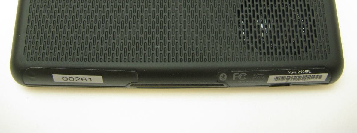
Click to zoom
Application Details
- Equipment Class
- PCB - PCS Licensed Transmitter
- Date of Grant
- Jul 02, 2012
- Application Purpose
- Original Equipment
- Date of Application
- Jul 02, 2012
- Equipment Note
- Connected Personal Navigation Device
- Frequency Range
- 1712.40000000 - 1752.60000000
- Company
- Garmin International Inc
- Country
- United States
Documents & Files
Document Text
Text extracted from the exhibit documents filed with the FCC. Open a document above to read the original.
Users Manual
Important Safety and Product Information WARNING Failure to avoid the following potentially hazardous situations could result in an accident or collision resulting in death or serious injury. Installation and Operation Warnings • When installing the device in a vehicle, place the device securely so it does not obstruct the driver’s view of the road or interfere with vehicle operating controls, such as the steering wheel, the foot pedals, or the transmission levers. Do not place the device in front of or above any airbag. (See diagram.) Do not mount where driver’s field of vision is blocked. Do not place unsecured on the vehicle dashboard. Do not mount in front of an airbag field of deployment. • The windshield mount may not stay attached to the windshield in all circumstances. Do not place the mount where it will become a distraction if the mount should become detached. Keep your windshield clean to help ensure that the mount stays on the windshield. • Always use your best judgement, and operate the vehicle in a safe manner. Do not become distracted by the device while driving, and always be fully aware of all driving conditions. Minimize the amount of time spent viewing the device screen while driving and use voice prompts when possible. • Do not input destinations, change settings, or access any functions requiring prolonged use of the device controls while driving. Pull over in a safe and legal manner before attempting such operations. • When navigating, carefully compare information displayed on the device to all available navigation sources, including road signs, road closures, road conditions, traffic congestion, weather conditions, and other factors that may affect safety while driving. For safety, always resolve any discrepancies before continuing navigation, and defer to posted road signs and road conditions. • The device is designed to provide route suggestions. It is not a replacement for driver attentiveness and good judgement. Do not follow route suggestions if they suggest an unsafe or illegal maneuver or would place the vehicle in an unsafe situation. Battery Warnings If these guidelines are not followed, the internal lithium-ion battery may experience a shortened life span or may present a risk of damage to the GPS device, fire, chemical burn, electrolyte leak, and/or injury. • Do not leave the device exposed to a heat source or in a high-temperature location, such as in the sun in an unattended vehicle. To prevent damage, remove the device from the vehicle or store it out of direct sunlight, such as in the glove box. • Do not puncture or incinerate the device or battery. • When storing the device for an extended time, store within the following temperature range: from 32° to 77°F (from 0° to 25°C). • Do not operate the device outside of the following temperature range: from -4° to 131°F (from -20° to 55°C). • Contact your local waste disposal department to dispose of the device/battery in accordance with applicable local laws and regulations. Additional User-Replaceable Battery Warnings: • Do not use a sharp object to remove the battery. • Keep the battery away from children. • Do not disassemble, puncture, or damage the battery. • If using an external battery charger, only use the Garmin accessory approved for your product. 190-01505-90_0C.indd 110/10/2012 8:02:25 AM • Only replace the battery with the correct replacement battery. Using another battery presents a risk of fire or explosion. To purchase a replacement battery, see your Garmin dealer or the Garmin Web site. Additional Non-User-Replaceable Battery Warning: • Do not remove or attempt to remove the non-user- replaceable battery. NOTICE Windshield Mounting Legal Restrictions Before using the suction cup mount on your windshield, check the state and local laws and ordinances where you drive. Some state laws prohibit drivers from using suction mounts on their windshields while operating motor vehicles. Other state laws allow the suction mount to be located only in specific locations on the windshield. Many other states have enacted restrictions against placing objects on the windshield in locations that obstruct the driver’s vision. IT IS THE USER’S RESPONSIBILITY TO MOUNT THE GARMIN DEVICE IN COMPLIANCE WITH ALL APPLICABLE LAWS AND ORDINANCES. Where required, other Garmin dashboard or friction mount options should be used. Always mount your Garmin device in a location that does not obstruct the driver’s view of the road. Garmin does not assume any responsibility for any fines, penalties, or damages that may be incurred as a result of any state or local law or ordinance relating to the use of your Garmin device. Map Data Information Garmin uses a combination of governmental and private data sources. Virtually all data sources contain some inaccurate or incomplete data. In some countries, complete and accurate map information is either not available or is prohibitively expensive. Radio Frequency Exposure This device is a mobile transmitter and receiver that uses its antenna to send and receive low levels of radio frequency (RF) energy for data communications. The device emits RF energy below the published limits when operating in its maximum output power mode and when used with Garmin authorized accessories. To comply with FCC and Industry Canada RF exposure compliance requirements, the device should be used in its automobile mount or as a handheld device only. The device should not be used in other configurations. This device has been shown to be compliant with FCC RF exposure requirements for a minimum distance of 10mm between the device and the body and zero distance for hand operation. This device must not be co-located or operated in conjunction with any other transmitter or antenna. For actual SAR values, go to http://www.garmin.com /compliance. FCC Compliance This device complies with part 15 of the FCC Rules. Operation is subject to the following two conditions: (1) this device may not cause harmful inte…
Text truncated - open the document above for the full version.
Attestation Statements
To Whom It May Concern: Subject: Final Version of User Manual WE, Garmin International of 1200 East 151st Street, Olathe, KS 66062, This is to confirm that the final version of the user manual will be provided to the certifying FCC- TCB / IC-CB for upload to the FCC EAS and IC REL once final translations are done. This will be before the product launches and will contain all necessary updates that have been stipulated by the TCB. Van Ruggles 6/29/2012
Attestation Statements
To Whom It May Concern: Subject: Validity of Test Results from Testing / Certification of an integrated Module WE, Garmin International of 1200 East 151st Street, Olathe, KS 66062, This is to confirm that that the results from conducted FCC part 22/24/27 and IC RSS-132/133/139 emc/radio tests applied for the purpose of FCC and IC certification to the licensed cellular radio module Model: HE910-D, FCC ID: RI7HE910, IC: 5131A-HE910 which is incorporated in our host equipment Model / Name: A2AVGC00 / nüvi 2598FL, FCC ID: IPH-A2AVGC00, IC: 1792A-A2AVGC00 and as reported in module test report(s) #1112FR12-02 of 02/03/2012 issued by A Test Lab Techno Corp., Taiwan #1201FR11-02 of 02/03/2012 issued by A Test Lab Techno Corp., Taiwan accurately represent the test results under the new conditions when the identified radio module is integrated in the identified host equipment. By integration of the said radio odule into the identified host equipment no changes were made to it or by external adaptation circuitry that impacts the validity of the results of the original module’s test reports. Van Ruggles 6/27/2012
Cover Letter(s)
5/28/2012 Federal Communications Commission Authorization and Evaluation Division 7435 Oakland Mills Road Columbia, MD 21046 Attn: OET Dept. Ref: FCC ID: IPH-A2AVGC00 Applicant: Garmin International Inc Dear Examiner, We the undersigned, hereby authorize Heiko Strehlow, Director of Regulatory and Antenna Services(Cetecom, Inc., 411 Dixon Landing Road, Milpitas, CA 95035, Tel.408 586 6214) to act on our behalf in all manners relating to application for equipment authorization, including signing of all documents relating to these matters. Any and all acts carried out by CETECOM Inc., on our behalf shall have the same effect as acts of our own. The authorization from Garmin International Inc is valid for 30 days from the date of this letter. Sincerely, Jay Everett Certification Team Lead Garmin International Inc
Cover Letter(s)
5/28/2012 Permanent Confidentiality Request – IPH-A2AVGC00 Dear FCC Reviewer, Pursuant to Sections 0.457(d)(ii) and 0.459 of the Commission’s Rules, Garmin International hereby requests permanent confidential treatment of information accompanying this application as outlined below: Block Diagrams Operational Descriptions Part Lists Tune-up Procedures Schematics The above materials contain proprietary Garmin trade secrets and other information not customarily released to the public before product launch. The public disclosure of these matters might be harmful to the Applicant and provide unjustified benefits to its competitors. The Applicant also understands that pursuant to Rule 0.457(d)(1)(ii), disclosure of the Application and all accompanying materials will not be made before the date of the Grant for this Application.
Cover Letter(s)
5/28/2012 Short Term Confidentiality Request – IPH-A2AVGC00 Dear FCC Reviewer, Pursuant to Sections 0.457(d)(ii) and 0.459 of the Commission’s Rules, Garmin International hereby requests short term confidential treatment of information accompanying this application until 45 days from the grant date or August 6, 2012, whichever is first: External Photographs Internal Photographs Test Setup Photographs User Manuals The above materials contain proprietary Garmin trade secrets and other information not customarily released to the public before product launch. The public disclosure of these matters might be harmful to the Applicant and provide unjustified benefits to its competitors. The Applicant also understands that pursuant to Rule 0.457(d)(1)(ii), disclosure of the Application and all accompanying materials will not be made before the date of the Grant for this Application.
Cover Letter(s)
Evidence: STC Extension Request from Grantee towards CETECOM Inc. PM From: Everett, Jay [mailto:[email protected]] Sent: Monday, July 30, 2012 7:48 AM To: Rami Saman Subject: A2AVGC00 Short-Term Confidentiality Extension Rami, The short-term confidentiality documents expire on 8/6/2012 for A2AVGC00. I would like to apply for another 45 days, starting from 8/6/2012. I believe that makes the expiration date 9/20/2012. Is that correct? Thanks, Jay Everett Product and Systems Validation Team Lead Garmin International Direct: 919.337.0163 Mobile: 919.443.5059 [email protected]
Cover Letter(s)
11/15/2012 We the undersigned, would like to supersede documents associated with the certification of IPH- A2AVGC00. The manuals are being superseded so final versions, including translations, can be captured. The documents to be superseded are: A2AVGC00_User_Manual_1 A2AVGC00_User_Manual_2 Sincerely, Jay Everett Certification Team Lead Garmin International
External Photos
IPH-A2AVGC00
ID Label/Location Info
MGR. PROJ. RELEASED BY UNLESS NOTED OTHERWISE ANGLES +/- 0 DEG./30 MIN. HOLES +/-.003”, .08 mm .XXX +/-.005”, .13 mm .XX +/-.010”, .25 mm TOLERANCE CHKD. DRAWN DATE OFSHT. REV. DWG. NO. SCALE SIZE TITLE CONFIDENTIAL This drawing and the specifications contained herein are the property of Garmin Ltd. or its subsidiaries and may not be reproduced or used in whole or in part as the basis for manufacture or sale of products without written permission. TAG, S/N, NUVI 2598FL, NA 161-02483-80 B A 1 1 1X RNL JDT JND JKF 1/26/12 1/26/12 1/27/12 1/30/12 PRODUCTION RELEASE WIDEN BARCODE BACKGROUND AREA 88603 ----- 1/26/12 2/23/12 A B REV. DATE DESCRIPTION APPRVD. REVISIONS SPECIFICATION CONTROL DRAWING c/o Garmin International, Inc. Garmin Ltd. or its subsidiaries 1200 E. 151st Street Olathe, Kansas 66062 U.S.A. NOTES: 1. MATERIAL: WHITE POLYESTER (FOUR PILLARS POB3H). SECOND SURFACE PRINTED. BACKGROUND: PANTONE BLACK C. MODEL NUMBER: WHITE. S/N AREA: PANTONE COOL GRAY 6C (SERIAL NUMBER TO BE BLACK). ALL OTHER COPY PANTONE 425C. ACRYLIC PERMANENT ADHESIVE ON BACKSIDE WITH PEEL OFF RELEASE LINER. TOTAL PACKAGE THICKNESS EXCLUDING RELEASE LINER .0762mm. SCALE: 1X SEE NOTE 2 PRINT LAST 5 DIGITS OF SERIAL NUMBER 2x R0.6 2x 46.7 2 x 1 0 . 7 41.2 14.9 10.3 1 . 8 41.2 2x, R1.75 Made in Taiwan Nuvi 2598FL IC: 1792A-A2AVGC00 FCC ID: IPH-A2AVGC00 M/N:A2AVGC00 2KM000000 2KM000000 XXXXX 2000mA 5V 2. 9 DIGIT SERIAL NUMBER TO BE PRINTED SEQUENTIALLY AS SHOWN (2D DATA MATRIX BARCODE WITH SEPARATE MATCHING HUMAN READABLE CODE). ALSO PRINT ADDITIONAL TAGS (30 X 7.5) IN QTY INDICATED (BARCODE 39 WITH HUMAN READABLE ONLY). ALL S/N INFO PRINTED WITH INDELIBLE BLACK INK. SERIAL NUMBER RANGE FOR THIS ITEM: 2KM000000-2KM999999 AS INDICATED ON GARMIN PURCHASE ORDER. 3. MAIN TAG AND ADDITIONAL TAG ARE SUPPLIED ON ONE ROLL WITH EQUIVALENT SERIAL NO.S ADJACENT TO EACH OTHER. ALL TAGS ARE “KISS CUT” ON ROLL. 4. PARTS TO BE FABRICATED USING DIGITAL CORELDRAW FILE. 5. THIS PART SHALL COMPLY WITH GARMIN BANNED & RESTRICTED SUBSTANCES DOCUMENT GPN 001-00211-00. 6. THIS PART SHALL NOT CONTAIN HAZARDOUS SUBSTANCES EXCEEDING LEVELS DEFINED BY EU DIRECTIVE 2002/95/EC (RoHS).
Internal Photos
IPH-A2AVGC00
RF Exposure Info
FCC Listed #: A2LA Accredited IC Recognized # 3462B-1 CETECOM Inc. 411 Dixon Landing Road Milpitas, CA 95035 U.S.A. Phone: + 1 (408) 586 6200 Fax: + 1 (408) 586 6299 E-mail: [email protected] http://www.cetecom.com CETECOM Inc. is a Delaware Corporation with Corporation number: 2113686 V3.0 2010-12-30 The BLUETOOTH trademarks are owned by Bluetooth SIG, Inc., U.S.A. and licensed to CETECOM Inc. © Copyright by CETECOM SAR Test Report FOR: Manufacturer: Garmin International Model Name: Nuvi 2598FL FCC ID: IPH-A2AVGC00 IC ID: 1792A-A2AVGC00 Test Report #: SAR_GARMI_041_12001_FCC Date of Report: 2012-07-02 Test Report #: SAR_GARMI_041_12001_FCC FCC ID: IC ID: IPH-A2AVGC00 1792A-A2AVGC00 Date of Report : 2012-07-02 Page 2 of 33 V3.0 2010-12-30 This report shall not be reproduced except in full without the written approval of: CETECOM Inc. SAR 411 Dixon Landing Road Milpitas, CA 95035 U.S.A. TABLE OF CONTENTS 1. Assessment ............................................................................................................................ 4 2. Administrative Data ............................................................................................................. 5 2.1. Identification of the Testing Laboratory Issuing the SAR Test Report ............................ 5 2.2. Identification of the Client .................................................................................................... 5 2.3. Identification of the Manufacturer ...................................................................................... 5 3. Equipment under Test (EUT) .............................................................................................. 6 3.1. Specification of the Equipment under Test ......................................................................... 6 3.2. Identification of the Equipment Under Test (EUT) ............................................................ 7 3.1. Identification of Accessory equipment ................................................................................. 7 4. Subject of Investigation ....................................................................................................... 8 4.1. The IEEE Standard C95.1 and the FCC Exposure Criteria.............................................. 8 4.2. Distinction Between Exposed Population, Duration of Exposure and Frequencies ........ 8 4.3. Distinction between Maximum Permissible Exposure and SAR Limits ........................... 9 4.4. SAR Limit ............................................................................................................................... 9 5. The FCC Measurement Procedure and IC Measurement Procedure ............................. 10 5.1. General Requirements ......................................................................................................... 10 5.2. Body-worn and Other Configurations ............................................................................... 10 5.3. Procedure for assessing the peak spatial-average SAR .................................................... 11 5.4. Determination of the largest peak spatial-average SAR .................................................. 13 6. The Measurement System .................................................................................................. 14 6.1. Robot system specification .................................................................................................. 14 6.2. Isotropic E-Field Probe for Dosimetric Measurements ................................................... 15 6.3. Data Acquisition Electronics ............................................................................................... 15 6.4. Phantoms .............................................................................................................................. 15 6.5. Interpolation and Extrapolation schemes .......................................................................... 15 Test Report #: SAR_GARMI_041_12001_FCC FCC ID: IC ID: IPH-A2AVGC00 1792A-A2AVGC00 Date of Report : 2012-07-02 Page 3 of 33 V3.0 2010-12-30 This report shall not be reproduced except in full without the written approval of: CETECOM Inc. SAR 411 Dixon Landing Road Milpitas, CA 95035 U.S.A. 7. Uncertainty Assessment ..................................................................................................... 16 7.1. Measurement Uncertainty Budget ..................................................................................... 16 8. Test results summary ......................................................................................................... 17 8.1. Conducted Average Output Power .................................................................................... 17 8.2. Stand-Alone SAR Evaluation Exclusion ............................................................................ 21 8.3. Test Positions and Configurations ...................................................................................... 22 8.4. SAR Results for Body(1g) and Hand(10g) Exposure ........................................................ 23 8.4.1. GSM 850 Band ..................................................................................................................... 23 8.4.2. PCS 1900 Band ..................................................................................................................... 24 8.4.3. WCDMA FDD V .................................................................................................................. 25 8.4.4. WCDMA FDD IV ................................................................................................................ 25 8.4.5. WCDMA FDD II .................................................................................................................. 26 8.5. SAR Results Extrapolated to Upper Tolerance Limit ...................................................... 27 8.6. Simu…
Text truncated - open the document above for the full version.
RF Exposure Info
SAR Test Report No.: SAR_GARMI_041_12001_FCC FCC ID: IPH-A2AVGC00 IC ID: 1792A-A2AVGC00 Date of Report: 2012-07-02 Appendix A Plots Page 1 of 86 Plot 1: Date/Time: 6/6/2012 3:19:48 PM Test Laboratory: Cetecom Inc., SAR 3 Lab DUT: Garmin; Type: GPS; Serial: U2:2KM000250 Communication System: GPRS 4 TS; Frequency: 836.6 MHz Medium: MSL900_Batch 110518-7 Medium parameters used: f = 836.6 MHz; σ = 0.994 mho/m; ε r = 53.47; ρ = 1000 kg/m 3 Phantom section: Flat Section Measurement Standard: DASY5 (IEEE/IEC/ANSI C63.19-2007) Procedure Notes: Test Technician: Kathy Tran; Air Temperature: 23.8C; Medium Temperature: 22.3C; DASY Configuration: • Probe: ES3DV3 - SN3261; ConvF(6.1, 6.1, 6.1); • Sensor-Surface: 3mm (Mechanical Surface Detection), z = 2.0, 32.0 • Electronics: DAE4 Sn1266; Calibrated: 5/30/2011 • Phantom: SAM Front; Type: QD000P40CD; Serial: TP-1637 • DASY52 52.8.0(692); Flat-Section 6-6/Front 0mm_4Up TS_836.6MHz_u2/Area Scan (8x12x1): Measurement grid: dx=15mm, dy=15mm Maximum value of SAR (measured) = 1.647 mW/g Flat-Section 6-6/Front 0mm_4Up TS_836.6MHz_u2/Zoom Scan (7x7x7)/Cube 0: Measurement grid: dx=5mm, dy=5mm, dz=5mm Reference Value = 20.688 V/m; Power Drift = -0.0054 dB Peak SAR (extrapolated) = 2.4060 SAR(1 g) = 1.38 mW/g; SAR(10 g) = 0.798 mW/g Maximum value of SAR (measured) = 1.674 mW/g 0 dB = 1.670mW/g = 4.45 dB mW/g SAR Test Report No.: SAR_GARMI_041_12001_FCC FCC ID: IPH-A2AVGC00 IC ID: 1792A-A2AVGC00 Date of Report: 2012-07-02 Appendix A Plots Page 2 of 86 Plot 2: Date/Time: 6/7/2012 11:18:15 AM Test Laboratory: Cetecom Inc., SAR 3 Lab DUT: Garmin; Type: GPS; Serial: U4:259 Communication System: GPRS 4 TS; Frequency: 836.6 MHz Medium: MSL900_Batch 110518-7 Medium parameters used: f = 836.6 MHz; σ = 0.996 mho/m; ε r = 53.46; ρ = 1000 kg/m 3 Phantom section: Flat Section Measurement Standard: DASY5 (IEEE/IEC/ANSI C63.19-2007) Procedure Notes: Test Technician: Kathy Tran; Air Temperature: 24.1C; Medium Temperature: 22.3C; DASY Configuration: • Probe: ES3DV3 - SN3261; ConvF(6.1, 6.1, 6.1); • Sensor-Surface: 3mm (Mechanical Surface Detection), z = 2.0, 32.0 • Electronics: DAE4 Sn1266; Calibrated: 5/30/2011 • Phantom: SAM Front; Type: QD000P40CD; Serial: TP-1637 • DASY52 52.8.0(692); Flat-Section 6-7/Front 10mm_4Up TS_836.6MHz_u4/Area Scan (8x12x1): Measurement grid: dx=15mm, dy=15mm Maximum value of SAR (measured) = 0.844 mW/g Flat-Section 6-7/Front 10mm_4Up TS_836.6MHz_u4/Zoom Scan (7x7x7)/Cube 0: Measurement grid: dx=5mm, dy=5mm, dz=5mm Reference Value = 30.414 V/m; Power Drift = -0.17 dB Peak SAR (extrapolated) = 0.9390 SAR(1 g) = 0.768 mW/g; SAR(10 g) = 0.595 mW/g Maximum value of SAR (measured) = 0.840 mW/g 0 dB = 0.840mW/g = -1.51 dB mW/g SAR Test Report No.: SAR_GARMI_041_12001_FCC FCC ID: IPH-A2AVGC00 IC ID: 1792A-A2AVGC00 Date of Report: 2012-07-02 Appendix A Plots Page 3 of 86 Plot 3: Date/Time: 6/6/2012 4:36:29 PM Test Laboratory: Cetecom Inc., SAR 3 Lab DUT: Garmin; Type: GPS; Serial: U2:2KM000250 Communication System: GPRS 4 TS; Frequency: 836.6 MHz Medium: MSL900_Batch 110518-7 Medium parameters used: f = 836.6 MHz; σ = 0.994 mho/m; ε r = 53.47; ρ = 1000 kg/m 3 Phantom section: Flat Section Measurement Standard: DASY5 (IEEE/IEC/ANSI C63.19-2007) Procedure Notes: Test Technician: Kathy Tran; Air Temperature: 23.8C; Medium Temperature: 22.3C; DASY Configuration: • Probe: ES3DV3 - SN3261; ConvF(6.1, 6.1, 6.1); • Sensor-Surface: 3mm (Mechanical Surface Detection), z = 2.0, 32.0 • Electronics: DAE4 Sn1266; Calibrated: 5/30/2011 • Phantom: SAM Front; Type: QD000P40CD; Serial: TP-1637 • DASY52 52.8.0(692); Flat-Section 6-6/Back 0mm_4Up TS_836.6MHz_u2/Area Scan (8x9x1): Measurement grid: dx=15mm, dy=15mm Maximum value of SAR (measured) = 4.571 mW/g Flat-Section 6-6/Back 0mm_4Up TS_836.6MHz_u2/Zoom Scan (8x7x7)/Cube 0: Measurement grid: dx=5mm, dy=5mm, dz=5mm Reference Value = 33.731 V/m; Power Drift = 0.02 dB Peak SAR (extrapolated) = 8.8260 SAR(1 g) = 3.26 mW/g; SAR(10 g) = 1.5 mW/g Maximum value of SAR (measured) = 4.416 mW/g 0 dB = 4.420mW/g = 12.91 dB mW/g SAR Test Report No.: SAR_GARMI_041_12001_FCC FCC ID: IPH-A2AVGC00 IC ID: 1792A-A2AVGC00 Date of Report: 2012-07-02 Appendix A Plots Page 4 of 86 Plot 4: Date/Time: 6/8/2012 10:19:29 AM Test Laboratory: Cetecom Inc., SAR 3 Lab DUT: Garmin; Type: GPS; Serial: U4:259 Communication System: GPRS 4 TS; Frequency: 836.6 MHz Medium: MSL900_Batch 110518-7 Medium parameters used: f = 836.6 MHz; σ = 0.993 mho/m; ε r = 53.09; ρ = 1000 kg/m 3 Phantom section: Flat Section Measurement Standard: DASY5 (IEEE/IEC/ANSI C63.19-2007) Procedure Notes: Test Technician: Kathy Tran; Air Temperature: 23.4C; Medium Temperature: 22.1C; DASY Configuration: • Probe: ES3DV3 - SN3261; ConvF(6.1, 6.1, 6.1); • Sensor-Surface: 3mm (Mechanical Surface Detection), z = 2.0, 32.0 • Electronics: DAE4 Sn1266; Calibrated: 5/30/2011 • Phantom: SAM Front; Type: QD000P40CD; Serial: TP-1637 • DASY52 52.8.0(692); Flat-Section 6-8/Back 10mm_4Up TS_836.6MHz_u4/Area Scan (8x11x1): Measurement grid: dx=15mm, dy=15mm Maximum value of SAR (measured) = 1.397 mW/g Flat-Section 6-8/Back 10mm_4Up TS_836.6MHz_u4/Zoom Scan (7x7x7)/Cube 0: Measurement grid: dx=5mm, dy=5mm, dz=5mm Reference Value = 40.160 V/m; Power Drift = -0.14 dB Peak SAR (extrapolated) = 1.5720 SAR(1 g) = 1.3 mW/g; SAR(10 g) = 1.01 mW/g Maximum value of SAR (measured) = 1.418 mW/g Flat-Section 6-8/Back 10mm_4Up TS_836.6MHz_u4/Zoom Scan (7x7x7)/Cube 1: Measurement grid: dx=5mm, dy=5mm, dz=5mm Reference Value = 40.160 V/m; Power Drift = -0.14 dB Peak SAR (extrapolated) = 1.1980 SAR(1 g) = 0.768 mW/g; SAR(10 g) = 0.521 mW/g Maximum value of SAR (measured) = 0.914 mW/g 0 dB = 0.910mW/g = -0.82 dB mW/g SAR Test Report No.: SAR_GARMI_041_12001_FCC FCC ID: IPH-A2AVGC00 IC ID: 1792A-A2AVGC00 Date of Report: 2012-07-02 Appendix A Plots Page 5 of 86 Plot 5: Date/Time: 6/6/2012 2:30:47 PM Test Laboratory: Cetecom Inc., SAR 3 Lab DUT: Garmin; Type: GPS; Serial: U4:259 Communication System: GPRS 4 TS; Frequency: …
Text truncated - open the document above for the full version.
RF Exposure Info
SAR Test Report No.: SAR_GARMI_041_12001_FCC FCC ID: IPH-A2AVGC00 IC ID: 1792A-A2AVGC00 Date of Report: 2012-07-02 Appendix B Page 1 of 10 Appendix B: Photos Setup Photos Photo 1. EUT Front at 0mm Position SAR Test Report No.: SAR_GARMI_041_12001_FCC FCC ID: IPH-A2AVGC00 IC ID: 1792A-A2AVGC00 Date of Report: 2012-07-02 Appendix B Page 2 of 10 Photo 2. EUT Front at 10mm Position 10 mm SAR Test Report No.: SAR_GARMI_041_12001_FCC FCC ID: IPH-A2AVGC00 IC ID: 1792A-A2AVGC00 Date of Report: 2012-07-02 Appendix B Page 3 of 10 Photo 3. EUT Back at 0mm Position SAR Test Report No.: SAR_GARMI_041_12001_FCC FCC ID: IPH-A2AVGC00 IC ID: 1792A-A2AVGC00 Date of Report: 2012-07-02 Appendix B Page 4 of 10 Photo 4. EUT Back at 10mm Position 10 mm SAR Test Report No.: SAR_GARMI_041_12001_FCC FCC ID: IPH-A2AVGC00 IC ID: 1792A-A2AVGC00 Date of Report: 2012-07-02 Appendix B Page 5 of 10 Photo 5. EUT Bottom Edge at 0mm Position SAR Test Report No.: SAR_GARMI_041_12001_FCC FCC ID: IPH-A2AVGC00 IC ID: 1792A-A2AVGC00 Date of Report: 2012-07-02 Appendix B Page 6 of 10 Photo 6. EUT Bottom Edge at 10mm Position 10 mm SAR Test Report No.: SAR_GARMI_041_12001_FCC FCC ID: IPH-A2AVGC00 IC ID: 1792A-A2AVGC00 Date of Report: 2012-07-02 Appendix B Page 7 of 10 Photo 7. EUT Top Edge at 0mm Position SAR Test Report No.: SAR_GARMI_041_12001_FCC FCC ID: IPH-A2AVGC00 IC ID: 1792A-A2AVGC00 Date of Report: 2012-07-02 Appendix B Page 8 of 10 Photo 8. EUT Top Edge at 10mm Position 10 mm SAR Test Report No.: SAR_GARMI_041_12001_FCC FCC ID: IPH-A2AVGC00 IC ID: 1792A-A2AVGC00 Date of Report: 2012-07-02 Appendix B Page 9 of 10 Photo 9. EUT Right Edge at 0mm Position SAR Test Report No.: SAR_GARMI_041_12001_FCC FCC ID: IPH-A2AVGC00 IC ID: 1792A-A2AVGC00 Date of Report: 2012-07-02 Appendix B Page 10 of 10 Photo 10. EUT Right Edge at 10mm Position 10 mm
RF Exposure Info
SAR Test Report No: SAR_GARMI_041_12001_FCC FCC ID: IPH-A2AVGC00 IC ID: 1792A-A2AVGC00 Date of Report: 2012-07-02 Appendix C Page 1 of 2 Equipment Calibration/Performance Documents: KDB 450824 states that the return-loss and impedance of dipoles should be measured at least annually to ensure dipoles meet specification. Section 1c) states the return loss should not deviate by more than 20% (0.79 dB) of the previuos measurement. Section 1d) states the real or imaginary parts of the impedance should not deviate by more than 5 Ω from the previous measurement. Measurements were made with the dipole against the flat phantom, filled with body liquid for the respective frequency. Muscle Simulating Liquid Dipole 835 MHz SN: 4d113 1750 MHz SN: 1045 1900 MHz SN: 5d135 Date Measured 2012/03/05 2012/02/15 2012/03/05 Measured Return-Loss [dB] -27.304 -25.981 -21.620 Target Return- Loss [dB] -26.8 -26.6 -22 Return-Loss Deviation [dB] -0.50 0.62 0.38 Measured Real Impedance [Ω] 45.08 48.60 44.29 Target Real Impedance [Ω] 48.1 45.7 47.3 Real Impedance Deviation [Ω] -3.02 2.9 -3.01 Measured Imaginary Impedance [Ω] -5.90 1.43 5.62 Target Imaginary Impedance [Ω] -4.1 1.3 7.3 Imaginary Impedance Deviation [Ω] -1.8 0.13 -1.68 SAR Test Report No: SAR_GARMI_041_12001_FCC FCC ID: IPH-A2AVGC00 IC ID: 1792A-A2AVGC00 Date of Report: 2012-07-02 Appendix C Page 2 of 2 Attached: SAR Probe ES3DV3 Calibration Report 835 MHz Dipole Calibration Report 1750 MHz Dipole Calibration Report 1900 MHz Dipole Calibration Report
RF Exposure Info
SAR Test Report No: SAR_GARMI_041_12001_FCC FCC ID: IPH-A2AVGC00 IC ID: 1792A-A2AVGC00 Date of Report: 2012-07-02 Appendix C Page 1 of 5 Tissue Parameters Recipe for liquids below 1 GHz: Water 35-58% Sugar 40-60% Salt 0-6% Hydroxyethyl-cellulose <0.3% Preventol-D7 0.1-0.7% Recipe for liquids 1-3 GHz: Water 52-75% DGBE 25-48% Salt <1.0% SAR measurements were made within 24 hours of the measurement of liquid parameters. 850MHz Body Liquid: Date Freq. Rel. Condy (MHz) Perm. (S/m) 6-4-12 824.2 54.09 0.985 836.6 53.9 1 848.8 53.74 1.01 6-5-12 824.2 54.09 0.986 836.6 53.92 0.999 848.8 53.76 1.01 6-6-12 824.2 53.68 0.98 836.6 53.47 0.994 848.8 53.29 1.006 6-7-12 824.2 53.66 0.982 836.6 53.46 0.996 848.8 53.3 1.008 6-8-12 824.2 53.16 1.004 836.6 53.09 0.993 848.8 52.87 1.004 6-11-12 824.2 53.02 0.975 836.6 52.89 0.989 848.8 52.72 1 6-13-12 824.2 52.93 0.947 835 52.88 0.961 836.6 52.84 0.964 848.8 52.67 0.977 6-29-12 824.2 53.53 0.982 835 53.37 0.994 836.6 53.34 0.995 848.8 53.18 1.006 SAR Test Report No: SAR_GARMI_041_12001_FCC FCC ID: IPH-A2AVGC00 IC ID: 1792A-A2AVGC00 Date of Report: 2012-07-02 Appendix C Page 2 of 5 1750MHz Body Liquid: Date Freq. Rel. Condy (MHz) Perm. (S/m) 6-12-12 1712.4 54.76 1.391 1732.6 54.57 1.418 1752.6 54.42 1.468 6-13-12 1712.4 54.6 1.39 1732.6 54.62 1.426 1752.6 54.45 1.465 1900MHz Body Liquid: Date Freq. Rel. Condy (MHz) Perm. (S/m) 6-13-12 1850.2 51.5 1.511 18…
Text truncated - open the document above for the full version.
Contact Information
Applicant
Ben Karsak(Manager, Compliance Engineering)
Technical Contact
Garmin International Inc.Jay Everett
[email protected]+1.913.660.8302
1200 E 151st Street · Olathe, Kansas · United States
Test Firm
CETECOM Inc.Meinolf Glunz
[email protected]408-586-6301
Technical Specifications
| # | Rule Parts | Frequency Range | Power Output | Emission | Tolerance |
|---|---|---|---|---|---|
| 7 | 27 | 1.71 GHz - 1.75 GHz | 479.00 mW | 4M07F9W | 13 Hz |
Other Applications from Garmin International Inc
IPH-05126
Sep 09, 2026Portable Digital Transceiver
Equipment Class
NII - Unlicensed National Information Infrastructure TXIPH-A5126
Sep 09, 2026Portable Digital Transceiver
Equipment Class
NII - Unlicensed National Information Infrastructure TXIPH-04812
Sep 01, 2026Mobile Digital Transceiver
Equipment Class
DTS - Digital Transmission SystemIPH-A04825
Sep 01, 2026Marine Stereo
Equipment Class
DSS - Part 15 Spread Spectrum TransmitterIPH-B04825
Sep 01, 2026Marine Stereo
Equipment Class
DSS - Part 15 Spread Spectrum Transmitter