IPH-GMR4XXHDMARINE RADAR TRANSMITTER
Garmin International Inc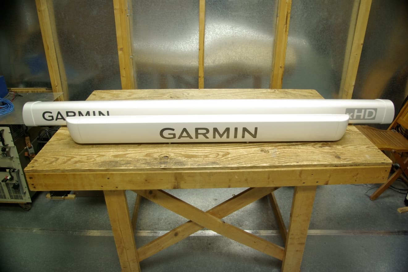
Click to zoom
Application Details
- Equipment Class
- MRD - Marine Radar
- Date of Grant
- Oct 28, 2010
- Application Purpose
- Original Equipment
- Date of Application
- Oct 28, 2010
- Equipment Note
- MARINE RADAR TRANSMITTER
- Frequency Range
- 9300.00000000 - 9500.00000000
- Company
- Garmin International Inc
- Country
- United States
Documents & Files
Document Text
Text extracted from the exhibit documents filed with the FCC. Open a document above to read the original.
Users Manual
GMR ™ 400/600/1200 xHD Radar Installation Instructions Properly install your GMR 400/600/1200 xHD radar according to the following instructions. If you experience difficulty installing the chartplotter, seek the assistance of a professional installer, or contact Garmin ® Product Support. Before installing your GMR 400/600/1200 xHD radar, confirm that the package contains the items listed on the box. If any parts are missing, contact your Garmin dealer immediately. WarnInG: Always wear safety goggles, ear protection, and a dust mask when drilling, cutting, or sanding. WarnInG: The selected radar mounting location must be able to hold the weight of the radar and withstand any inertial forces. WarnInG: The radar transmits electromagnetic energy. It is important that the radar is turned off or the DC power input is disconnected when personnel are required to come close to the radar to perform work on the radar assembly or associated equipment. Electromagnetic energy is harmful. CaUTIOn: When the radar is transmitting, do not look directly at the antenna at close range, because the eyes are the most sensitive part of the body to electromagnetic energy. nOTICe: When drilling or cutting, always check the opposite side of the drilling or cutting surface. Product Registration Help us better support you by completing our online registration today. Go to http://my.garmin.com. Keep the original sales receipt, or a photocopy, in a safe place. Contact Garmin Contact Garmin Product Support if you have any questions while installing your GMR 400/600/1200 xHD radar. In the USA, go to www.garmin.com/support, or contact Garmin USA by phone at (913) 397.8200 or (800) 800.1020. In the UK, contact Garmin (Europe) Ltd. by phone at 0808 2380000. In Europe, go to www.garmin.com/support and click Contact Support for in-country support information, or contact Garmin (Europe) Ltd. by phone at +44 (0) 870.8501241. Needed Tools For Installing the Radar: • #2 Phillips screwdriver • 5 mm Allen wrench • Drill and drill bits • Wrench and socket set For Installing the Optional Field-Installable RJ-45 Network Connector: • Knife • Pliers • 15 mm wrench • AMP modular-plug hand tool and die set or compatible equivalent October 2010 190-01266-02 Rev. A Printed in Taiwan 2 GMR 400/600/1200 xHD Installation Instructions Selecting a Location When selecting a location to install the GMR 400/600/1200 xHD radar, consider the following: • An ideal mounting location is high above the keel line of the ship with a minimal part of the structure or rigging blocking the radar beam. Obstructions in the path of the radar beam may cause blind and shadow sectors, or generate false echoes. The higher the installation position, the farther the radar can detect targets. • Avoid mounting on the same level as smoke stacks, horizontal spreaders, or crosstrees on a mast. • Do not install the radar near heat sources where it may be exposed to smoke or hot air from smoke stacks or heat from lights. • The mounting surface or platform should be sturdy enough to support the weight of the radar and any inertial forces, as flat as possible, and parallel with the water line. • Garmin recommends mounting the radar out of range of personnel (vertical beam width above head height). When properly installed and operated, the use of this radar conforms to the requirements of ANSI/IEEE C95.1-1992 Standard for Safety Levels with Respect to Human Exposure to Radio Frequency Electromagnetic Fields. IEC 60936-1 clause 3-27.1 states maximum distances from the antenna at which Radio Frequency (RF) levels can be expected. ◦ GMR 404 xHD (100W/m squared = 55 in. [1.4 m]) (10W/m squared = 178 in. [4.5 m]) ◦ GMR 406 xHD (100W/m squared = 65 in. [1.7 m]) (10W/m squared = 200 in. [5.1 m]) ◦ GMR 604 xHD (100W/m squared = 67 in. [1.7 m]) (10W/m squared = 217 in. [5.5 m]) ◦ GMR 606 xHD (100W/m squared = 79 in. [2 m]) (10W/m squared = 244 in. [6.2 m]) ◦ GMR 1204 xHD (100W/m squared = 99 in. [2.5 m]) (10W/m squared = 307 in. [7.8 m]) ◦ GMR 1206 xHD (100W/m squared = 111 in. [2.8 m]) (10W/m squared = 343 in. [8.7 m]) CaUTIOn: When the radar is transmitting, do not look directly at the antenna at close range (the eyes are the most sensitive part of the body to electromagnetic energy). • A compass safe distance must be maintained between the compass and the radar. The compass safe distance is measured from the center point of the compass to the nearest point on the radar. ◦ Standard compass = 35 7 / 16 in. (90 cm) ◦ Standby Steering and Emergency compasses = 31 1 / 2 in. (80 cm) • Mount other electronics and cables more than 7 ft. (2 m) from the path of a radar beam. A radar beam can spread 25° vertically above and below the radiating element of the radar. For vessels with higher bow angles at cruise speed, you can lower the angle so that the beam points slightly downward to the waterline while at rest. Shims may be used as necessary. 12.5° 12.5° • Install the radar away from antennas or other electronics. GPS antennas should be located above or below the radar beam path of the radar. Mount at least 3 ft. (1 m) from any equipment transmitting or cables carrying radio signals, such as VHF radios, cables, and antennas. In the case of SSB radios, the distance should be increased to 7 ft. (2 m). GMR 400/600/1200 xHD Installation Instructions 3 Installing the Mounting Studs and Seals 1. Remove the hatch on the front of pedestal by loosening the screw and lifting the hatch off of the hinges as shown in Figure 1. 2. Apply the included anti-seize compound to the threads of the four M10 x 71 mounting studs. 3. Use a 5 mm Allen wrench to install the M10 x 71 mounting studs (Figure 2) in the pedestal matching the hole pattern that was selected. Tighten the mounting studs until they bottom out in the pedestal. Do not overtighten the studs to avoid damaging the pedestal. The mounting studs have a thread-locking patch applied at the factory. 4. Install the seals onto the pedestal (Figure 3). Figure …
Text truncated - open the document above for the full version.
Cover Letter(s)
October 26, 2010 Timco Engineering Inc. 849 NW State Road 45 Newberry, FL 32669 Applicant: Garmin International, Inc. 1200 East 151st Street Olathe, KS 66062 Re: Confidentiality for submittal information regarding FCC ID number IPH-GMR4XXHD PRODUCT: Marine Radar Transmitter operated under part 80 Dear Sirs: Garmin International, Inc. requests that the material in the Schematics, Operational Description, Block diagram, and parts list be withheld from public disclosure in accordance with Section 0.459 of the Commission’s Rules, 47 C.F.R. 0.459, following grant of the application. In support of this request, Garmin International, Inc. submits the following information. CONFIDENTIAL FILES Conf BlkDia GMR40X xHD.pdf Conf OpDes GMR40X xHD.pdf Conf Schem GMR40X xHD.pdf Conf Schem GMR40X xHD 1.pdf Conf PartList GMR40X xHD Modulator Box.pdf Conf PartList GMR40X xHD Trans_Rcvr.pdf 1. Identification of the specific information for which confidential treatment is sought: The materials set forth in the Operational Description, block diagram, parts list, and Schematics, which are segregated, from the non-confidential exhibits of the application, are those for which confidentiality is sought. 2. Identification of the Commission proceeding in which the information was submitted or a description of the circumstances giving rise to the submission: The proceeding is that involving the application for equipment authorization (certification) under FCC ID No: IPH-GMR4XXHD 3. Explanation of the degree to which the information is commercial or financial, or contains a trade secret or is privileged: This material includes a detailed theory of operation, circuit diagrams, and schematic. As such, this material is treated as highly confidential business information. ROGERS LABS, INC. 4405 West 259 th Terrace Louisburg, KS 66053 913 837-3214 4 5 6 7 8 4. Explana competit The mate transmitt have a va 5. Explana Disclosur engineeri would als developm 6. Identific disclosur The infor Internatio agreemen 7. Identific previous To the kn publicly numerou FCC, the this radio 8. Justifica not be av This mat relatively and manu As such, attempt t be emplo Should y Thank yo Sincerel y Scot Rog ation of the d tion: erial for whic ting equipme ariety of com ation of how re would, in ing personne so offer com ment, thereby cation of any re: rmation for w onal, Inc. an nts. cation of wh s disclosure nowledge of heretofore. us disclosure e protection s o technology ation of the p vailable for erial should y frequently, ufacturing te it is importa to use knowl oyed. you require a ou for your c y, gers degree to wh ch confident ent that is of mpeting sour w disclosure n effect, give el, who have mpetitors add y allowing c y measures which confid nd not made a hether the in of the infor f those prepa While the g s in industry sought is nar y. period duri public dis c not be discl , disclosure o echniques th ant that the d ledge of the any further in consideration hich the inf tiality is sou ffered on a h rces. of the info r away the fru e designed th ditional unwa competitors a taken by th dential treatm available to nformation rmation to t aring this app eneral theory y and standar rrowly draw ng which th closure: osed for at l of the design hat could hav design not be design to co nformation, p n in this mat formation co ught is emplo ighly compe rmation cou uits of the la he equipmen arranted insi an advantage he submittin ment is soug third parties is available third parties plication, the y of operatio rds groups a wn and pertai he submittin east 25 year n information ve an adverse e made avail ompromise th please conta tter. oncerns a se oyed in the d etitive basis. uld result in abors of Garm nt and the ma ight into the e, not availab ng party to p ght is kept co s except purs to the publ s: e information on of this eq s well as in r ns to certain ng party ass rs. While im n would lead e competitiv lable to unau he applicatio act the under ervice that i design and m Customers substantial min Internat anufacturing state of the ble to Garmi prevent una onfidential b suant to non- lic and the e n has not be quipment has rule making n specific im serts that th mprovements d to insights ve effect for m uthorized per ons for which rsigned. is subject to manufacture o for this equ l competitiv tional, Inc.’s g process. D product in Internatio authorized by Garmin -disclosure extent of any en disclosed s been the su proceedings mplementation he material s in design ar into both de many years rsons who m h the equipm o of this uipment ve harm: s Disclosure onal, Inc. y d ubject of s of the ns of should re made esign to come. might ment will
External Photos
Rogers Labs, Inc. Garmin International, Inc. SN: 21W000005 4405 West 259 th Terrace Model: GMR40X xHD FCC ID#: IPH-GMR4XXHD Louisburg, KS 66053 Test #:101004 IC: 1792A-GMR4XXHD Phone/Fax: (913) 837-3214 Test to: FCC Parts 2 and 80, RSS-138 Date: October 16, 2010 Revision 1 File: ExtPho GMR40X xHD Page 1 of 3 External photographs of equipment under test Rogers Labs, Inc. Garmin International, Inc. SN: 21W000005 4405 West 259 th Terrace Model: GMR40X xHD FCC ID#: IPH-GMR4XXHD Louisburg, KS 66053 Test #:101004 IC: 1792A-GMR4XXHD Phone/Fax: (913) 837-3214 Test to: FCC Parts 2 and 80, RSS-138 Date: October 16, 2010 Revision 1 File: ExtPho GMR40X xHD Page 2 of 3 Antenna Options (4 and 6 foot) Rogers Labs, Inc. Garmin International, Inc. SN: 21W000005 4405 West 259 th Terrace Model: GMR40X xHD FCC ID#: IPH-GMR4XXHD Louisburg, KS 66053 Test #:101004 IC: 1792A-GMR4XXHD Phone/Fax: (913) 837-3214 Test to: FCC Parts 2 and 80, RSS-138 Date: October 16, 2010 Revision 1 File: ExtPho GMR40X xHD Page 3 of 3
ID Label/Location Info
Rogers Labs, Inc. Garmin International, Inc. SN: 21W000005 4405 West 259 th Terrace Model: GMR40X xHD FCC ID#: IPH-GMR4XXHD Louisburg, KS 66053 Test #:101004 IC: 1792A-GMR4XXHD Phone/Fax: (913) 837-3214 Test to: FCC Parts 2 and 80, RSS-138 Date: October 16, 2010 Revision 1 File: LabelSmpl GMR40X xHD Page 1 of 1 FCC ID label and location Label Placement and I/O connections Label
Internal Photos
Internal Modulator Internal Modulator Fan Internal GMR40xXHD w/Modulator Out Modulator Open Motor Board Back Motor Board Front Magnetron Photo Modulator Installed Internal GMR40xXHD Left side Internal Motor Installed Internal GMR40xXHD Internal View Full Unit 6’ xHD Antenna
RF Exposure Info
Rogers Labs, Inc. Garmin International, Inc. SN: 21W000005 4405 West 259 th Terrace Model: GMR40X xHD FCC ID#: IPH-GMR4XXHD Louisburg, KS 66053 Test #:101004 IC: 1792A-GMR4XXHD Phone/Fax: (913) 837-3214 Test to: FCC Parts 2 and 80, RSS-138 Date: October 16, 2010 Revision 1 File: RFExp GMR40X xHD Page 1 of 1
Test Report
NVLAP Lab Code 200087-0 Rogers Labs, Inc. Garmin International, Inc. FCC ID#: IPH-GMR4XXHD 4405 West 259 th Terrace Model: GMR40X xHD IC: 1792A-GMR4XXHD Louisburg, KS 66053 Test #: 101004 SN: 21W000005 Phone/Fax: (913) 837-3214 Test to: FCC Parts 2, 15, and 80, RSS-138 Date: October 28, 2010 Revision 2 File: GMR40X xHD TstRpt r2 101004 Page 1 of 31 Test Report for FCC And Industry Canada Grant of Certification Applications Model: GMR40X xHD FCC ID: IPH-GMR4XXHD IC: 1792A-GMR4XXHD Marine Radar Equipment FOR GARMIN INTERNATIONAL, INC. 1200 East 151st Street Olathe, KS 66062 Test Report Number: 101004 Authorized Signatory: Scot D. Rogers NVLAP Lab Code 200087-0 Rogers Labs, Inc. Garmin International, Inc. FCC ID#: IPH-GMR4XXHD 4405 West 259 th Terrace Model: GMR40X xHD IC: 1792A-GMR4XXHD Louisburg, KS 66053 Test #: 101004 SN: 21W000005 Phone/Fax: (913) 837-3214 Test to: FCC Parts 2, 15, and 80, RSS-138 Date: October 28, 2010 Revision 2 File: GMR40X xHD TstRpt r2 101004 Page 2 of 31 Test Report for Application of Certification Marine Radar Transmitter CFR47 part 80(E), RSS-138 For GARMIN INTERNATIONAL, INC. 1200 East 151st Street Olathe, KS 66062 Mr. Van Ruggles Director of Quality Assurance Model: GMR40X XHD Marine Radar Equipment operating in the Frequency Band of 9300 – 9500 MHz FCC ID: IPH-GMR4XXHD IC: 1792A-GMR4XXHD Test Date: October 4, 2010 Certifying Engineer: Scot D. Rogers Rogers Labs, Inc. 4405 West 259th Terrace Louisburg, KS 66053 Telephone/Facsimile: (913) 837-3214 This report shall not be reproduced except in full, without the written approval of the laboratory. This report must not be used by the client to claim product endorsement by NVLAP or any agency of the U.S. Government. ROGERS LABS, INC. 4405 West 259 th Terrace Louisburg, KS 66053 Phone / Fax (913) 837-3214 NVLAP Lab Code 200087-0 Rogers Labs, Inc. Garmin International, Inc. FCC ID#: IPH-GMR4XXHD 4405 West 259 th Terrace Model: GMR40X xHD IC: 1792A-GMR4XXHD Louisburg, KS 66053 Test #: 101004 SN: 21W000005 Phone/Fax: (913) 837-3214 Test to: FCC Parts 2, 15, and 80, RSS-138 Date: October 28, 2010 Revision 2 File: GMR40X xHD TstRpt r2 101004 Page 3 of 31 Table of Contents TABLE OF CONTENTS .................................................................................................... 3 FORWARD ....................................................................................................................... 5 APPLICABLE STANDARDS & TEST PROCEDURES .................................................... 5 OPINION / INTERPRETATION OF RESULTS ................................................................. 5 ENVIRONMENTAL CONDITIONS.................................................................................... 5 TEST SITE LOCATIONS .................................................................................................. 6 LIST OF TEST EQUIPMENT ............................................................................................ 6 EQUIPMENT TESTED ...................................................................................................... 7 EQUIPMENT CONFIGURATION ...................................................................................... 7 APPLICATION FOR CERTIFICATION ............................................................................. 8 RF POWER OUTPUT ....................................................................................................... 9 RF Power Output Measurements Required ........................................................................................................... 9 RF Power Output Test Arrangement...................................................................................................................... 9 Figure One Plot 4-foot antenna configuration RF power output at 10 meters distance .......................................... 12 Figure Two Plot 6-foot antenna configuration RF power output at 10 meters distance ......................................... 12 MODULATION CHARACTERISTICS ............................................................................... 13 Modulation Characteristics Measurements Required ........................................................................................... 13 Modulation Characteristics Test Arrangement ..................................................................................................... 13 Modulation Characteristics Results ........................................................................................................................ 13 OCCUPIED BANDWIDTH ................................................................................................ 13 Occupied Bandwidth Measurements Required ..................................................................................................... 13 Occupied Bandwidth Results ................................................................................................................................... 13 Figure Three Plot of analyzer screen showing 23-dB occupied bandwidth (1/8 nm) ............................................ 14 Figure Four Plot of analyzer screen showing 23-dB occupied bandwidth (72 nm) ............................................... 14 NVLAP Lab Code 200087-0 Rogers Labs, Inc. Garmin International, Inc. FCC ID#: IPH-GMR4XXHD 4405 West 259 th Terrace Model: GMR40X xHD IC: 1792A-GMR4XXHD Louisburg, KS 66053 Test #: 101004 SN: 21W000005 Phone/Fax: (913) 837-3214 Test to: FCC Parts 2, 15, and 80, RSS-138 Date: October 28, 2010 Revision 2 File: GMR40X xHD TstRpt r2 101004 Page 4 of 31 SPURIOUS EMISSIONS AT ANTENNA TERMINALS ..................................................... 15 Spurious Emission at Antenna Measurements Required ...................................................................................... 15 Spurious Emission at Antenna Test Arrangement ................................................................................................ 15 Spurious Emission a…
Text truncated - open the document above for the full version.
Test Setup Photos
Rogers Labs, Inc. Garmin International, Inc. SN: 21W000005 4405 West 259 th Terrace Model: GMR40X xHD FCC ID#: IPH-GMR4XXHD Louisburg, KS 66053 Test #:101004 IC: 1792A-GMR4XXHD Phone/Fax: (913) 837-3214 Test to: FCC Parts 2 and 80, RSS-138 Date: October 16, 2010 Revision 1 File: TSup GMR40X xHD Page 1 of 4 Test setup photographs 10-meter measurement distance Rogers Labs, Inc. Garmin International, Inc. SN: 21W000005 4405 West 259 th Terrace Model: GMR40X xHD FCC ID#: IPH-GMR4XXHD Louisburg, KS 66053 Test #:101004 IC: 1792A-GMR4XXHD Phone/Fax: (913) 837-3214 Test to: FCC Parts 2 and 80, RSS-138 Date: October 16, 2010 Revision 1 File: TSup GMR40X xHD Page 2 of 4 Rogers Labs, Inc. Garmin International, Inc. SN: 21W000005 4405 West 259 th Terrace Model: GMR40X xHD FCC ID#: IPH-GMR4XXHD Louisburg, KS 66053 Test #:101004 IC: 1792A-GMR4XXHD Phone/Fax: (913) 837-3214 Test to: FCC Parts 2 and 80, RSS-138 Date: October 16, 2010 Revision 1 File: TSup GMR40X xHD Page 3 of 4 3-meter measurement distance Rogers Labs, Inc. Garmin International, Inc. SN: 21W000005 4405 West 259 th Terrace Model: GMR40X xHD FCC ID#: IPH-GMR4XXHD Louisburg, KS 66053 Test #:101004 IC: 1792A-GMR4XXHD Phone/Fax: (913) 837-3214 Test to: FCC Parts 2 and 80, RSS-138 Date: October 16, 2010 Revision 1 File: TSup GMR40X xHD Page 4 of 4
Contact Information
Applicant
Ben Karsak(Manager, Compliance Engineering)
Test Firm
Rogers Labs, Inc.Scot Rogers
Technical Specifications
| # | Rule Parts | Frequency Range | Power Output | Emission |
|---|---|---|---|---|
| 1 | 80 | 9.30 GHz - 9.50 GHz | 4000 W | 9M46P0N |
Other Applications from Garmin International Inc
IPH-05126
Sep 09, 2026Portable Digital Transceiver
Equipment Class
NII - Unlicensed National Information Infrastructure TXIPH-A5126
Sep 09, 2026Portable Digital Transceiver
Equipment Class
NII - Unlicensed National Information Infrastructure TXIPH-04812
Sep 01, 2026Mobile Digital Transceiver
Equipment Class
DTS - Digital Transmission SystemIPH-A04825
Sep 01, 2026Marine Stereo
Equipment Class
DSS - Part 15 Spread Spectrum TransmitterIPH-B04825
Sep 01, 2026Marine Stereo
Equipment Class
DSS - Part 15 Spread Spectrum Transmitter