IUW38006FIELD DISTURBANCE SENSOR
Progress Instrument Inc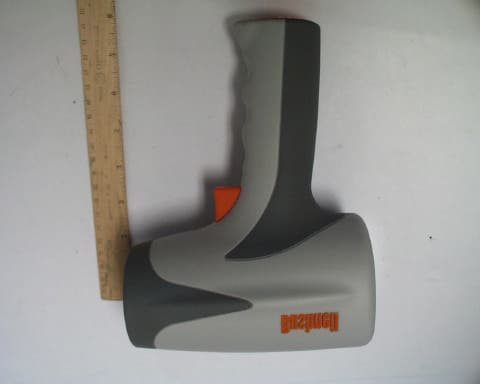
Click to zoom
Application Details
- Equipment Class
- FDS - Part 15 Field Disturbance Sensor
- Date of Grant
- May 22, 2005
- Application Purpose
- Original Equipment
- Date of Application
- May 22, 2005
- Equipment Note
- FIELD DISTURBANCE SENSOR
- Frequency Range
- 24125.00000000 - 24125.00000000
- Company
- Progress Instrument Inc
- Country
- United States
Documents & Files
Document Text
Text extracted from the exhibit documents filed with the FCC. Open a document above to read the original.
Users Manual
INTRODUCTION Your Bushnell Speed Radar uses digital technology to provide instantaneous speed measurements to +/- One-Mile per Hour (MPH) / +/- Two Kilometer per Hour (KPH) accuracy. The Bushnell Speed Radar is a simple, point and shoot radar gun for all kinds of sports enthusiasts. The Bushnell Speed Radar measures the speed of a baseball at 10-110 MPH (16-177 KPH) from 90 feet (27 meters) away from the ball, and the speed of a racecar from 10-200 MPH (16-322 KPH) at 1,500 feet (457 meters) away. BATTERY INSTALLATION Your Bushnell Speed Radar operates on two C alkaline batteries. To install, remove the battery cover by rotating the battery cap counterclockwise. Insert both batteries positive end first and replace cap by depressing and rotating clockwise. HOW TO USE 1. Turn “ON” by pressing the button underneath the LCD display. 2. Aim at the target and depress the TRIGGER. As a quick reference to accuracy, remember to keep your targets direction of travel in a direct line with you and not perpendicular to you. 3. Turn “OFF” by pressing the button underneath the LCD Display for 3 seconds or until display shuts off. The display will read 3, 2, 1, and then power off. 4. To change unit of measure from MPH to KPH and vice versa, make sure the unit is “ON”. Next, pull the trigger and leave engaged and quickly press the button underneath the LCD display (quick presses of the button underneath the LCD display will toggle between MPH and KPH). The unit of measure will be displayed in the top right hand corner of the LCD display. When you are satisfied with the unit of measure, simply release the power and trigger buttons. NOTE: The Speed Radar gun contains an automatic battery saving shut-off feature. After 10 minutes of non-use, the speed gun will automatically shut off. If a battery symbol appears on the lower right hand corner of the display, the battery voltage is beginning to deteriorate meaning new batteries should be inserted. Remove batteries if storing long-term. TARGET SPEED ACQUISITION A target can be anything that is moving faster than 10 M.P.H. / 16 K.P.H. To acquire the speed of a target, with the speed radar powered on, aim at the target and depress the TRIGGER. An icon will appear in the upper right corner of the LCD display. This indicates the Doppler Radar is functioning. The radar will continue to be active searching for speed until the trigger is released. Upon release of the trigger, the fastest speed captured within that series will automatically be displayed. The speed of the target will appear on the LCD display in MPH or KPH. There are certain mathematical properties of Doppler Radar that affect the accuracy of your Bushnell Speed Radar gun. Please read COSINE AFFECT ON TARGET VELOCITY below. As a quick reference to accuracy, remember to keep your targets direction of travel in a direct line with you, and not perpendicular. COSINE EFFECT ON TARGET The Speed Radar gun will measure the relative speed of a target as it approaches the radar gun. If the target is in a direct line (collision course) with the radar gun the measured speed will be exact. As the angle of incidence increases, if you move either right or left of this direct line, the accuracy will decrease. The measured speed will decrease as you move off this centerline. This phenomenon is called the Cosine Effect. It is called this because the measured speed is directly related to the cosine of the angle between the Radar gun and the target’s direction of travel. SPECIFICATIONS Speed Performance: Ball: 10-110 MPH from 90 Feet / 16-177 KPH from 27 Meters Car: 10-200 MPH from 1,500 Feet / 16-322 KPH from 457 Meters Accuracy: +/- One MPH / +/- Two KPH Battery Type: C (2) Operating Time: Up to 20 hours Operating Temperature Range: 32-104 F / 0-40 C NOTE: This equipment has been tested and found to comply with the limits for a Class B digital device, pursuant to part 15 of the FCC Rules. These limits are designed to provide reasonable protection against harmful interference in a residential installation. This equipment generates uses and can radiate radio frequency energy and, if not installed and used in accordance with the instructions, may cause harmful interference to radio communications. However, there is no guarantee that interference will not occur in a particular installation. If this equipment does cause harmful interference to radio or television reception, which can be determined by turning the equipment off and on, the user is encouraged to try to correct the interference by one or more of the following measures: • Reorient or relocate the receiving antenna. • Increase the separation between the equipment and receiver. • Connect the equipment into an outlet on a circuit different from that to which the receiver is connected. • Consult the dealer or an experienced radio/TV technician for help. INFORMATION TO THE USER Changes or modifications to the Bushnell Speed Radar Gun, instruction manual or printed materials, not expressly approved by Bushnell for compliance could void the user’s authority to operate the equipment. Congratulations on the purchase of your Bushnell ® Speed Radar Gun. This is a precision speed radar instrument designed to provide many years of enjoyment. These instructions will help you achieve optimum performance by explaining the adjustments and features as well as how to care for this precise speed measuring instrument. To ensure optimal performance and longevity, please read these instructions before using your speed radar. SPEED RADAR GUN Model #: 10-1900, 1911,1925 Lit. #: 98-0593/0505 WARRANTY / REPAIR — TWO YEAR LIMITED WARRANTY Your Bushnell® product is warranted to be free of defects in materials and workmanship for two years after the date of purchase. In the event of a defect under this warranty, we will, at our option, repair or replace the product, provided that you return the product postage prepaid. This warranty does not cover damages caused by misuse, improper handling, …
Text truncated - open the document above for the full version.
Block Diagram
ROGERS LABS, INC. Progress Instruments, Inc. 4405 W. 259th Terrace MODEL: Velocity Louisburg, KS 66053 Test #: 050405 FCC ID#: IUW 38006 Phone/Fax: (913) 837-3214 Test to: FCC Parts 2 and 15C Page 1 of 1 Velocity BlkDia.doc 5/18/2005 Block Diagram for Velocity.
Cover Letter(s)
February 18, 2003 Timco Engineering Inc. 849 NW State Road 45 Newberry, FL 32669 Office of Engineering and Technology Federal Communications Commission Columbia, MD 21046 Applicant: Progress Instruments, Inc. 807 Northwest Commerce Drive Lee’s Summit, MO 64086 Re: Confidentiality for submittal information regarding FCC ID number IUW38006 PRODUCT: Field Disturbance Sensor operating under part 15.245. Dear Sirs: Progress Instruments, Inc. requests that the material in the Parts List, , Schematics, block diagram, and Operational Description be withheld from public disclosure in accordance with Section 0.459 of the Commissions Rules, 47 C.F.R. 0.459 (1998), following grant of the application. In support of this request, Progress Instruments, Inc. submits the following: 1. Identification of the specific information for which confidential treatment is sought: The materials set fourth in the Operational Description, Parts List, block diagram, and Schematics, which are segregated from the non-confidential exhibits of the application, are those for which confidentiality is sought. 2. Identification of the Commission proceeding in which the information was submitted or a description of the circumstances giving rise to the submission: The proceeding is that involving the application for equipment authorization (certification) under FCC ID No: IUW38006 3. Explanation of the degree to which the information is commercial or financial, or contains a trade secret or is privileged: This material includes a detailed theory of operation, circuit diagrams, (schematic diagrams) and detail Parts List. As such, this material is treated as highly confidential business information. ROGERS LABS, INC. 4405 West 259 th Terrace Louisburg, KS 66053 4. Explanation of the degree to which the information concerns a service that is subject to competition: The material for which confidentiality is sought is employed in the design and manufacture of this transmitting equipment that is offered on a highly competitive basis. Customers for this equipment have a variety of competing sources. 5. Explanation of how disclosure of the information could result in substantial competitive harm: Disclosure would, in effect, give away the fruits of the labors of Progress Instruments, Inc.’s engineering personnel, who have designed the equipment and the manufacturing process. Disclosure would also offer competitors additional unwarranted insight into the state of the product development, thereby allowing competitors an advantage, not available to Progress Instruments, Inc. 6. Identification of any measures taken by the submitting party to prevent unauthorized disclosure: The information for which confidential treatment is sought is kept confidential by Progress Instruments, Inc. and not made available to third parties except pursuant to non-disclosure agreements. 7. Identification of whether the information is available to the public and the extent of any previous disclosure of the information to third parties: To the knowledge of those preparing this application, the information has not been disclosed publicly heretofore. While the general theory of operation of this equipment has been the subject of numerous disclosures in industry and standards groups as well as in rule making proceedings of the FCC, the protection sought is narrowly drawn and pertains to certain specific implementations of this radio technology. 8. Justification of the period during which the submitting party asserts that the material should not be available for public disclosure: This material should not be disclosed for at least 25 years. While improvements in design are made relatively frequently, disclosure of the design information would lead to insights into both design and manufacturing techniques that could have an adverse competitive effect for many years to come. This equipment is designed for commercial, industrial, and governmental applications. As such, unlike most consumer equipment, this equipment could be used for more than a decade in some cases. As such, it is important that the design not be made available to unauthorized persons who might attempt to use knowledge of the design to compromise the applications for which the equipment will be employed. Should you require any further information, please contact the undersigned. Thank you for your consideration in this matter. Sincerely, Scot Rogers
External Photos
ROGERS LABS, INC. Progress Instruments, Inc. 4405 W. 259th Terrace MODEL: Velocity IC:5380A-38006 Louisburg, KS 66053 Test #: 050405 FCCID#: IUW38006 Phone/Fax: (913) 837-3214 Test to: FCC Parts 2 and 15c Page 1 of 1 Velocity Photos.doc 5/19/2005 External photographs of equipment under test.
Internal Photos
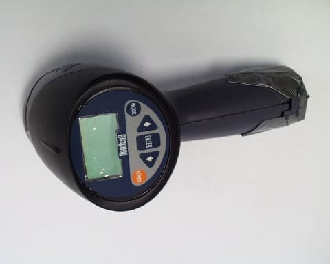
ROGERS LABS, INC. Progress Instruments, Inc. 4405 W. 259th Terrace MODEL: Velocity `IC:5380A-38006 Louisburg, KS 66053 Test #: 050405 FCCID#: IUW38006 Phone/Fax: (913) 837-3214 Test to: FCC Parts 2 and 15c Page 1 of 3 Velocity IntPho.doc 5/19/2005 Internal photographs of equipment under test. ROGERS LABS, INC. Progress Instruments, Inc. 4405 W. 259th Terrace MODEL: Velocity `IC:5380A-38006 Louisburg, KS 66053 Test #: 050405 FCCID#: IUW38006 Phone/Fax: (913) 837-3214 Test to: FCC Parts 2 and 15c Page 2 of 3 Velocity IntPho.doc 5/19/2005 ROGERS LABS, INC. Progress Instruments, Inc. 4405 W. 259th Terrace MODEL: Velocity `IC:5380A-38006 Louisburg, KS 66053 Test #: 050405 FCCID#: IUW38006 Phone/Fax: (913) 837-3214 Test to: FCC Parts 2 and 15c Page 3 of 3 Velocity IntPho.doc 5/19/2005
Schematics
5 5 4 4 3 3 2 2 1 1 DD CC BB AA Doppler 3.3V 5V Title SizeDocument NumberRev Date:Sheet of PROGRESS INSTRUMENTS INC. 807 NW Commerce Drive Lee's Summit, Mo 64086 CONFIDENTIAL: This document is Confidential and sole property of Progress Instruments, Inc. Do not duplicate, distribute or otherwise disclose to third parties. 38005-032-02 Rev C PRE-AMP A 11Wednesday, April 13, 2005 0805 C3 330p C1.1u Q2 MMBT5087L 3 1 2 R6 330 C4 100uF 6.3V TantJ2 Solder pads R8 2.2k R7100K J1 Solder pads R3 330k J3 HEADER 4 1 2 3 4 Q1 MMBT5088L 3 1 2 S U1 Rf Mod 1 3 2 R2 1.8K R4220K R1 100K C2 1u C5 4.7uf 10V Tant R9 47 R5 100K
Test Report
APPLICATION SUBMITTAL FOR GRANT OF CERTIFICATION REPORT FOR MODEL: Velocity 24,125 MHz Transmitter Field Disturbance Monitor FOR PROGRESS INSTRUMENTS, INC. 807 Northwest Commerce Drive Lee’s Summit, Missouri 64081 TEST REPORT For APPLICATION of CERTIFICATION For PROGRESS INSTRUMENTS, INC. 807 Northwest Commerce Drive Lee’s Summit, Missouri 64081 MODEL: VELOCITY Field Disturbance Monitor Frequency 24.125 GHz FCC ID: IUW38006 IC: 5380A-38006 Test Date: April 5, 2005 Certification Date: April 5, 2005 Certifying Engineer: Scot D. Rogers ROGERS LABS, INC. 4405 West 259 th Terrace Louisburg, KS 66053 Phone: (913) 837-3214 FAX: (913) 837-3214 This report shall not be reproduced except in full, without the written approval of the laboratory. This report must not be used by the client to claim product endorsement by NVLAP or any agency of the U.S. Government. ROGERS LABS, INC. 4405 West 259 th Terrace Louisburg, KS 66053 Phone / Fax (913) 837-3214 NVLAP Accredited Laboratory NVLAP Lab Code: 200087-0 ROGERS LABS, INC. Progress Instruments, Inc. 4405 W. 259th Terrace MODEL: Velocity IC: 5380A-38006 Louisburg, KS 66053 Test #: 050405 FCCID#: IUW38006 Phone/Fax: (913) 837-3214 Test to: FCC Parts 2 and 15c Page 2 of 2 certification\Progress Velocity.doc 5/19/2005 TABLE OF CONTENTS TABLE OF CONTENTS..................................................................................................2 FORWARD:.....................................................................................................................3 1) APPLICABLE STANDARDS & TEST PROCEDURES...........................................3 2.1033(b) Application for Certification.......................................................................................................4 2) EQUIPMENT TESTED.............................................................................................5 3) EQUIPMENT FUNCTION AND TESTING PROCEDURES.....................................5 4) EQUIPMENT AND CABLE CONFIGURATIONS....................................................5 Conducted Emission Test Procedure...........................................................................................................5 Radiated Emission Test Procedure..............................................................................................................6 5) LIST OF TEST EQUIPMENT...................................................................................6 6) UNITS OF MEASUREMENTS.................................................................................7 7) TEST SITE LOCATIONS.........................................................................................7 8) SUBPART B – UNINTENTIONAL RADIATORS.....................................................7 Conducted EMI............................................................................................................................................7 Radiated EMI...............................................................................................................................................8 Data: EUT and System Radiated Emissions (6 Highest):............................................................................10 Summary of Results for Conducted Emissions:...........................................................................................10 Summary of Results for Radiated Emissions:..............................................................................................10 Statement of Modifications:........................................................................................................................10 9) SUBPART C - INTENTIONAL RADIATORS.........................................................11 15.203 Antenna Requirements...................................................................................................................11 Restricted Bands of Operation Per 15.205................................................................................................11 Data 15.205:...............................................................................................................................................11 15.209 Radiated Emissions Limits; General Requirements......................................................................12 Radiated EMI.............................................................................................................................................12 Data 15.209:...............................................................................................................................................17 Data: EUT and System Radiated Emissions (6 Highest):............................................................................17 Summary of Results for Radiated Emissions:..............................................................................................17 15.245 Operation in the Band 24,075-24,175 MHz...................................................................................18 Radiated Emissions of Intentional Radiator:...............................................................................................21 Statement of Modifications:........................................................................................................................21 NVLAP Accredited Laboratory NVLAP Lab Code: 200087-0 ROGERS LABS, INC. Progress Instruments, Inc. 4405 W. 259th Terrace MODEL: Velocity IC: 5380A-38006 Louisburg, KS 66053 Test #: 050405 FCCID#: IUW38006 Phone/Fax: (913) 837-3214 Test to: FCC Parts 2 and 15c Page 3 of 3 certification\Progress Velocity.doc 5/19/2005 FORWARD: The following is submitted for consideration in obtaining a Grant of Certification for low power intentional radiators operated under CFR 47, paragraph 15.245. Name of Manufacturer: PROGRESS INSTRUMENTS, INC. 807 Northwest Commerce Drive Lee’s Summit, Missouri 64081 Name of Distributor: Bushnell Performance Optics 9200 Cody Overland Park, KS 66214 Model: VELOCITY Speed mo…
Text truncated - open the document above for the full version.
Test Report
TEST PROCEDURE PAGE:1of 4 NUMBER: Project#: 38005-010REVISION: B DATE: 05/04/05 SUBJECT: Velocity Test Procedure 1.0EQUIPMENT LIST • PC with sound card • Enclosure for test fixture. • 2.5V ~ 4.5V, 0.5 amp power supply • Velocity CPU board • Audio interface box • 2 ribbon cable (to connect CPU board to unit under test) • RS-232 cable (to connect PC to CPU board) • Radar Gun Tester software (Version 1.10) 2.0TEST PROCEDURE 1) Set the test fixture up per the diagram below. PC Audio Interface Box Test Fixture Box CPU Board Ribbon Cable Ribbon Cable UUT CPU Audio In Test Horn Audio Out Power Supply Velocity Test Fixture System Diagram Audio Line Out Audio Line IN RS-232 Level Interface Convertor RS-232 DB-9 Cable 4 Conductor Audio Cable Power Supply: 2.5 to 4.5 Volts 500 mA TEST PROCEDURE PAGE:2of 4 NUMBER: Project#: 38005-010REVISION: B DATE: 05/04/05 SUBJECT: Velocity Test Procedure 2) Adjust “Volume Control” and “Wave” to maximum and make sure they are NOT muted. MUTE ALL OTHER VOLUME CONTROLS. 3) Start “HORN ATE” radar gun test software. Icon looks like this: 4) Type the serial number in the box and then hit the “ENTER” key to start the test (or left-click on the “TEST” button). TEST PROCEDURE PAGE:3of 4 NUMBER: Project#: 38005-010REVISION: B DATE: 05/04/05 SUBJECT: Velocity Test Procedure 5) The program will ask if alignment is OK. To align, adjust the verticle and horizontal alignment knobs to get the peak value shown on the “Result” graph. 6) After alignment is complete, hit the “ENTER” button or left-click on the “Alignment Ok?” button and the computer program will start testing the unit under test. TEST PROCEDURE PAGE:4of 4 NUMBER: Project#: 38005-010REVISION: B DATE: 05/04/05 SUBJECT: Velocity Test Procedure 7) Once the testing is complete a window will pop uo indicating whether the unit under test PASSED or FAILED. You will also see the test results on the left side of the window. Left-click on “OK” to end test. 3.0DOCUMENT CONTROL Authorized Approval: ____________________________ Revision Notes: B – 05/04/05 – Updated screen shots, added PC volume setting, and test fixture setup. A – 02/18/05 - New document.
Test Setup Photos
ROGERS LABS, INC. Progress Instruments, Inc. 4405 W. 259th Terrace MODEL: Velocity IC:5380A-38006 Louisburg, KS 66053 Test #: 050405 FCCID#: IUW38006 Phone/Fax: (913) 837-3214 Test to: FCC Parts 2 and 15c Page 1 of 2 Velcoity TstPhot.doc 5/19/2005 Test setup photographs EUT at 3 meters distance. ROGERS LABS, INC. Progress Instruments, Inc. 4405 W. 259th Terrace MODEL: Velocity IC:5380A-38006 Louisburg, KS 66053 Test #: 050405 FCCID#: IUW38006 Phone/Fax: (913) 837-3214 Test to: FCC Parts 2 and 15c Page 2 of 2 Velcoity TstPhot.doc 5/19/2005 Test setup photographs EUT at 10 meters distance.
Contact Information
Applicant
Jason Troxel
816-524-4442Fax: 816-246-4556
Test Firm
Rogers Labs, Inc.Scot Rogers
Technical Specifications
| # | Rule Parts | Frequency Range | Power Output |
|---|---|---|---|
| 1 | 15.245 | 24.13 GHz - 24.13 GHz | - |
Other Applications from Progress Instrument Inc
IUWSPEEDSTER
Apr 25, 2001Field Disturbance Sensor
Equipment Class
FDS - Part 15 Field Disturbance SensorIUWRC97TX
Apr 27, 1998DSC - Part 15 Security/Remote Control Transmitter
Equipment Class
DSC - Part 15 Security/Remote Control TransmitterIUWRC97RX
Apr 08, 1998Tennis Tutor System Receiver
Equipment Class
CRR - Superregenerative ReceiverIUWRC90TX
Jul 31, 1991RC Golf Cart Transmitter
Equipment Class
DXX - Part 15 Low Power Communication Device TransmitterIUWRC90RX
Jul 29, 1991CYY - Communications Receiver used w/Pt 15 Transmitter
Equipment Class
CYY - Communications Receiver used w/Pt 15 Transmitter