IVQCCBAS900MHz Spread Spectrum Transceiver
Kustom Signals Inc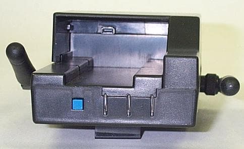
Click to zoom
Application Details
- Equipment Class
- DTS - Digital Transmission System
- Date of Grant
- Feb 18, 2007
- Application Purpose
- Original Equipment
- Date of Application
- Feb 18, 2007
- Equipment Note
- 900MHz Spread Spectrum Transceiver
- Frequency Range
- 905.00000000 - 925.00000000
- Company
- Kustom Signals Inc
- Country
- United States
Documents & Files
Document Text
Text extracted from the exhibit documents filed with the FCC. Open a document above to read the original.
Users Manual
006-0799-00 Rev 1 1 Digital Wireless Audio DSS Operating Instructions The Digital Wireless Audio DSS system is a digital frequency-agile radio designed to achieve excellent audio recording for the various Eyewitness Video systems. Transceiver Setup The Digital Wireless Audio DSS transceiver can be worn on a duty belt using the supplied pouch, or without the pouch, it can be worn/attached to an epaulet using the integrated clip. The epaulet clip remains on the transceiver even if the pouch is used – it will fit easily within the pouch. Base Station Setup The base station should be mounted according to the installation instructions (007-0798-00) found in the base station installation kit. You will need to attach the two antennas, then mount and connect the cable. For best reception, the antennas should be perpendicular to the ground. Operation Place the Transceiver (Mic) unit in the Base Unit (Base). This will “sync” the two devices. This sync will remain until the Mic is placed in a different Base or until a new Mic is placed in the Base. The last synchronization performed will override all earlier syncs. Under normal conditions, leaving the Mic in the Base will also charge the Mic, but there is no other need to place the Mic into the Base. After “syncing” is complete, the operation is very simple. The transceiver can be used with or without the supplied mic cord. There is an internal mic on the transceiver that will be used if you do not use the cord, or if the cord becomes damaged. For best results, we recommend you use the cord. When you plug it in, route the cord downward as shown, so the strap will hold the plug securely in place. 2 The Mic has a blue slide switch that is used to either 1) activate the audio system and start the video recording, or 2) to mute the audio while in the record mode. When audio is activated, you will feel a short “buzz” from the internal vibrator motor, and the LED’s will change to indicate the active mode (see LED legend below). To mute the audio, slide the switch again – this will result in two short buzzes from the internal vibrator. When you stop a Recording by pressing the Stop button on the Control Center, the Digital Wireless Audio will automatically return to the standby mode. REMOTE TRANSCEIVER LED INDICATORS LED 1 (closest to switch) LED 2 (middle) LED 3 (closest to logo) Vibrator Status OFF OFF OFF N/A Power Switch OFF RED GREEN BLUE N/A Pwr on, unit in Standby GREEN GREEN BLUE 1 Long System active, Audio recording RED GREEN BLUE 2 Short Standby or Muted RED RED BLUE N/A No Comm with Base Station OFF OFF BLUE N/A Battery Saver Mode** Normal State Normal State Slow Blink BLUE N/A Battery is low recharging required. Blink GREEN OFF OFF N/A Charging Battery GREEN OFF OFF N/A Charge Complete Flashing RED OFF OFF N/A Charge Fault ** Battery Saver Mode is entered when the Remote has lost communication with the Base for 10 or more minutes. This is to conserve battery life when an Officer is out of range for an extended amount of time. Pressing the slide switch will exit this mode or the remote will exit it automatically when the Base Station signal is received. BASE STATION LED INDICATORS LED 1 LED 2 LED 3 Status N/A N/A BLUE Power is supplied to Base unit RED GREEN BLUE Remote is in Standby or Mute GREEN GREEN BLUE Remote Active and Audio is being recorded N/A Red then Flash GREEN then Solid GREEN BLUE Remote is in Base Station and “Association” is Complete 3 Kustom Signals Inc. FCC ID: IVQCCRMT Model No. CCDSS-REM Tested To Comply with FCC Standards This device complies with Part 15 of the FCC Rules. Operation is subject to the following two conditions: (1) This device may not cause harmful interference, and (2) this device must accept any interference received, including interference that may cause undesired operation. Kustom Signals Inc. FCC ID: IVQCCBAS Model No. CCDSS-BAS Tested To Comply with FCC Standards This device complies with Part 15 of the FCC Rules. Operation is subject to the following two conditions: (1) This device may not cause harmful interference, and (2) this device must accept any interference received, including interference that may cause undesired operation. Changes not expressly approved by Kustom Signals voids the user's authority to operate the equipment. This product complies with FCC radiation exposure limits set forth for an uncontrolled environment.
Cover Letter(s)
THE EMC COMPLIANCE CENTER 12 East Devonwood SOLVING A WAVE OF EMI COMPLIANCE PROBLEMS Romeoville, IL 60446 February 15, 2007 Tel: (815) 293-0772 Page 1 of 1 Fax: (815) 293-0820 Federal Communications Commission RP-5603L Authorization and Evaluation Division 7435 Oakland Mills Rd. Columbia, MD 21046 Fax 301-344-2050 Reference FCC ID: IVQCSSBAS IVQCSSRMT Organization: Kustom Signals. This letter is to clarify the Confidentiality request on this submittal. Permanent Confidentiality Kustom Signal. requests that the following materials be withheld from public inspection permanently under 47 C.F.R. 0.459, because they are considered confidential trade secrets and technical data which customarily would be guarded from competitors: (1) Detailed Circuit Schematics of the EUT are found in the FCC electronic attachments (2) Block Diagrams (3) Circuit Description Authorized Signature January 15, 2007 Joseph Strzelecki Senior EMC Engineer Radiometrics Midwest Corporation Authorized Agent for Kustom Signals
External Photos
Authorized Agent: Radiometrics Midwest Corporation (815) 293-0772 – [email protected] External Photographs-Base Front of EUT Rear of EUT: Authorized Agent: Radiometrics Midwest Corporation (815) 293-0772 – [email protected] Right Side of EUT: Left Side of EUT Authorized Agent: Radiometrics Midwest Corporation (815) 293-0772 – [email protected] Top of EUT Bottom of EUT
ID Label/Location Info
Authorized Agent: Radiometrics Midwest Corporation (815) 293-0772 – [email protected] ID Label/Location Base Label as placed on EUT Material: 3M 7983 3 mil silver polyester 3 mil Adhesive: Permanent acrylic adhesive 467MP
Internal Photos
Authorized Agent: Radiometrics Midwest Corporation (815) 293-0772 – [email protected] FCC ID: IVQCCBAS Internal Photographs-Base Connector board Component Side Connector Board Foil Side Authorized Agent: Radiometrics Midwest Corporation (815) 293-0772 – [email protected] EUT With Front cover removed Inside Front Cover Authorized Agent: Radiometrics Midwest Corporation (815) 293-0772 – [email protected] EUT Center Cover removed Main Board; Component side Authorized Agent: Radiometrics Midwest Corporation (815) 293-0772 – [email protected] Main Board; Foil Side
RF Exposure Info
Authorized Agent: Radiometrics Midwest Corporation (815) 293-0772 – [email protected] RF Exposure This calculation is based on the highest EIRP possible from the Remote or the Base considering maximum power and antenna gain. The following formulas were used: The highest output power of the EUT is 9.1 mW and the gain of the antenna is 0 dBi 1 MINIMUM SEPARATION DISTANCE PER OET 65 The following information provides the minimum separation distance for the EUT, as calculated from FCC OET 65 Appendix B, Table 1B “Guidelines for General Population/Uncontrolled Exposure” SMaximum AntennaMSD Freq.GP limitRF power GainEIRPEIRPd MHzmW/cm^2 dBmdBdBmwattsmeters 925 0.6166679.609.60.0091 0.0108 GP is the limit for general Population/Uncontrolled Exposure MSD is the minimum Seperation Distance Notes on above table. (S) GP limit is from OET 65 table 1B EIRP = Power in dBm + Antenna Gain in dBi MSD (Minimum Separation Distance) = ((EIRP*30)/3770*S))^0.5 NOTE: For mobile or fixed location transmitters, minimum separation distance is 20 cm, even if calculations indicate MPE distance is less The low threshold for a device operated within 2.5 cm from human body is 60/(f GHz) = 60/0.927 = 64.725 mw Since this device has a power which is lower than 64.725 mw, no SAR is required. 2 RF EVAULATION FOR RSS-102E Since the e.i.r.p. of the Product is less than 10 mW, it is exempt from routine SAR and RF exposure evaluations in accordance to Sections 2.5.1 or 2.5.2 of RSS-102e.
Test Report
Radiometrics Midwest Corporation (815) 293-0772 – www.radiomet.com Page 1 of 28 Electromagnetic Compatibility Test Report Tests Performed on a Kustom Signals, Inc. Clearcomm Transciever, Model CCDSS Radiometrics Document RP-5603 Product Detail: FCC ID: IVQCCBAS, IVQCCRMT IC: 1293B-CCBAS, 1293B-CCRMT Equipment type: 900 MHz Spread Spectrum Transmitter Test Standards: US CFR Title 47, Chapter I, FCC Part 15 Subpart C FCC Part 15 CFR Title 47: 2006 Industry Canada RSS-210, Issue 6 as required for Category I Equipment This report concerns: Original Grant for Certification FCC Part 15.247 Tests Performed For: Test Facility: Kustom Signals, Inc. 9325 Pflumm Lenexa, KS - 66215-3347 Radiometrics Midwest Corporation 12 East Devonwood Romeoville, IL 60446 Test Date(s): (Month-Day-Year) November 2, 3 and 6, 2006 Document RP-5603 Revisions: Rev. Issue Date Affected Pages Revised By 0 February 1, 2006 RADIOMETRICS MIDWEST CORPORATION - EMC Test Report Testing of the Kustom Signals, Inc., Model CCDSS, Clearcomm RP-5603 Rev. 0 Page 2 of 28 Table of Contents 1 ADMINISTRATIVE DATA ................................................................................................................... 3 2 TEST SUMMARY AND RESULTS .....................................................................................................3 2.1 RF Exposure Compliance Requirements ..................................................................................... 4 3 EQUIPMENT UNDER TEST (EUT) DETAILS .................................................................................... 4 3.1 EUT Description ........................................................................................................................... 4 3.1.1 FCC Section 15.203 & RSS-GEN Antenna Requirements .................................................... 4 4 TESTED SYSTEM DETAILS .............................................................................................................. 4 4.1 Tested System Configuration ....................................................................................................... 4 4.2 Special Accessories ..................................................................................................................... 4 5 TEST SPECIFICATIONS AND RELATED DOCUMENTS.................................................................. 5 6 RADIOMETRICS’ TEST FACILITIES .................................................................................................5 7 DEVIATIONS AND EXCLUSIONS FROM THE TEST SPECIFICATIONS......................................... 6 8 CERTIFICATION ................................................................................................................................ 6 9 TEST EQUIPMENT TABLE ................................................................................................................ 6 10 TEST SECTIONS ............................................................................................................................. 7 10.1 Occupied Bandwidth .................................................................................................................. 7 10.2 Peak Output Power .................................................................................................................. 13 10.3 Power Spectral Density ............................................................................................................ 14 10.4 Band-edge Compliance of RF Conducted Emissions .............................................................. 14 10.5 Spurious RF Conducted Emissions.......................................................................................... 17 10.6 Spurious Radiated Emissions (Restricted Band) ..................................................................... 23 10.6.1 Radiated Emissions Field Strength Sample Calculation.................................................... 24 Figure 1. Drawing of Radiated Emissions Setup .......................................................................... 25 10.6.2 Spurious Radiated Emissions Test Results (Restricted Band) .......................................... 25 Notice: This report must not be reproduced (except in full) without the written approval of Radiometrics Midwest Corporation. RADIOMETRICS MIDWEST CORPORATION - EMC Test Report Testing of the Kustom Signals, Inc., Model CCDSS, Clearcomm RP-5603 Rev. 0 Page 3 of 28 1 ADMINISTRATIVE DATA Equipment Under Test: A Kustom Signals, Inc., Clearcomm Model: CCDSS Serial Number: none This will be referred to as the EUT in this Report Date EUT Received at Radiometrics: (Month-Day-Year) Test Date(s): (Month-Day-Year) November 30, 2005 November 2, 3 and 6, 2006 Test Report Written By: Test Witnessed By: Joseph Strzelecki Senior EMC Engineer The tests were not witnessed by Kustom Signals, Inc. Radiometrics’ Personnel Responsible for Test: Test Report Approved By Joseph Strzelecki Senior EMC Engineer NARTE EMC-000877-NE Chris W. Carlson Director of Engineering NARTE EMC-000921-NE 2 TEST SUMMARY AND RESULTS The EUT (Equipment Under Test) is a Clearcomm, Model CCDSS, manufactured by Kustom Signals, Inc. The detailed test results are presented in a separate section. The following is a summary of the test results. Emissions Tests Results Environmental Phenomena Frequency Range Basic Standard Test Result RF Radiated Emissions 30-9300 MHz RSS-210 & FCC Part 15 Pass Occupied Bandwidth Test Fundamental Freq. RSS-210 & FCC Part 15 Pass Spread Spectrum Transmitter Requirements Environmental Phenomena Frequency Range FCC Section RSS-210 Section Test Result 6 dB Bandwidth Test 902-928 MHz 15.247 a A8.1 (4) Pass 20 dB Bandwidth Test 902-928 MHz 15.247 a A8.1 (4) Pass Peak Output Power 902-928 MHz 15.247 b A8.1 (1) Pass Band-edge Compliance of RF Conducted Emissions 902-928 MHz 15.247 d A8.4 (2) Pass Spurious RF Conducted Emissions 30-9300 MHz 15.247 d A8.5 Pass Spurious Radiated Emissions 30-9300 MHz 15.247 d A8.5 Pass Pow…
Text truncated - open the document above for the full version.
Test Setup Photos
Authorized Agent: Radiometrics Midwest Corporation (815) 293-0772 – [email protected] Test Setup Photographs FCC ID: IVQCCBAS Photographs of Radiated Emissions Test Setup Authorized Agent: Radiometrics Midwest Corporation (815) 293-0772 – [email protected]
Contact Information
Applicant
Maurice E Shelton(Lead Engineer)
Test Firm
Radiometrics Midwest Corp.Joseph Strzelecki
Technical Specifications
| # | Rule Parts | Frequency Range | Power Output |
|---|---|---|---|
| 1 | 15C | 905 MHz - 925 MHz | 9.00 mW |
Other Applications from Kustom Signals Inc
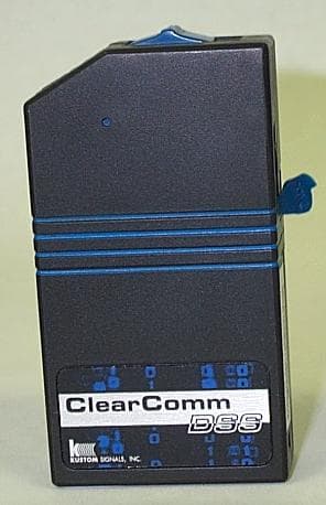
IVQCCRMT
Feb 18, 2007900 MHz Spread Spectrum Transceiver
Equipment Class
DTS - Digital Transmission System
IVQFAL-HR
Nov 19, 2006FIELD DISTURBANCE SENSOR
Equipment Class
FDS - Part 15 Field Disturbance Sensor
IVQDRU-II
Jun 13, 2006FIELD DISTURBANCE SENSOR
Equipment Class
FDS - Part 15 Field Disturbance Sensor
IVQDRU
Mar 21, 2000Speed monitoring device
Equipment Class
FDS - Part 15 Field Disturbance Sensor
IVQTAL
Mar 24, 1999TNB - Licensed Non-Broadcast Station Transmitter
Equipment Class
TNB - Licensed Non-Broadcast Station Transmitter