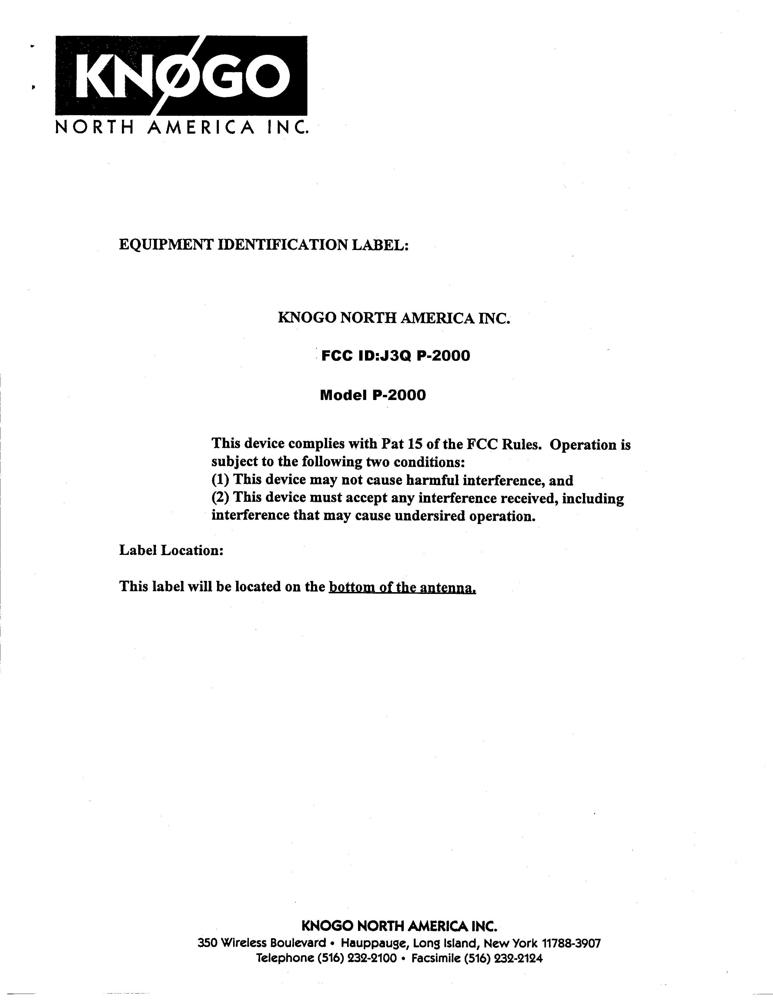
J3QP-2000
Knogo North America Inc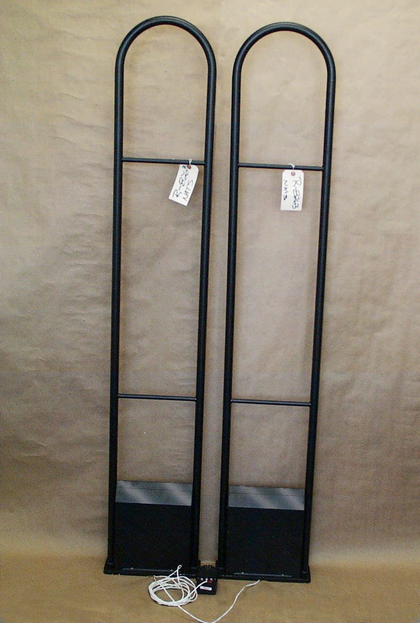
Click to zoom
Application Details
- Equipment Class
- FAP - Part 15 Anti-Pilferage Device
- Date of Grant
- May 15, 2000
- Application Purpose
- Original Equipment
- Date of Application
- Jan 10, 2000
- Frequency Range
- 7.45000000 - 8.95000000
- Company
- Knogo North America Inc
- Country
- United States
Documents & Files
Document Text
Text extracted from the exhibit documents filed with the FCC. Open a document above to read the original.
Users Manual
1 P-2000 Installation Procedure Caution Changes or modifications not expressly approved by the party responsible for compliance to the FCC rules could void the user’s authority to operate this equipment. Pre-installation requirements: 1. Pedestals must be mounted at least 2-3 feet away from all mechanical and electrical devices or large metal objects to avoid spurious resonances and noise sources. This includes doorframes, window frames, walls, beams, alarm wiring, etc. 1. All system wiring (including the AC power) must enter and exit the center of every antenna base at a 90-degree angle (down the middle at a right angle to the antenna base). If the wiring makes a turn before it enters or after it exits the base, the turn must occur at least 1 foot away from the base. 2. All system wiring must never run vertically near the antenna. Wiring should run underneath the floor or on top of the floor in electrical metallic tubing or metallic floor molding. If the wiring must run vertically, make sure it is at least 3’ away from the antenna. 3. AC power should be a 3-wire dedicated line. Connect the 18VAC from the transformer to TB4 pin 1 and pin 3 on the RV. Using the red/black 18ga. Twisted pair provided; Connect the red wire from TB4 pin 1 on the RV to TB1 pin 1 on the TX. Connect the black wire from TB 4 pin 3 on the RV to TB1 pin 3 on the TX. All wiring should be run perpendicular to the antennae. Installation: 1. Mount the RV antenna and the TX antenna so that the aisle-width is 3 feet. 2. Verify that the controls on the TX PCB are set as follows: R45Center Freq.Pre-set at factory for 8.2MHz R17Sweep WidthPre-set at factory R36Transmit LevelPre-set at factory JP1Slave terminationHI-Z JP6MSTRinstalled JP7FBR SLVnot installed JP8WRD SLVnot installed 2 S1 settings: SWITCH #FUNCTIONDEFAULT SETTING 1LINE FREQ. OFF=60HZ ON=50HZOFF 2MODULATION FREQUENCY OFF=ALTERNATE ON=STANDARD ON 3RESERVEDOFF 4RESERVEDOFF 5RESERVEDOFF 6OFF=SLAVE ON=MASTERON 7RESERVEDOFF 8RESERVEDOFF 3. Verify that the controls on the RV are set as follows: The default settings are as follows: P1 Noise Blanker5/8 CW (2 O’clock) P2 Alarm thresholdslightly less than ½ CW ( 11 O’clock) P3 Band thresholdslightly more than 1/2 CW (1 O’clock) P4 Cart InhibitFully CCW P5 Null AdjustmentPre-set at factory P6 Beeper Volume1/3 CW JP1 Input transformer CT GNDinstalled JP4 FE Gain Selectcenter position JP5 Detector Outputnot installed SW2 settings: SWITCH #FUNCTIONDEFAULT SETTING 1AUDIO TONE OFF=PULSED ON=CONTINUOUS OFF 2AUDIO TIME OFF=2 SEC ON=4 SECOFF 3LIGHT TIME OFF=2 SEC ON=4 SECOFF 4RELAY OFF=1 SEC ON=DISABLEDOFF 5RESERVEDOFF 6RESERVEDOFF 7RESERVEDOFF 8RESERVEDOFF 3 9LINE FREQ. OFF=60HZ ON=50HZOFF 10MODULATION FREQUENCY OFF=ALTERNATE ON=STANDARD ON 4. Connect a DVM set for VDC to TP4 (AGC) and TP5 (GND). Verify that the voltage is between –6VDC and +6VDC. 5. Connect a DVM set for VAC RMS to TP1 (VIDEO) and TP5 (GND) on the RV. Adjust P7 until the DVM reads 1 VRMS maximum. 6. The TP2 (DISPLAY DAC) test point is multiplexed into eight cells. In order to view this test point you must synchronize your scope to the square wave on TP3 (DISPLAY SYNC). Set the scope for (+ ) edge trigger and adjust the timebase to display only the positive portion of the square wave on TP3. Connect a second scope probe to TP2, adjust the GND reference at the bottom of the display, adjust the vertical sensitivity for .5V/div. and set the scope for CHOP. Adjust the TP2 scope input for DC couple and observe that the trace has approximately 2.5VDC offset (DAC offset). You should see four discrete traces from left to right (easier to view if you shut off the trace for the display sync.). The cells are as follows: Signal Channel Noise Channel Low band energy level High band energy level Although the Alarm threshold has been pre-set, it can be adjusted. Adjust P2 on the RV until the signal channel is approximately 0.7VDC lower than the noise channel. When the signal channel exceeds the noise channel and the high band energy level exceeds the low band energy level the alarm is triggered. 7. Set the TP3 scope input for (-) edge trigger to view the remaining four cells which are as follows: Short term averager Differential averager Beacon display Long term averager 8. Observe the short term averager on TP3 as outlined in the previous step. The synchronous energy on the short term averager should be less that 0.5Vp-p. 9. Remove all test equipment and close the antenna base covers. Verify that the system 4 is working properly with appropriate tag. 10. Demonstrate the system to the storeowner or manager and obtain signature on installation acceptance form.
Operational Description
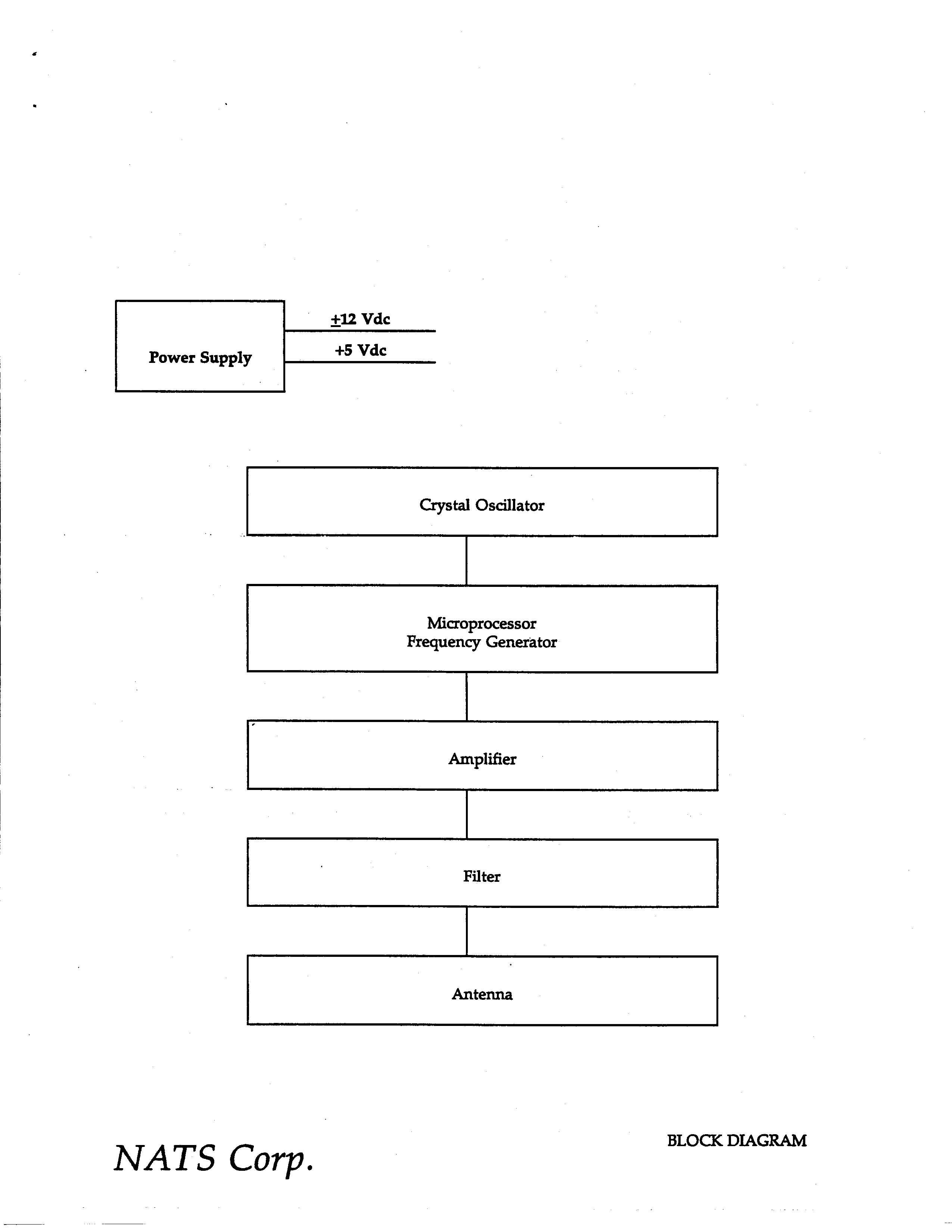
The transmitter is an analog system that sweeps from 7.45MHz to 8.95MHz. The modulation signal is sinusoidal and the frequency is 324.375Hz. The four restricted frequency bands that we sweep through are: 8.291MHz – 8.294MHz (3KHz wide) 8.362MHz – 8.366MHz (4KHz wide) 8.37625MHz – 8.38675MHz (10.5KHz wide) 8.41425MHz – 8.41475MHz (0.5KHz wide) The transmitter will spend more time in the 8.37625MHz – 8.38675MHz band because it is the widest band (10.5KHz wide). It takes 1.54143mS to sweep from 7.45MHz to 8.95MHz or to sweep from 8.95MHz to 7.45MHz (1/2 period of the modulation signal). It takes 6.74uS to sweep through the 8.37625MHz – 8.38675MHz band. Therefore, the transmitter spends 100*(6.74uS/1.54143mS) = 0.44% of the total time in this band. Section 15.205(d)(1) of your rules allow for 1%.
Test Report
November 8, 1999 North American Technical Services 30 Northport Road Sound Beach, NY 11789 Attention: Mr. Richard Lanzillotto Dear Sir: Enclosed you will find a hard copy of Retlif Test Report R-8263-1 (report of measurements) for your electronic filing which covers the Part 15, Subpart C Certification testing of the Knogo North America, 8 MHz Electronic Article Surveillance System, Model P-2000. Also enclosed you find the Conducted Emissions and the Occupied Bandwidth Data that you will need to scan. I will electronically send you the Test Report, Radiated Emissions and the Test Equipment Lists. This testing was performed in accordance with your Purchase Order Number 1099. Thank you for the opportunity to be of service to you. Should you have any questions regarding the enclosed application please feel free to contact me. Very truly yours, RETLIF TEST1NG LABORATORIES Michelle Tirado Administrative Coordinator Enc. (as stated) EXHIBIT 4 Report of Measurements Para. 2.1033(b)(6) REPORT No. R-8263-1 APPLICANT Knogo North America 350 Wireless Boulevard Hauppauge, NY 11788 MANUFACTURER Same TEST SPECIFICATION: FCC Rules and Regulations Part 15, Subpart C TEST PROCEDURE: ANSI C63.4:1992 TEST SAMP LE DESCRIP TION BRANDNAME: Knogo North America MODEL: P-2000 TYPE: Swept RF Transmitter POWER REQUIREMENTS: 18VAC (derived from 115VAC Transformer) FREQUENCY OF OPERATION: 7.45 MHz to 8.95 MHz TESTS P ERFORMED Para. 15.207(a)Conducted Emissions Para. 15.209(a)Radiated Emissions, Spurious Para. 15.223(a)Radiated Emissions, Fundamental Occupied Bandwidth REPORT OF MEASUREMENTS Applicant: Knogo North America Device:8 MHz Swept RF, Electronic Article Surveillance System FCC ID: Power Requirements: 18 VAC derived from a 115 VAC Transformer Applicable Rule Section:Part 15, Subpart C, Section 15.223 REPORT No. R-8263-1 TEST RESULTS 15.223(a)-The field strength of any emissions within the band of 1.705MHz to 10.0MHz did not exceed 100μV/M (10,000μV/M) at 30 meters (3 meters), average. The 6 dB Bandwidth of the device was found to be greater than 10% of the center frequency. 15.223(b)-The field strength of any emissions outside the 1.705 to 10 MHz band did not exceed the general radiated emissions limits of section 15.209. All signals within 10 dB of the limit at 3 meters are reported herein. Notes: Since the device operates over a range greater than 1 MHz, all testing was performed with the Swept RF Output stopped at a low and high frequency (7.52 MHz and 8.89 MHz respectively). REPORT No. R-8263-1 Exhibit 4 Report of Measurements 15.207(a) Conducted Emissions Data REPORT No. R-8263-1 Exhibit 4 Report of Measurements 15.209(a), 15.223 Radiated Emissions Data Test Method:FCC Part 15 Radiated Emissions, 9Khz to 30 Mhz paragraph 15.223 Customer:NATS (Knogo North America)Job No.R-8263-1 Test Sample: Electronic Article Surveillance Model No.:P-2000 Serial N/A Operating EUT continuously transmitting a signal at frequency specified below Technician:Dennis CortesDate:September 13, 1999 Notes: Test Distance: 10 Meters Temp:18C Humidity:25% Detector: Peak All readings were extrapolated Test Freq. Antenna Pol./Rotat ion EUT Orientat ion Meter Reading Correct ion Factor Correct ed Reading 30 Meter Equiv. Converte d Reading Limi t Mhz (V/H)/degr Degrees dBuv dB uV/m EUT continuously transmitting a 7.52 Mhz signal 7.52 V-158 315 40.3 10.5 50.8 31.7 38.5 100 EUT continuously transmitting a 8.89 Mhz signal 8.89 V-158 315 39.3 10.5 49.8 30.7 34.2 100 The EUT was scanned from 9Khz to 30 Mhz The emissions observed from the EUT do not exceed the specified limits. were more than 10dB under the specified limit Test Method:FCC Part 15 Radiated Emissions, 30 Mhz to 1 Ghz paragraph 15.223 Customer:NATS (Knogo North America)Job No.R-8263-1 Test Sample: Electronic Article Surveillance Model No.:P-2000 Serial N/A Operating EUT continuously transmitting a signal at frequency specified below Technician:Dennis CortesDate:September 13, 1999 Notes: Test Distance: 3 Meters Temp:18C Humidity:25% Detector: Quasi-Peak. Test Freq. Antenna Pol./Heigh t EUT Orientat ion Meter Reading Correction Factor Corrected Reading Converted Reading Limit Mhz (V/H)/ Degrees dBuv dB dBuv/m uV/m uV/m EUT continuously transmitting a 7.52Mhz signal 37.6 V-1.0 338 44.0 -5.5 38.5 84.1 100 45.1 V-1.0 338 28.0 -8.3 19.7 9.7 100 EUT continuously transmitting a 8.89Mhz signal 35.6 V-1.0 135 42.1 -4.5 37.6 75.9 100 44.4 V-1.0 338 47.6 -8.5 39.1 90.2 100 53.3 V-1.0 338 34.0 -10.8 23.2 14.5 100 62.2 V-1.0 338 39.0 -12.4 26.6 21.4 100 The EUT was scanned from 30 Mhz to 1 Ghz The emissions observed from the EUT do not exceed the specified limits. were more than 10dB under the specified limit Test Method:FCC Part 15 Radiated Emissions, 9 Khz to 1 Ghz paragraph 15.209 Customer:NATS (Knogo North America)Job No.R-8263-1 Test Sample: Electronic Article Surveillance Model No.:P-2000 Serial N/A OperatingEUT continuously transmitting a sweeping signal from 7.52 Mhz to Technician:Dennis CortesDate:October 15,1999 Notes:Test Distance: 3 Meters Temp: 18C Humidity: 25% Detector: Quasi-Peak Test Freq. Antenna Positio n EUT Orientati on Meter Reading Correctio n Factor Corrected Reading Converted Reading Limit Mhz V/H- Degrees dBuv dB dBuv/m uv/m uV/m .009266.7 || V| .4904.89 .49048.9 || V| 1.70514.1 1.70530 || V| 30.030 30.0100 || V| 88.0100 88.0150 || V| 216.0150 216.0200 || 246.2 V-1.5 203 33.9 -6.9 27.0 22.4 | 328.7 V-1.0 248 36.0 -4.2 31.8 38.9 | 414.0 V-1.0 203 33.8 -1.8 32.0 39.8 | 543.8 V-1.0 203 34.4 1.4 35.8 61.7 | 653.8 V-1.3 135 33.1 3.7 36.8 69.2 | || 960.0200 960.0500 || 1000.0500 The EUT was scanned from 9 Khz to 1 Ghz The emissions observed from the EUT do not exceed the specified limits. were more than 10dB under the specified limit REPORT No. R-8263-1 Exhibit 4 Report of Measurements Occupied Bandwidth Data REPORT No. R-8263-1 TEST EQUIPMENT LIST REPORT No. R-8263-1 EQUIPMENT LIST FCC 15.207 Conducted Emissions ENTypeManufacture rFre que ncy RangeMode l No.Cal Date Due D…
Text truncated - open the document above for the full version.
Contact Information
Applicant
Paula Mauro(Documentation Control)
516 232-2100Fax: 516 232-2124
Technical Contact
NATS Corp.Richard C Lanzillotto
[email protected]16317440059
30 Northport Rd · Sound Beach, New York · United States
Non-Technical Contact
Same as Item 5Richard C Lanzillotto
Test Firm
Retlif Testing LaboratoriesMichael Bozza
Technical Specifications
| # | Rule Parts | Frequency Range | Power Output |
|---|---|---|---|
| 1 | 15C | 7.45 MHz - 8.95 MHz | - |
Other Applications from Knogo North America Inc
J3QWDD
Jul 19, 2001Swept RF EAS System
Equipment Class
DXT - Part 15 Low Power Transceiver, Rx Verified
J3QT-2000
Dec 13, 2000FAP - Part 15 Anti-Pilferage Device
Equipment Class
FAP - Part 15 Anti-Pilferage DeviceJ3Q-2SRF-VD
Jan 23, 1997RF Card Reader
Equipment Class
FDS - Part 15 Field Disturbance SensorJ3Q3701
May 23, 1995Anti-Pilferage Device
Equipment Class
FDS - Part 15 Field Disturbance SensorJ3Q7201-915
Jul 22, 1992Range Finding System Transmitter
Equipment Class
DXX - Part 15 Low Power Communication Device Transmitter