J3QWDDSwept RF EAS System
Knogo North America Inc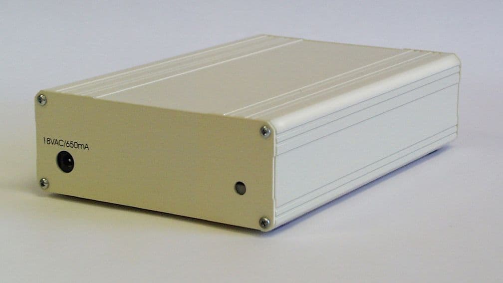
Click to zoom
Application Details
- Equipment Class
- DXT - Part 15 Low Power Transceiver, Rx Verified
- Date of Grant
- Jul 19, 2001
- Application Purpose
- Original Equipment
- Date of Application
- May 29, 2001
- Equipment Note
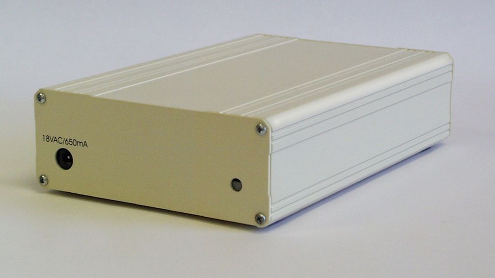
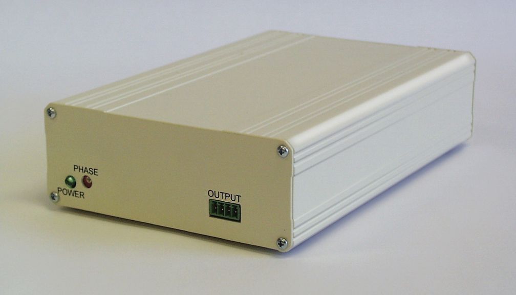
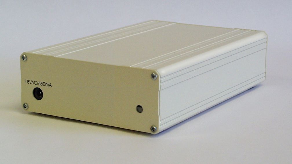
- Swept RF EAS System
- Frequency Range
- 1.80000000 - 8.90000000
- Company
- Knogo North America Inc
- Country
- United States
Documents & Files
Document Text
Text extracted from the exhibit documents filed with the FCC. Open a document above to read the original.
Users Manual
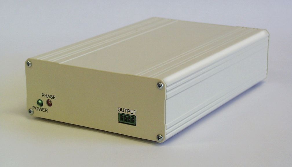
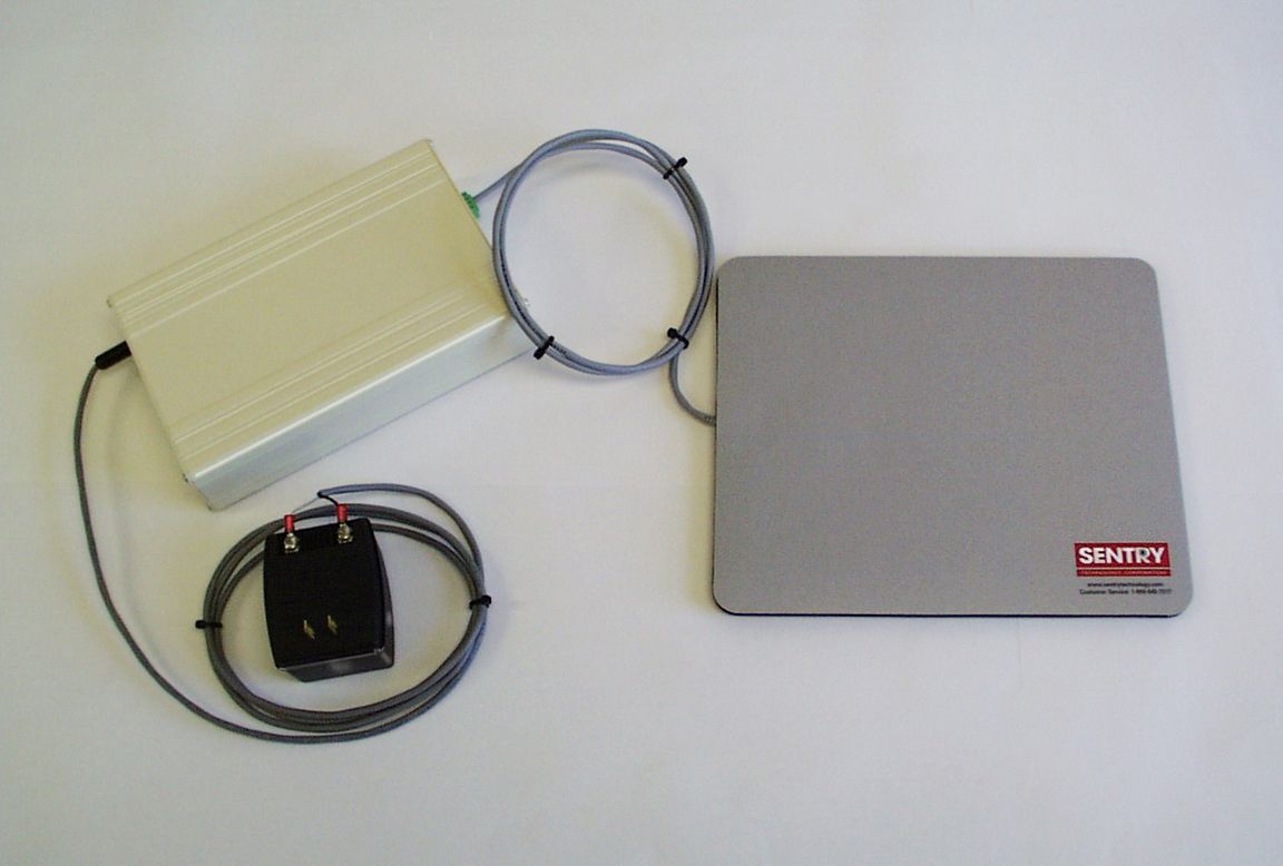
Knogo North America 2MHz Wrap Desk Deactivator Installation Procedure 1.0 System Description. The 2MHz Wrap Desk Deactivator is an accessory normally used with the P and T series RF detection systems. The P and T series detection systems provide the ability to detect small parallel LC resonant circuit tags in a zone of up to 6 feet between the receiver and transmiiter antenna. The system is normally installed at the exit doorway to the store. The Wrap Desk is normally installed at the point of sale register and detects the same tags on the merchandise at a much smaller range. Sales personnel can then be made aware of concealed tags on merchandise that is being rung-up at the register. This prevents embarrasing alarms on paying customers if they were to exit the store with tagged merchandise. The transmit signal from the system is a sequence of RF bursts at 2MHz.. This signal is amplified and low pass filtered before it is fed to the transceiver antenna loop. During the transmit burst, if a tag is placed close to the antenna it will absorb energy from the field. After each burst, there is a delay which allows the trasmitter output to decay. The receiver processes the remaining signal on the antenna which is the energy released by the tag. The signal is detected and is fed to a sample and hold circuit. If the tag has the correct signature, the alarm is sounded. 2.0 System Installation. 2.1 Unpacking and Inspection. The unit is shipped in a single box containing the following items: Main Chassis 16.5VAC wall plug-in transformer Antenna pad Installation Manual 2.2 Power Connection. The supplied 16.5VAC wall plug-in transformer has a low voltage line cord terminated with a power plug and the antenna pad with a pluggable terminal block. Simply plug the line cord and antenna pad into the chassis and the transformer into a nearby 120VAC outlet. For best performance, route the power cable directly away from the unit. Do not coil or bundle the power cable near the unit. If excess cable length is available it may be coiled or tied near the power transformer. 2.3 System Placement Proper placement of the system is important due to the effect that nearby tags and metallic objects may have on performance. Two important points govern installation: 1: Try to eliminate metallic objects under and in the immediate area surrounting the unit. 2: Tag detection below the system is equal to that above. As a general rule try to maintain at least 4” of clearance below the unit to metallic objects and approximately 5” horizontally. Small objects such as nails, screws and fittings that might be found in non- metallic counter surfaces do not present a problem and need not be considered Proximity of tags to the system is critical. Normal detection range is 12” to 18” vertically. The bin used to hold removed tags should be as far as practical from the system. A metallic container will provide a good degree of sheilding. A foil lining on a non-metallic container is also very useful. If any difficulty is encountered move the unit to a location well free of tags and metallic objects and retest. Be sure to hold the tag by the ends with the tips of your fingers, well away from the palm. 2.4 Adjustments There are no system adjusments. If 2 or more units interfere with each other, the user must select a different phase for each unit via the switch located on the front panel. There are 16 phases to choose from. 3.0 Specifications. Agency Approvals: FCC ID#: J3Q8/2MWDD Industry Canada: ETL: CETL: Power Requirements: 115VAC 60Hz 0.5A max Physical Size: Main Chassis: 8” L X 5.25” W X 2” H Power Supply: 16.5VAC, 650mA max. Weight: Complete System: 2 lbs. Operating Temperature Range: 0 to 50 degrees C Indicators: Audible Piezo beeper on Tag detect, Power LED Antenna: 9.75” L X 8.25” W X 0.375” H
Users Manual
Knogo North America 8MHz Wrap Desk Deactivator Installation Procedure 1.0 System Description. The 8MHz Wrap Desk Deactivator is an accessory normally used with the P and T series RF detection systems. The P and T series detection systems provide the ability to detect small parallel LC resonant circuit tags in a zone of up to 6 feet between the receiver and transmiiter antenna. The system is normally installed at the exit doorway to the store. The Wrap Desk is normally installed at the point of sale register and detects the same tags on the merchandise at a much smaller range. Sales personnel can then be made aware of concealed tags on merchandise that is being rung-up at the register. This prevents embarrasing alarms on paying customers if they were to exit the store with tagged merchandise. It also has the capability to deactivate small disposable tags. Deactivation is acomplished by inducing enough voltage into the tag so as to exceed the breakdown voltage of the tuning capacitor resulting in a short circuit that turns the tag off. The transmit signal from the system is a sequence of RF bursts between 7.5MHz, and 8.9MHz. This signal is amplified and low pass filtered before it is fed to the transceiver antenna loop. During the transmit burst, if a tag is placed close to the antenna it will absorb energy from the field. After each burst, there is a delay which allows the trasmitter output to decay. The receiver processes the remaining signal on the antenna which is the energy released by the tag. The signal is detected and is fed to a sample and hold circuit. If the tag has the correct signature, the alarm is sounded. 2.0 System Installation. 2.1 Unpacking and Inspection. The unit is shipped in a single box containing the following items: Main Chassis 16.5VAC wall plug-in transformer Antenna pad Installation Manual 2.2 Power Connection. The supplied 16.5VAC wall plug-in transformer has a low voltage line cord terminated with a power plug and the antenna pad with a pluggable terminal block. Simply plug the line cord and antenna pad into the chassis and the transformer into a nearby 120VAC outlet. For best performance, route the power cable directly away from the unit. Do not coil or bundle the power cable near the unit. If excess cable length is available it may be coiled or tied near the power transformer. 2.3 System Placement Proper placement of the system is important due to the effect that nearby tags and metallic objects may have on performance. Two important points govern installation: 1: Try to eliminate metallic objects under and in the immediate area surrounting the unit. 2: Tag detection below the system is equal to that above. As a general rule try to maintain at least 4” of clearance below the unit to metallic objects and approximately 5” horizontally. Small objects such as nails, screws and fittings that might be found in non- metallic counter surfaces do not present a problem and need not be considered Proximity of tags to the system is critical. Normal detection range is 12” to 18” vertically. The bin used to hold removed tags should be as far as practical from the system. A metallic container will provide a good degree of sheilding. A foil lining on a non-metallic container is also very useful. If any difficulty is encountered move the unit to a location well free of tags and metallic objects and retest. Be sure to hold the tag by the ends with the tips of your fingers, well away from the palm. 2.4 Adjustments There are no system adjusments. If 2 or more units interfere with each other, the user must select a different phase for each unit via the switch located on the front panel. There are 16 phases to choose from. 3.0 Specifications. Agency Approvals: FCC ID#: J3Q8/2MWDD Industry Canada: ETL: CETL: Power Requirements: 115VAC 60Hz 0.5A max Physical Size: Main Chassis: 8” L X 5.25” W X 2” H Power Supply: 16.5VAC, 650mA max. Weight: Complete System: 2 lbs. Operating Temperature Range: 0 to 50 degrees C Indicators: Audible Piezo beeper on Tag detect, Power LED Antenna: 9.75” L X 8.25” W X 0.375” H
Block Diagram
U21 Microprocessor U7 Direct Digital Synthesis Y2 8.000MHz Y1 40.00000MHz Transmitter 2MHz Low Pass Filter Antenna U4 Receiver U7 Amplifier U14 Sampling B1 Beeper Knogo North America 2MHz Wrap Desk Deactivator
Block Diagram
U21 Microprocessor U7 Direct Digital Synthesis Y2 8.000MHz Y1 40.00000MHz Transmitter 8.2MHz Low Pass Filter Antenna U4 Receiver U7 Amplifier U14 Sampling B1 Beeper Knogo North America 8.2MHz Wrap Desk Deactivator
Operational Description
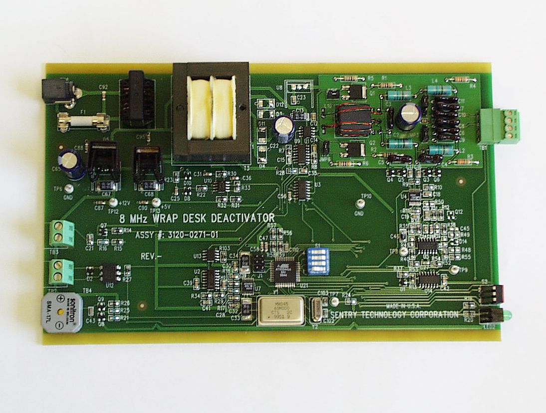
Wrap Desk Deactivator Theory of Operation Introduction The Wrap Desk Deactivator (WDD) is an accessory product normally used with the “P” and “ T” family of RF anti-theft (EAS) systems. These systems are generally installed in retail stores to protect merchandise from theft. The main elements of the system are the “P” or “T” series detection system installed near the store exit and the tags, which are attached to the items to be protected. Tags brought within a certain distance from the detection system cause an audible alarm to be generated. At the point of sale, the store clerk removes the tags from the merchandise as the items are paid for, allowing the customer to take the merchandise past the system without causing an alarm. The “WDD” described in the following, is a small tag detection system, which is placed near the checkout to help the clerk identify items, which may have a tag that is not readily visible. General Principle of Operation The WDD operates on the same principle as a radar system. A transmit signal at 2MHz that is generated within is radiated into the detection zone. The tag is a passive device containing a spiral antenna and a tuning capacitor, which is resonant at 2MHz. The tag absorbs energy from the field produced by the WDD and re-radiates the field at the tag’s resonant frequency. This re-radiated field is detected by an antenna and processed to produce an alarm. Circuit Description Overall Architecture The system is comprised of four basic sections: the transmitter electronics, the receiver electronics, the antenna pad and the power supply. The transmitter and receiver electronics are contained in a metal enclosure and the external pad is connected to it. The power is supplied from an external wall plug in transformer. DC supply voltages of +12V and +5V are then regulated and provided to the active circuitry. Transmitter Electronics The transmitter derives its basic timing and frequency control from U21, which is an 8- bit processor that operates on an 8MHz crystal. The main transmit carrier generating device is U7, a single chip Direct Digital Synthesis (DDS) IC that operates on a 40MHz clock module and is controlled by the processor. The DDS transmit carrier frequency is passed to the transmitter amplifier, a low pass filter and then to the antenna. A zero crossing detector starts a sequence of events that occurs at the same frequency as the AC line voltage. The sequence starts with a 7uS transmitter burst at a fixed frequency followed by a 43uS delay. This sequence occurs eight times, each time at a fixed frequency of 2MHz. The worst case duty cycle for the transmitter is 100*(7E-06 * 8 * 60 (line frequency)) = 0.336% Receiver Electronics During the time between each transmitter burst, the re-radiated field from the tag is passed to the receiver IC U4 which is a 100dB demodulating logarithmic amplifier. The detected output is amplified by U7, passed to U4 where it is sampled and fed to the comparator input on U21. If the signal from the tag has the same Q as that expected from a tag, the alarm is genera ted.
Operational Description
Wrap Desk Deactivator Theory of Operation Introduction The Wrap Desk Deactivator (WDD) is an accessory product normally used with the “P” and “ T” family of RF anti-theft (EAS) systems. These systems are generally installed in retail stores to protect merchandise from theft. The main elements of the system are the “P” or “T” series detection system installed near the store exit and the tags, which are attached to the items to be protected. Tags brought within a certain distance from the detection system cause an audible alarm to be generated. At the point of sale, the tags are removed from the merchandise or deactivated by the store clerk as the items are paid for, allowing the customer to take the merchandise past the system without causing an alarm. The “WDD” described in the following, is a small tag detection system, which is placed near the checkout to help the clerk identify items, which may have a tag that is not readily visible. General Principle of Operation The WDD operates on the same principle as a radar system. A transmit signal within the 7.5 to 8.9MHz band generated within is radiated into the detection or deactivation zone. The tag, which is a passive device containing a spiral antenna and a tuning capacitor, is a resonant circuit tuned within the 7.6 to 8.8 MHz band. The tag absorbs energy from the field produced by the WDD and re-radiates the field at the tag’s resonant frequency. This re-radiated field is detected by an antenna and processed to produce an alarm. Circuit Description Overall Architecture The system is comprised of four basic sections: the transmitter electronics, the receiver electronics, the antenna pad and the power supply. The transmitter and receiver electronics are contained in a metal enclosure and the external pad is connected to it. The power is supplied from an external wall plug in transformer. DC supply voltages of +12V and +5V are then regulated and provided to the active circuitry. Transmitter Electronics The transmitter derives its basic timing and frequency control from U21, which is an 8- bit processor that operates on an 8MHz crystal. The main transmit carrier generating device is U7, a single chip Direct Digital Synthesis (DDS) IC that operates on a 40MHz clock module and is controlled by the processor. The DDS transmit carrier frequency is passed to the transmitter amplifier, a low pass filter and then to the antenna. A zero crossing detector starts a sequence of events that occurs at the same frequency as the AC line voltage. The sequence starts with a 7uS transmitter burst at a fixed frequency followed by a 43uS delay. This sequence occurs eight times, each time at a fixed frequency of 7.5, 7.7, 7.9, 8.1, 8.3, 8.5, 8.7, and 8.9MHz. The worst case duty cycle for the transmitter is 100*(7E-06 * 60 (line frequency)) = 0.042% Receiver Electronics During the time between each transmitter burst, the re-radiated field from the tag is passed to the receiver IC U4 which is a 100dB demodulating logarithmic amplifier IC. The detected output is amplified by U7, passed to U4 where it is sampled and fed to the comparator input on U21. If the signal from the tag has the same Q as that expected from a tag, the alarm is genera ted.
Schematics
2MHz WDD_4-20-01.sch-1 - Fri Apr 20 10:26:08 2001
Schematics
8MHz WDD_4-2-01.sch-1 - Fri Apr 20 10:29:29 2001
Test Report
Retlif Testing Laboratories R Retlif Test Report Number R-8953 APPLICANT Knogo North America 350 Wireless Boulevard Hauppauge, NY 11788 Manufacturer Knogo North America 350 Wireless Boulevard Hauppauge, NY 11788 TEST SPECIFICATION: FCC Rules and Regulations Part 15, Subpart C TEST SAMPLE DESCRIPTION BRANDNAME: Knogo MODEL: 2MHz Wrap DeskFCC ID: TYPE: Pulsed Transmitter FREQUENCY RANGE: 2 MHz (Operated in the 1.705 to 10 MHz Band) POWER REQUIREMENTS: 18VDC derived from 115VAC, 60 Hz AC Adapter TESTS PERFORMED - 15.207(a)Conducted Emissions - 15.223(a)Radiated Emissions, Fundamental - 15.223(B)Occupied Bandwidth - 15.223(b)Radiated Emissions, Spurious Case - 15335(b)Duty Cycle Determination Retlif Testing Laboratories R Retlif Test Report Number R-8953 REPORT OF MEASUREMENTS Applicant:Knogo North America Device:Pulsed Transmitter FCC ID: Power Requirements:18VDC derived from an AC Adapter Applicable Rule Section:Part 15, Subpart C, Section 15.223 TEST RESULTS 15.207(a):The radio frequency voltage that was conducted back on to the AC power line on any frequency/frequencies within the bandwidth of 450kHz to 30MHz did not exceed 250 microvolts. 15.223(a):Field strength of emissions from the intentional radiator operating in the 1.705 - 10 MHz frequency band did not exceed 15 uV/m at 30 meters (average) for the fundamental. The 6dB bandwidth of the emission was less than 10% of the center frequency. 15.223(b):Field strength of emissions outside of the band 1.705 - 10 MHz did not exceed the general radiated emissions limits of 15.209. GENERAL NOTES 1.All user accessible controls were adjusted to produce maximum emissions. 2.Measurements of conducted emissions were performed utilizing a 50 ohm/50μhenry Line Impedance Stabilization Network (LISN). 3.The unit operated at single frequency centered at 2 MHz. 4.The frequency range was scanned from 1.705 MHz to 1 GHz. All emissions not reported were more than 20dB below the specified limit. Retlif Testing Laboratories R Retlif Test Report Number R-8953 DETERMINATION OF DUTY CYCLE The unit’s RF output was directly coupled to the input of the spectrum analyzer. The analyzer was set for a frequency span of 0Hz. The sweep time was then adjusted in order to display one full pulse train. The transmitter on time was then summed and compared to the time for one full cycle in order to obtain the duty cycle. (See plots for additional information) Transmitter On Time=336 microseconds (maximum- worst case in 100 ms) Transmitter Cycle Time=16.67 milliseconds Transmitter Duty Cycle=0.336 % (- 49.4 dB) SPECTRUM ANALYZER DESENSITIZATION CONSIDERATIONS Due to the nature of the emissions being measured, care was taken to ensure that the resolution bandwidth of the spectrum analyzer was adequate to provide accurate measurements. The following formula was utilized: Setting pulse desensitization equal to zero and utilizing the minimum observed pulse width of 7.0μs yields a minimum required bandwidth of 104,657 Hz. FCC specified bandwidths of 10 kHz below 30 MHz and 100kHz and 1MHz were utilized below and above 1GHz, respectively. For measurements below 30 MHz a pulsewidth desensitization factor of -19.6 dB was applied, derived from the following formula: P[dB] = 20 log (pulse width x bandwidth x1.5) Where pulse width = 7.0 microseconds and bandwidth = 10 kHz P[dB] = - 19.6 dB Retlif Testing Laboratories R Retlif Test Report Number R-8953 EXHIBIT 4 Radiated Emissions Para. 15.223(a) Para. 15.223(b) (Please see separate e-file attachment named ReFund.pdf and ReSpur.pdf) Retlif Testing Laboratories R Retlif Test Report Number R-8953 EXHIBIT 4 Occupied Bandwidth Para. 15.223(b) (Please see separate e-file attachment named OccBw.pdf) Retlif Testing Laboratories R Retlif Test Report Number R-8953 EXHIBIT 4 Duty Cycle Para. 15.35(b) (Please see separate e-file attachment named Dutycycle.pdf) Retlif Testing Laboratories R Retlif Test Report Number R-8953 EXHIBIT 4 Conducted Emissions Para. 15.107(a) (Please see separate e-file attachment named CeData.pdf) Retlif Testing Laboratories R Retlif Test Report Number R-8953 EQUIPMENT LISTS FCC15.207(a) Conducted Emissions, 450kHz to 30MHz ENTypeManufacturerDescriptionModel No.Cal DateDue Date 078LISNSolar Electronics10 kHz - 30 MHz8028-50-TS24BNC04/27/200004/27/2001 141Spectrum AnalyzerHewlett Packard100 Hz - 40 GHz8566B02/20/200108/20/2001 141AGraphics PlotterHewlett PackardN/A7470A03/05/200103/05/2002 141BQuasi-Peak AdaptorHewlett Packard100 Hz - 1 GHz85650A02/20/200108/20/2001 202Transient LimiterHewlett Packard.009 MHz - 200 MHz11947A07/24/200007/24/2001 513LISNSolar Electronics10 kHz - 30 MHz8028-50-TS24BNC04/27/200004/27/2001 617Interference AnalyzerElectro-Metrics10 kHz - 1 GHzEMC-3002/27/200102/27/2002 FCC15.223 Radiated Emissions Fundamental Frequency, 1.705MHz to 10MHz ENTypeManufacturerDescriptionModel No.Cal DateDue Date 012Loop Antenna, ActiveEMCO9 kHz - 30 MHz650210/3/0010/3/01 067Open Area Test SiteRetlif3 MeterRNY9/20/009/20/03 133Broadband Pre-AmplifierElectro-Metrics10 kHz - 1 GHz, 26dBBPA-10006/13/006/13/01 141Spectrum AnalyzerHewlett Packard100 Hz - 40 GHz8566B2/20/018/20/01 141AGraphics PlotterHewlett PackardN/A7470A3/5/013/5/02 141BQuasi-Peak AdaptorHewlett Packard100 Hz - 1 GHz85650A2/20/018/20/01 206B6.0 dB AttenuatorTexscan0 - 1.0 GHzFP-50 - 6 dB6/13/006/13/01 617Interference AnalyzerElectro-Metrics10 kHz - 1 GHzEMC-302/27/012/27/02 FCC15.223 Radiated Emissions, 1.705MHz to 1.0GHz ENTypeManufacturerDescriptionModel No.Cal DateDue Date 012Loop Antenna, ActiveEMCO9 kHz - 30 MHz650210/3/0010/3/01 067Open Area Test SiteRetlif3 MeterRNY9/20/009/20/03 133Broadband Pre-AmplifierElectro-Metrics10 kHz - 1 GHz, 26dBBPA-10006/13/006/13/01 141Spectrum AnalyzerHewlett Packard100 Hz - 40 GHz8566B2/20/018/20/01 141AGraphics PlotterHewlett PackardN/A7470A3/5/013/5/02 141BQuasi-Peak AdaptorHewlett Packard100 Hz - 1 GHz85650A2/20/018/20/01 206B6.0 dB AttenuatorTexscan0 - 1.0 GHzFP-50 - 6 dB6/13/006/13/01 523BiconilogElectro-Mecha…
Text truncated - open the document above for the full version.
Test Report
TABULAR DATA SHEET CUSTOMER: MODEL No.: TEST SAMPLE: SERIAL No.: TEST SPECIFICATION: TEST METHOD: OPERATING MODE: TECHNICIAN:DATE: RETLIF TESTING LABORATORIES NOTES: DATA SHEETOF JOB No.: PARAGRAPH: Correction factor includes Pulse Desensitization factor. PDF=19.6dB Extrapolated using 20 log (1/d)², formula. Extrapolation factor=-40dB 2MHz Transmitter R-8953 The frequency range was scanned from 1.705 MHz to 10 MHz. All emissions not recorded were more Than 10 dB below the specified limit. Emissions from the EUT do not exceed the specified limits. *=Noise Floor Measurements ( Minimum system sensitivity) 42.2 130.3 32.5 42.3 72.5 82.3 30.4 30.4 42.1 51.9 180 180 V/1.0 H/1.0 150 150 2.0 2.0 μV/mμV/mdBμVdBμVdBdBμVDegrees(V/H)MetersMHz Converted ReadingExtrapolated Reading Meter Reading Correction Factor Peak Limit @ 30m Corrected Reading EUT Orientation Antenna Position Frequency Continuously transmitting a signal at 2MHz. 15.223 FCC part 15 subpart C Peter LanannaMarch 26, 2001 FCC15.223(a) Radiated Emissions, Fundamental Frequency, 1.705MHz to 10MHz R-8953NATS 2MHzWrapDeskN/A 21 TABULAR DATA SHEET CUSTOMER: MODEL No.: TEST SAMPLE: SERIAL No.: TEST SPECIFICATION: TEST METHOD: OPERATING MODE: TECHNICIAN:DATE: RETLIF TESTING LABORATORIES NOTES: DATA SHEETOF JOB No.: PARAGRAPH: Duty Cycle Correction=20log(336μsec/100msec)=0.336% Duty Cycle Correction=20log(3.36m)=-49.4 dB 2MHz Transmitter R-8953 The frequency range was scanned from 1.705 MHz to 10 MHz. All emissions not recorded were more Than 10 dB below the specified limit. Emissions from the EUT do not exceed the specified limits. *=Noise Floor Measurements ( Minimum system sensitivity) 0.14 0.44 -16.9 -7.1 -49.4 -49.4 32.5 42.3 180 180 V/1.0 H/1.0 15 15 2.0 2.0 μV/mμV/mdBμVdBdBμVDegrees(V/H)MetersMHz Converted ReadingMeter Reading Duty Cycle Factor Average Limit @ 30m Corrected Reading EUT Orientation Antenna Position Frequency Continuously transmitting a signal at 2MHz. 15.223 FCC part 15 subpart C Peter LanannaMarch 26, 2001 FCC15.223(a) Radiated Emissions, Fundamental Frequency, 1.705MHz to 10MHz R-8953NATS 2MHzWrapDeskN/A 22
Test Report
Retlif Testing Laboratories R Retlif Job Number R-8953 Data Sheet 1 of 1 Test Method: FCC Part 15 Subpart C, Spurious Case Radiated Emissions, Paragraph 15.209(a) Customer: NATS Job No. R-8953 Test Sample: 2MHz Transmitter Model No.: 2MHzWrapDesk Serial No. N/A Operating Mode: Continuously transmitting a 2MHz signal. Technician: Peter Lananna Date: March 26, 2001 Notes: Test Distance: 3 Meters Temp:13C Humidity:62% Detector: Quasi-Peak 30 MHz to 1 GHz, Peak below 30MHz and above 1 GHz Test Freq. Antenna Position EUT Orientation Meter Readings Correction Factor Corrected Reading Converted Reading LIMIT MHz (V/H) / Meters Degrees dBuV dB dBuV/m uV/m uV/m 1.705 V/1.0 180 17.0 10.7 27.7 24.3* 3000 | | | | | | | | | | | | | | | | | | 30.00 3000 30.00 100 | | 56.2 V/1.0 338 39.4 -11.1 28.3 26.0 | l | 88.00 100 88.00 150 l | 118.2 V/1.0 022 32 -11.1 20.9 11.1 | 126.2 V/1.0 022 30 -11.6 18.4 8.3 | 130.0 V/1.0 180 29 -11.7 17.3 7.3 | l | 216.00 150 216.00 200 l | 960.00 200 960.00 500 l | 1000.0 500 The EUT was scanned from 1.705 MHz to 1 GHz The emissions observed from the EUT do not exceed the specified limits. Emissions not recorded were more than 10dB under the specified limit *Denotes minimum system sensitivity.
Test Report
APPLICANT Knogo North America 350 Wireless Boulevard Hauppauge, NY 11788 Manufacturer North American Technical Services 30 Northport Road Sound Beach, NY 11789-1734 TEST SPECIFICATION: FCC Rules and Regulations Part 15, Subpart C TEST SAMPLE DESCRIPTION BRANDNAME: Knogo MODEL: 8MWDDFCC ID: TYPE: Swept RF Transmitter FREQUENCY RANGE: 7.9 - 8.9 MHz POWER REQUIREMENTS: 18VAC derived from 115VAC, 60 Hz AC Adapter TESTS PERFORMED - 15.207(a)Conducted Emissions - 15.223(a)Radiated Emissions, Fundamental - 15.223(a)Occupied Bandwidth - 15.223(b)Radiated Emissions, Spurious REPORT OF MEASUREMENTS Applicant:Knogo North America Device:Swept RF Transmitter FCC ID: Power Requirements:18VAC derived from 115VAC, 60Hz AC Adapter Applicable Rule Section:Part 15, Subpart C, Section 15.223 TEST RESULTS 15.207(a):The radio frequency voltage that was conducted back on to the AC power line on any frequency/frequencies within the bandwidth of 450kHz to 30MHz did not exceed 250 microvolts. 15.223(a):Field strength of emissions from the intentional radiator operating in the 1.705 - 10 MHz frequency band did not exceed 100 uV/m average for the fundamental. The 6dB bandwidth of the emission was greater than 10% of the center frequency. 15.223(b):Field strength of emissions outside of the band 1.705 - 10 MHz did not exceed the general radiated emissions limits of 15.209. GENERAL NOTES 1.All user accessible controls were adjusted to produce maximum emissions. 2.Measurements of conducted emissions were performed utilizing a 50 ohm/50μhenry Line Impedance Stabilization Network (LISN). 3.The unit sweeps between 7.9 - 8.9 MHz. 4.The frequency range was scanned from 1.705 MHz to 1 GHz. All emissions not reported were more than 20dB below the specified limit. MODIFICATIONS Customer added Fair Rite brand Ferrite to the EUT, Model Number 0431164281, between the transmitter and the antenna, closest to transmitter. DETERMINATION OF DUTY CYCLE The unit’s RF output was directly coupled to the input of the spectrum analyzer. The analyzer was set for a frequency span of 0Hz. The sweep time was then adjusted in order to display one full pulse train. The transmitter on time was then summed and compared to the time for one full cycle in order to obtain the duty cycle.( See plots for additional information) Transmitter On Time=56 microseconds (maximum- worst case in 100 ms) Transmitter Cycle Time=16.67 milliseconds Transmitter Duty Cycle=0.336 % SPECTRUM ANALYZER DESENSITIZATION CONSIDERATIONS Due to the nature of the emissions being measured, care was taken to ensure that the resolution bandwidth of the spectrum analyzer was adequate to provide accurate measurements. The following formula was utilized: Setting pulse desensitization equal to zero and utilizing the minimum observed pulse width of 7.0μs yields a minimum required bandwidth of 104,657 Hz. FCC specified bandwidths of 10 kHz below 30 MHz and 100kHz and 1MHz were utilized below and above 1GHz, respectively. For measurements below 30 MHz a pulsewidth desensitization factor of -19.6 dB was applied, derived from the following formula: P[dB] = 20 log (pulse width x bandwidth x1.5) Where pulse width = 7.0 microseconds and bandwidth = 10 kHz P[dB] = - 19.6 dB EXHIBIT 4 Radiated Emissions Para. 15.223(a) Para. 15.223(b) (Please see separate e-file attachment named ReFund.pdf and RESpur.pdf) EXHIBIT 4 Occupied Bandwidth Para. 15.223(b) (Please see separate e-file attachment named OccBw.pdf) EXHIBIT 4 Conducted Emissions Para. 15.107(a) (Please see separate e-file attachment named CeData.pdf) EQUIPMENT LISTS FCC 15.207(a) Conducted Emissions, 450kHz-30MHz ENTypeManufacturerDescriptionModel No.Cal DateDue Date 078LISNSolar Electronics10 kHz - 30 MHz8028-50-TS24BNC04/27/200004/27/2001 202Transient LimiterHewlett Packard.009 MHz - 200 MHz11947A07/24/200007/24/2001 231AGraphics PlotterHewlett PackardN/A7440A08/03/200008/03/2001 513LISNSolar Electronics10 kHz - 30 MHz8028-50-TS24BNC04/27/200004/27/2001 544EMC AnalyzerHewlett Packard9.0 kHz - 1.8 GHz8591EM08/25/199909/25/2000 FCC 15.223(a) Fundamental Frequency, 1.705-10MHz ENTypeManufacturerDescriptionModel No.Cal DateDue Date 012Loop Antenna, ActiveEMCO9 kHz - 30 MHz650210/04/199910/04/2000 067Open Area Test SiteRetlif3 MeterRNY10/15/199710/15/2000 141Spectrum AnalyzerHewlett Packard100 Hz - 40 GHz8566B08/03/200002/03/2001 141AGraphics PlotterHewlett PackardN/A7470A03/08/200003/08/2001 141BQuasi-Peak AdaptorHewlett Packard100 Hz - 1 GHz85650A08/02/200002/02/2001 FCC15.209(a) Spurious Radiated Emissions, 1.705-1000MHz ENTypeManufacturerDescriptionModel No.Cal DateDue Date 012Loop Antenna, ActiveEMCO9 kHz - 30 MHz650210/04/199910/04/2000 067Open Area Test SiteRetlif3 MeterRNY10/15/199710/15/2000 133Broadband Pre-AmplifierElectro-Metrics10 kHz - 1 GHz, 26dBBPA-100006/13/200006/13/2001 141AGraphics PlotterHewlett PackardN/A7470A03/08/200003/08/2001 206B6.0 dB AttenuatorTexscan0 - 1.0 GHzFP-50 - 6 dB06/13/200006/13/2001 523BiconilogElectro-Mechanics26 - 2000 MHz3142B06/08/200006/08/2001 544EMC AnalyzerHewlett Packard9.0 kHz - 1.8 GHz8591EM08/25/199909/25/2000 617Interference AnalyzerElectro-Metrics10 kHz - 1 GHzEMC-3001/17/200001/17/2001
Test Report
TABULAR DATA SHEET CUSTOMER: MODEL No.: TEST SAMPLE: SERIAL No.: TEST SPECIFICATION: TEST METHOD: OPERATING MODE: TECHNICIAN:DATE: RETLIF TESTING LABORATORIES NOTES: DATA SHEETOF JOB No.: PARAGRAPH: Duty cycle=0.336% Duty cycle correction=-49.5 Tag detection system. R-8560 19.5 23.4 25.8 27.4 -49.5 -49.5 75.3 76.9 180 180 V/0° V/0° 100 100 7.9 8.9 μV/MμV/MdbμVdBdBμVdegreespol/oreintMHZ Converted Reading Corrected Reading Duty Cycle Factor Average Limit Actual Reading EUT Orientation Antenna Polarization Fundamental Frequency Transmitting a CW signal continuously, at frequency shown below. 15.223(a)FCC Part 15, subpart C. Peter LanannaAugust 01, 2000 FCC 15.223(a) Fundamental Frequency Measurement, 1.705-10MHz R-8560NATS (…
Text truncated - open the document above for the full version.
Contact Information
Applicant
Paula Mauro(Documentation Control)
516 232-2100Fax: 516 232-2124
Technical Contact
Nats Corp.Richard C Lanzillotto
[email protected]1631 744 0059
30 Northport rd · Sound Beach, New York · United States
Non-Technical Contact
Nats Corp.Richard C Lanzillotto
[email protected]1631 744 0059
Test Firm
Retlif Testing LaboratoriesMichael Bozza
Technical Specifications
| # | Rule Parts | Frequency Range | Power Output |
|---|---|---|---|
| 1 | 15C | 1.8 MHz - 8.9 MHz | - |
Other Applications from Knogo North America Inc
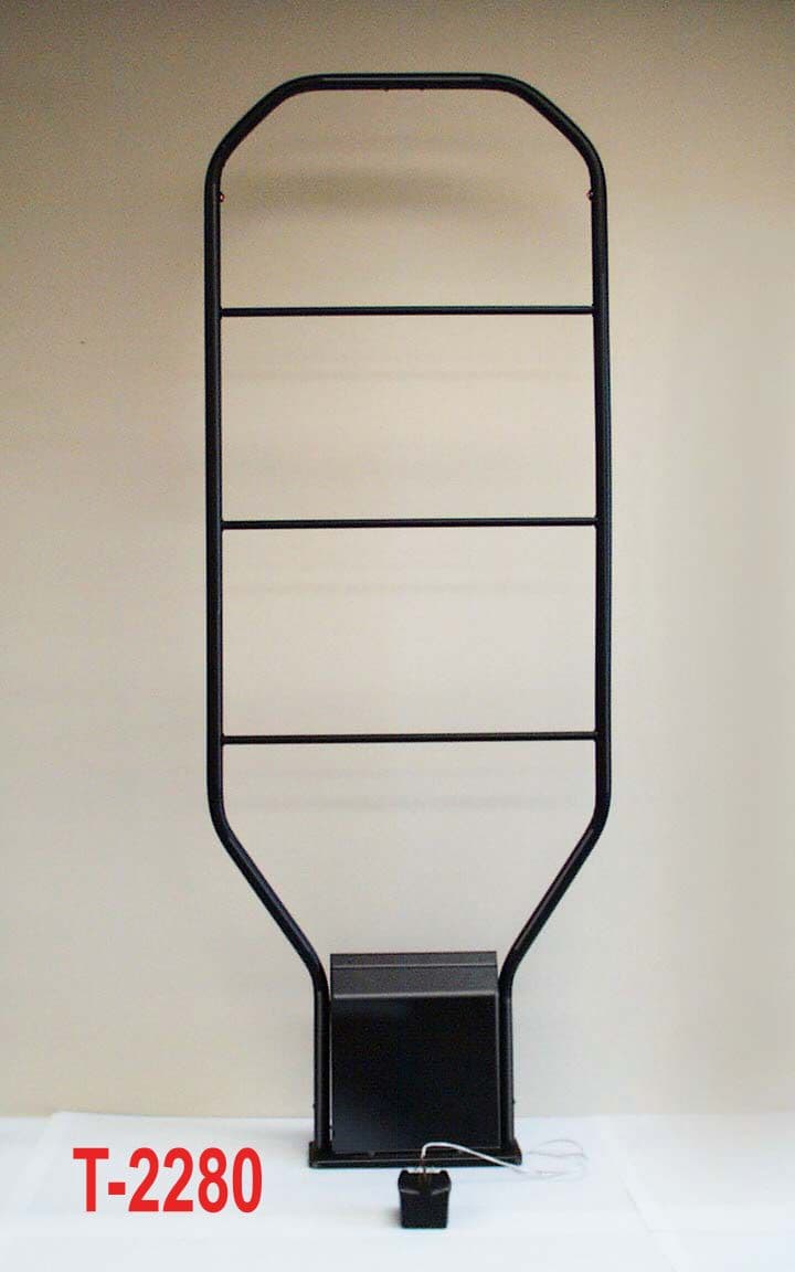
J3QT-2000
Dec 13, 2000FAP - Part 15 Anti-Pilferage Device
Equipment Class
FAP - Part 15 Anti-Pilferage Device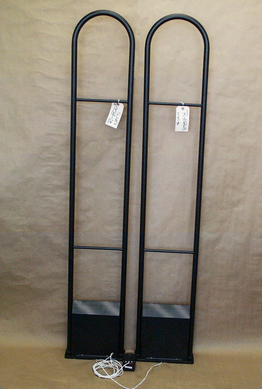
J3QP-2000
May 15, 2000FAP - Part 15 Anti-Pilferage Device
Equipment Class
FAP - Part 15 Anti-Pilferage DeviceJ3Q-2SRF-VD
Jan 23, 1997RF Card Reader
Equipment Class
FDS - Part 15 Field Disturbance SensorJ3Q3701
May 23, 1995Anti-Pilferage Device
Equipment Class
FDS - Part 15 Field Disturbance SensorJ3Q7201-915
Jul 22, 1992Range Finding System Transmitter
Equipment Class
DXX - Part 15 Low Power Communication Device Transmitter