JCK-GN-BR402WWireless Broadband Router
GIGA-BYTE TECHNOLOGY CO., LTD.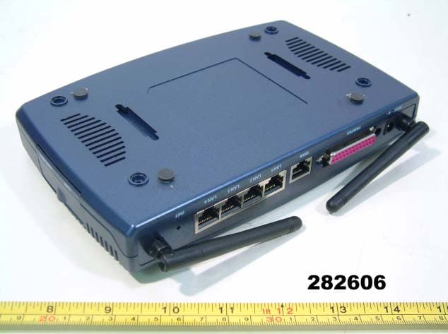
Click to zoom
Application Details
- Equipment Class
- DSS - Part 15 Spread Spectrum Transmitter
- Date of Grant
- Nov 19, 2002
- Application Purpose
- Original Equipment
- Date of Application
- Nov 19, 2002
- Equipment Note
- Wireless Broadband Router
- Frequency Range
- 2412.00000000 - 2462.00000000
- Country
- Taiwan
Documents & Files
Document Text
Text extracted from the exhibit documents filed with the FCC. Open a document above to read the original.
Users Manual
GN-BR402W FCC ID : JCK-GN-BR402W Wireless Broadband Router User’s Guide http://www.gigabyte.com.tw Rev. 1.0 First Edition Contents 1. PRODUCT INTRODUCTION.......................................................................................................1 1-1 About this Product.................................................................................................................................................1 1-2 Accessories................................................................................................................................................................1 1-3 Specifications............................................................................................................................................................1 1-4 LED Status..................................................................................................................................................................1 2. SYSTEM CONNECTION & INSTALLATION............................................................................2 2-1 ADSL/Cable Modem Requirements ..........................................................................................................2 2-2 PC Hardware Requirement at the PC End..........................................................................................2 2-3 Connection for Ethernet User........................................................................................................................3 2-4 Connection for USB Port User ...................................................................................................................3 2-5 Connection for PCMCIA Wireless Adapter User.............................................................................3 3. CONFIGURATION.........................................................................................................................4 3-1 Preparation.................................................................................................................................................................4 3-2 Setup at Your PC End .........................................................................................................................................4 3-2-1 The Settings Under Windows2000.........................................................................4 3-2-2 Setup Under the Windows 95/98/Me...................................................................12 3-2-3 Set Up Under Windows XP...................................................................................18 3-3 Setup for Broadband Router........................................................................................................................24 3-4 Wireless Basic Setting......................................................................................................................................38 3-5 Logout...........................................................................................................................................................................41 4. STATUS.........................................................................................................................................42 5. CHANGE PASSWORD..............................................................................................................44 6. CHANGE MAC ADDRESS........................................................................................................45 7. FIRMWARE UPGRADE.............................................................................................................46 8. INSTRUCTION OF USING SPECIAL APPLICATION..........................................................47 8-1 Instruction of Using DMZ....................................................................................................................................48 8-2 Instruction of Using Netmeeting..........................................................................................................................49 9. INSTRUCTION OF USING THE VIRTUAL SERVER...........................................................50 10. VLAN...........................................................................................................................................51 11. STATIC ROUTING TABLE.......................................................................................................52 12. TROUBLESHOOTING.............................................................................................................53 13. APPENDIX.................................................................................................................................54 (A) GN-BR402W Functional Diagram.................................................................................................................54 (B) USB Driver Installation ..........................................................................................................................................55 (C) Instruction of Printer Server..............................................................................................................................59 1 1. Product Introduction 1-1 About this Product Thank you for using Gigabyte GN-BR402W Wireless Broadband Router. This product comes with high-performance transmission rate and compatible wireless connectivity for either your home or business and will allow you to access the data whenever you want. You will be able to enjoy the freedom that wireless networking delivers. Additionally, GN-BR402W enables you to easily setup all procedures in no time before using this product 1-2 Accessories - Gigabyte GN-BR402W Broadband Router x 1 - Adapter (5V, 2A) x 1 - User’s Guide x 1 - CD (including User’s Guide and Software) x 1 -RJ45 Network Cable (Cross-Over) x 2 1-3 Specifications GN-BR402W Quantity Description LAN 4 10/100 Mbps, RJ-45 Insert Hole USB 1 USB (B type) Insert Hole WAN 1 10/100 Mbps, RJ-45…
Text truncated - open the document above for the full version.
Users Manual
32 Step 11. If you select the “Dynamic IP Address” in the WAN TYPE SELECT, the following screen will appear. First, select “Automatic” or “Manual” DNS. Please key in the Host Name and Manual DNS IP address if you select “Manual” DNS. Press “Finish” to go to next step. Step 12. After “Reboot” is pressed, it proceeds with the next step. 33 Step 13. Please wait a moment. Step 14. The IE browser will be automatically connected to the main menu, and the setup is completed by then. Please use your IE connect to Internet. If you can connect to the Internet , the setting is completed. If you use the Wireless Lan Card connection , please continue to section 3-4 Wireless Basic Setting. 34 Step 15. If you select “Static IP Address” in the WAN TYPE SELECT, please key in the data provided by the wideband company in the following fields as shown below: Note: a. If your wideband company gives you more than one IP address, then select one of them to fill in the column in the above figure, and refer to Appendix A for the use of other IP addresses. b. Static IP Setup Normal Users please use "NAT enable" then connect to Internet in general. Step 15. After “Reboot” is pressed, it proceeds with the next step. 35 Step 16. Please wait for a moment. Step 17. The IE browser will be automatically connected to the main menu, and the setup at the PC end is completed by then. Please use your IE connect to Internet. If you can connect to the Internet , the setting is completed . If you use the Wireless Lan Card connection , please continue to section 3-4 Wireless Basic Setting. 36 Step 18. If you select “PPP(Modem)” in the WAN TYPE SELECT, please key in the data provided by the ISP company in the following blanks , then click “finish” , shown as below: Step 19. After “Reboot” is pressed, it proceeds with the next step. 37 Step 20. Please wait for a moment. Step 21. The IE browser will be automatically connected to the main menu, and the setup at the PC end is completed by then. Please use your IE connect to Internet. If you can connect to the Internet, it means you have finished the setting. If you use the Wireless Lan Card connection, please continue to 3-4 Wireless Basic Setting. 38 3-4 Wireless Basic Setting Step 1. Please key in the data. Region Because of the different region has different open channel regulations, please choose your local area, system will change to your local area utilize channel list automatically. Channel Please choose the Channel where you at, different area has different channel range, the default value is channel 6. SSID The default value is “gigabyte”, if the setup value is the default value, like “router”, Only can accept the computer connection, which use the Wireless card ESSID (or SSID) set up, is “router”. Rate There are four chooses for the Maximum transition rates, 11Mbps/5.5Mbps/2Mbps/1Mbps. WEP Setup Five chooses as following: 1. Not use. 2. Using 64-bit WEP encryption, and using pass phase change to the key. For the wireless card portion, please setup the first set password value. 3. Using 64-bit WEP encryption, enter to the key manually, and be able to choose what group of key as well. 4. Using 128-bit WEP encryption, and using pass phase change to the key. For the wireless card portion, please fill up the password on the first set password area. 5. Using 128-bit WEP encryption, enter to the key manually. 39 Step2. “MAC Access Control” shown as the diagram. You can set up either “allow” or “deny” the user can connect to the Internet by setting the MAC address. Default Rules : Disable/Allow/Deny Disable : Disable MAC Address control. Allow : The user can connect to the Internet. Deny : The user cannot connect to the Internet. The format of MAC address is XX:XX:XX:XX:XX:XX.(exp. “01:23:45:67:89:AB”) Note Condition 1: "allow" It allows all users can connect to the Internet, except the users who set up under “deny” condition. Condition 2: "deny" It denies all users can connect to the Internet, except the users who set up under “allow” condition. Condition 3: All of the regulations from 1~12 won’t work if the status of default rule is “Disable”. All users can connect to the Internet. (The wireless card should enter correct SSID and WEP password value.) For instance: Case 1. Default Rule is “Allow”. Rule1: the MAC address is ”11:22:33:44:55:66” and the status is “deny”. Rule2: the MAC address is “77:88:99:AA:BB:CC” and the status is “deny”. c It allows all users can connect to the Internet, except the users whose MAC Address are “11:22:33:44:55:66” or “77:88:99:AA:BB:CC”. Case 2. Default Rule is “Deny”. Rule1: the MAC address is ”11:22:33:44:55:66” and the status is “allow”. Rule2: the MAC address is “77:88:99:AA:BB:CC” and the status is “allow”. c It denies all users can connect to the Internet, except the users whose MAC Address are “11:22:33:44:55:66” or “77:88:99:AA:BB:CC”. 40 Step3. Please wait for a moment. Step4. After the Wireless Basic setting is completed, check the status of the WAN connection. If the status is “connect” then you can use IE to the Internet, else please click the “connect” bottom to reconnect. 41 3-5 Logout After you finish GN-BR402W setup, please choose “ Logout”. Note : After 5 minutes idle time, the system will be automatically logout. 42 4. Status -“ Status” screen shows the current basic network setting status. Status 1. If you select “PPPoE” in the WAN TYPE SELECT, press “Status”, and the screen shows as follows: Note: your network service provider automatically obtains each of the above IP address at the WAN end. Status 2. If you select “Dynamic IP Address” in the WAN TYPE SELECT, press “Status” screen as follows: Note: your network service provider automatically obtains Each IP address of the above WAN end. 43 Status 3. If you select “Static IP Address” in the WAN TYPE SELECT, press “Status”, and the screen shows as follows: Status 3. If you select “PPP (Modem)” in the WAN TYPE SELECT, press “Status”, and the screen shows as follows: 44 5. Change P…
Text truncated - open the document above for the full version.
External Photos
FC C ID : JC K - GN - B R 402W FRONT SIDE OF EUT N u mber 1 REA R SIDE OF EUT N u mber 2 FC C ID : JC K - GN - B R 402W
ID Label/Location Info
FCC ID Label Drawing FCC ID : JCK-GN-BR402W
ID Label/Location Info
FCC ID : JCK-GN-BR402W FCC ID LOCATION
Internal Photos
FC C ID : JC K - GN - B R 402W N u m b e r 1 Close-up look of connector FC C ID : JC K - GN - B R 402W N u m b e r 2 M echanical C onst r uct i on FC C ID : JC K - GN - B R 402W N u m b e r 3 M echanical C onst r uct i on FC C ID : JC K - GN - B R 402W N u m b e r 4 Front side of Main Board FC C ID : JC K - GN - B R 402W N u m b e r 5 R ear side of M a in B o ard FC C ID : JC K - GN - B R 402W N u m b e r 6 Front side of Wireless LA N Module Card FC C ID : JC K - GN - B R 402W N u m b e r 7 Rear side of Wireless LA N Module Card FC C ID : JC K - GN - B R 402W N u m b e r 8 Mechanical Construction of Wireless LA N Module Card FC C ID : JC K - GN - B R 402W N u m b e r 9 Mechanical Construction of Wireless LA N Module Card FC C ID : JC K - GN - B R 402W N u m b e r 1 0 Front Side of Wireless LA N Module Card FC C ID : JC K - GN - B R 402W N u m b e r 1 1 Rear Side of Wireless LA N Module Card FC C ID : JC K - GN - B R 402W N u m b e r 1 2 Front Side of A d apter FC C ID : JC K - GN - B R 402W N u m b e r 1 3 R ear Side of A d apt e r FC C ID : JC K - GN - B R 402W N u m b e r 1 4 Mechanical Construction of A d apter FC C ID : JC K - GN - B R 402W N u m b e r 1 5 Mechanical Construction of A d apter FC C ID : JC K - GN - B R 402W N u m b e r 1 6 Mechanical Construction of A d apter FC C ID : JC K - GN - B R 402W N u m b e r 1 7 TP Cable FC C ID : JC K - GN - B R 402W N u m b e r 1 8 US B Ca ble
Operational Description
Operation Description FCC ID : JCK-GN-BR402W The transmitter of the EUT is use 1/4 dipole antenna with MMCX connector inside of EUT . The transmitter of EUT is powered by power adaptor and managed by computer via LAN port. The EUT have CPU (Arm7 32bit. RISC controller), WAN (1 Ethernet 10/100 Mbps WAN port) LAN (4 Ethernet 10/100 Mbps LAN port with Auto-negotiation function) Printer (1 Printer port). Under normal use condition, the user has to keep at least 20cm separation distance from radiator to body of the user. The EUT is a fixed equipment. The EUT is use IEEE 802.11b DSSS (Direct Sequence Spread Spectrum) technical. IEEE 802.11b data is encoded using DSSS (direct-sequence spread-spectrum) technology. DSSS works by taking a data stream of zeros and ones and modulating it with a second pattern, the chipping sequence. In 802.11, that sequence is known as the Barker code, which is an 11-bit sequence (10110111000) that has certain mathematical properties making it ideal for modulating radio waves. The basic data stream is exclusive OR'd with the Barker code to generate a series of data objects called chips. Each bit is "encoded" by the 11-bit Barker code, and each group of 11 chips encodes one bit of data. The wireless radio generates a 2.4-GHz carrier wave (2.4 to 2.483 GHz) and modulates that wave using a variety of techniques. For 1-Mbps transmission, BPSK (Binary Phase Shift Keying) is used (one phase shift for each bit). To accomplish 2-Mbps transmission, QPSK (Quadrature Phase Shift Keying) is used. QPSK uses four rotations (0, 90, 180 and 270 degrees) to encode 2 bits of information in the same space as BPSK encodes 1. CCK (Complementary Code Keying) to achieve 11 Mbps, it used a series of codes called Complementary Sequences. Because there are 64 unique code words that can be used to encode the signal, up to 6 bits can be represented by any one particular code word (instead of the 1 bit represented by a Barker symbol). The CCK coding is applied for increasing the data rate, the bit rates are 1,2,5.5.11 Mbps, the symbol rates are 1,1,1.375,1.375Mbps, the chip rates are always 11Mbps.
Schematics
5 5 4 4 3 3 2 2 1 1 DD CC BB AA (ICE Connector) ADM5106 0.1 BR402W 18Wednesday, August 14, 2002 Title SizeDocument NumberRev Date:Sheet of EESK EEDI EECS D10 D9 D8 D4 D5 D6 D7 DQM2 DQM3 A3 A2 A1 A0 A4 A5 A6 A7 D29 D28 D20 D21 D22 D23 D27 D25 D24 DQM0 DQM1 WE# CS# A11 A9 A10 A8 D11 TCK WAIT# TEST RD0- TD0+ RD1+ RD2- TD2+ TD3- TD3+ RD3+ D2 A19 EEDO DP A13 D14 D0 EEDO UCTS# A14 D1 DM D3 D26 TD1- UDSR# UVSS RD0+ UDCD# D15 D12 D17 F_OE# D13 RAS# LAN1 LAN3 F_WE# D31 RD1- A18 TD2- F_CS0# A17 D18 EEDI D16 RD2+ RD3- A16 A12 LAN2 TD1+ LAN4 TD0- D30 D19 CAS# A15 EECS EESK VDDAL UVDD RESET# TCK TDI TDI TMS TDO TDO TMS UVSS UVDD RESET# RESET# UDI1 UDO1 RESET#_X ICE_RESET# LAN18 LAN28 LAN38 LAN48 A132,4,5 A142,5 A152,5 A162,5 A172,5 A182,5 A192,5 D164 D174 D184 D194 D304 D314 F_WE#5,6,8 F_OE#5,6,8 F_CS0#5 DP4 DM4 UCTS#6 UDSR#6 UDCD#6 D04,5,6,8 D14,5,6,8 D24,5,6,8 D34,5,6,8 D124,5,8 D134,5,8 D144,5,8 D154,5,8 D114,5,8 D94,5,8 D64,5,6,8 D104,5,8 D44,5,6,8 D84,5,8 D54,5,6,8 DQM24 A12,4,5,6,8 D74,5,6,8 A32,4,5,6,8 DQM34 A22,4,5,6,8 A42,4,5,6,8 A04,5,6,8 A62,4,5,6,8 A52,4,5,6,8 A72,4,5,6,8 A102,4,5,6 A82,4,5,6,8 D284 D224 D274 D294 D214 D264 D204 D234 CLKOUT4 D254 RAS#4 DQM04 D244 DQM14 WE#4 CAS#4 A92,4,5,6,8 A112,5 CS#4 A122,4,5 CS#_P8 WAIT#8 INT_P8 TEST2 RD0+3 RD0-3 TD0+ 3 TD0-3 TD1- 3 RD1- 3 TD1+3 RD1+3 RD3+ 3 RD2+3 TD2+ 3 RD3- 3 RD2-3 TD3- 3 TD2-3 TD3+3 CS#_W6,8 INT_W6 GPIO78 GPIO84,7 GPIO58 UDI16 UDO16 RESET#_X7 RD4+3 RD4-3 TD4+3 TD4-3 WAN_LINK_ACT-8 RESET#5 VCC3 VCC25VCC3 VCC3VCC25 VCC3 VCC25 VCC3A VCC25A VCC3VCC3A VCC25AVCC25 VCC3 VCC3 VCC25A VCC3 VCC3 VCC25 SL1 0/8/S 12 SL2 0/8/S 12 SC70 0.1U/6/S RN118P4R-1K 1 3 5 7 2 4 6 8 C40 10U/12 R3 4.7K/6 C9 4.7U/12/X C149 0.1U/6 C160 10P/6/X C21 0.1U/6 C159 0.1U/6 C37 0.1U/6 C30 0.1U/6 L31 0/8 12 C28 0.1U/6 C11 0.1U/6 C31 0.1U/6 U2 NM93C46 1 2 3 45 6 7 8 CS SK DI DOGND N/C N/C VDD C22 0.1U/6 C23 4.7U/12 C1 22P/6 C13 0.1U/6 SC10100P/6/S C2 22P/6 L6 0/8 12 SR18 16K/6/1/S R1 1M/6 C29 0.1U/6 C12 0.1U/6 Y1 25MHZ/D 12 R1133/6 R6 10K/6 SR17 33/6/S SC91 470P/6/S R189 1.5K/6 C8 22P/6/X SC88 470P/6/S C17 0.1U/6 C36 0.1U/6L7 0/8 12 C16 0.1U/6 JP1 H_2X7/X 12 34 56 78 910 1112 1314 SL5 FB80/8/S 12 VCC GND U23 1G08 51 2 4 3 SC93 470P/6/S C34 0.1U/6 C25 4.7U/12 C35 0.1U/6 C27 0.1U/6 L20 0/8 12 Y2 48MHZ/D 12 SL4 FB80/8/S 12 SC92 470P/6/S C3 0.01U/6 C39 0.1U/6 C192 4.7U/12 C33 0.1U/6 U1 ADM5106 1 2 3 4 5 6 7 8 9 10 11 12 13 14 15 16 17 18 20 25 26 27 28 32 34 35 36 37 38 39 40 41 42 43 44 45 46 47 48 49 50 51 52 5358596066676869707172737475767778798081828384858687888990919293949596979899100101102104 105 106 107 108 109 110 111 112 113 114 115 117 118 119 120 121 122 123 124 125 126 127 128 129 130 131 132 133 134 135 136 137 138 139 140 141 142 143 144 145 146 147 148 149 150 151 152 153 154 155 156 157158159160161162163164165166167168169170171172173174175176177178179180181182183184185186187188189190191192193194195196197198199200201202203204205206207208 116 103 19 21 22 23 24 31 30 29 33 545556576162636465 VDDAL VSSA X1 X2 REF_RES NC UVSS DP DM UVDD VDDo UX1 UX2 EESK EECS EEDI EEDO GPIO[3] VSSi RESET# VDDi CRS0 COL0 TXD0[3]/NWAY# TXE0/RV_MII TXC0 VSSi RXC0 RXDV0 RXD0[0] RXD0[1] RXD0[2] RXD0[3] VDDo D[16] D[17] VDDi D[18] D[19] VSSo D[31] D[30] VSSi D[29]VDDoD[23]VDDiDQM[1]WE#VSSoCAS#RAS#VSSiCLK_OUTVDDiCS#A[12]/COL_ABTA[11]/LED[2]A[9]/LED[0]VDDoA[8]A[10]/LED[1]VSSiA[7]A[6]A[5]A[4]A[0]VSSoA[1]A[2]A[3]DQM[3]DQM[2]D[7]VDDiD[6]VDDoD[5]VSSiD[4]D[8]D[9]D[10]VSSo VDDo D[3] D[2] D[1] D[0] D[12] D[13] VDDi D[14] VSSo D[15] A[14]/BP1 A[15]/XFC A[16] VSSi A[17] A[18] A[19] VDDo F_WE# F_OE# F_CS1# F_CS0# VDDi MDC MDIO LED4[2] VSSo LED4[1] LED4[0] LED3[2] LED3[1] VSSi LED3[0] LED2[2] LED2[1] LED2[0] LED1[2] VDDi LED1[1] LED1[0] LED0[2] LED0[1] LED0[0] UDCD# VDDo UDSR# UCTS# UDI0 UDO0 VSSi UDI1 UDO1 VSSo TRST# TDI TDO VDDi TMS TCK GPIO[0] VDDo GPIO[1]GPIO[2] TEST VSST TXN4 TXP4 VSSA VDDAL RXN4 RXP4 VDDAH RXP3 RXN3 VDDAL VSSA TXP3 TXN3 VSSTVSST TXN2 TXP2 VSSA VDDAL RXN2 RXP2 VDDAH RXP1 RXN1 VDDAL VSSA TXP1 TXN1 VSSTVSST TXN0 TXP0 VSSA VDDAL RXN0 RXP0 VDDAH A[13]/BP0 D[11] GPIO[4] GPIO[5] GPIO[6] GPIO[7] GPIO[8] TXD0[2]/FULL# TXD0[1]/100M# TXD0[0]/FFC# VSSo D[28]D[20]D[21]D[22]D[27]D[26]D[25]D[24]DQM[0] L11 2.2U/8 1 2 C18 0.1U/6 SC89 470P/6/S C26 4.7U/12 L5 0/8 12 R422.1K/1 SC80 0.1U/6/S C19 0.1U/6 SC7 0.1U/6/S C15 0.1U/6 L4 0/8 12 C32 0.1U/6 C38 0.1U/6 C14 0.1U/6/X C4 22P/6/X 5 5 4 4 3 3 2 2 1 1 DD CC BB AA (PLL SETTING 100MHZ)(ARM/USB OBSERVED MODE) (5107 MII1#/GPIO)(Boot in 16bit) All jam back-pressure(SW SETTING) Enable 802.3x flow control (BP1) (TEST MODE)(Little Endian) 00-->8 bit,01-->16 bit,10-->32 bit (BP0) (COL_ABT)will not abort packet when meet 16 consecutive collisions (LED SETTING) (USB CXVR BYPASS)(SIMULATION MODE) CONFIGURATION 0.1 BR401W_ADM 28Wednesday, August 14, 2002 Title SizeDocument NumberRev Date:Sheetof A6 A8 A16A19A15TESTA18A17 A14 A5A4A3 A7 A13A12A11 A9A10 A2A1 A61,4,5,6,8 A81,4,5,6,8 A151,5A161,5A191,5TEST1A181,5A171,5 A141,5 A51,4,5,6,8A41,4,5,6,8A31,4,5,6,8 A71,4,5,6,8 A131,4,5A121,4,5A111,5 A101,4,5,6A91,4,5,6,8 A21,4,5,6,8A11,4,5,6,8 VCC3 VCC3VCC3VCC3VCC3VCC3 VCC3 VCC3VCC3VCC3 R17 10K/6 R40 10K/6 R16 10K/6/X R14 10K/6/X R34 10K/6 R33 10K/6 R31 10K/6 R48 10K/6/X R18 10K/6 R41 10K/6/X R28 10K/6 R38 10K/6 R15 10K/6 R52 10K/6 R25 10K/6 R24 10K/6 R45 10K/6 R12 10K/6/X R47 10K/6/X R50 10K/6 R29 10K/6/X R39 10K/6 R27 10K/6/X R51 10K/6 R26 10K/6 R35 10K/6 R46 10K/6 R32 10K/6 R49 10K/6/X 5 5 4 4 3 3 2 2 1 1 DD CC BB AA TX:RX=1:1 2KV2KV 2KV2KV 2KV RJ45 0.1 BR401W_ADM 38Wednesday, August 14, 2002 Title SizeDocument NumberRev Date:Sheetof CMT3 TX3+ TX1- TX1+ RX1+ CMT2 RX0+ RX3+ CMT1 RX3- RX1- TX2- TX3- RX0- CMT0 RX2+ TX2+ TX0+ TX0- RX2- BI22 TD0+ CMT2 RD2- TCT1 TCT3 TCT0 RX2- TX1+ BI02 RX3- RX3+ TX2+ RX1- RX0+ RX2+ TX3- TX2- RX1+ BI11 TX1- TX0- RX0- BI12 TX0+ TX3+ BI01 BI22 BI12 TD1- TD1+ RD2X RD3X TD2+ TD3- TD0- RD1X TD2- TD3+ BI11 CMT0 BI01 TCT2 RD0X RD0+ RD0- CMT1 CMT1X BI02 CMT0X CHASSIS GND CMT3 BI31 BI31 BI21 CHASSIS GND BI32 CHASSIS GND BI32 BI21 RD1+ RD1- RD3- RD3…
Text truncated - open the document above for the full version.
Test Report
FCC TEST REPORT Report No. : F282606 FCC TEST REPORT for 47 CFR, Part 15, Subpart C Equipment : Wireless Broadband Router Model No. : GN-BR402W FCC ID : JCK-GN-BR402W Filing Type : Certification Applicant : GIGA-BYTE TECHNOLOGY CO., LTD. No.6, Bau Chiang Road, Hsin-Tien, Taipei Hsien, Taiwan, R.O.C. The test result refers exclusively to the test presented test model / sample. Without written approval of SPORTON International Inc., the test report shall not be reproduced except in full. Certificate or Test Report must not be used by the applicant to claim the product in this test report endorsement by NVLAP or any agency of U.S. government. SPORTON International Inc. 6F, No.106, Sec. 1, Hsin Tai Wu Rd., Hsi Chih, Taipei Hsien, Taiwan, R.O.C. SPORTON International Inc. TEL : 886-2-2696-2468 FAX : 886-2-2696-2255 FCC TEST REPORT Report No. : F282606 Table of Contents History of this test report..................................................................................................................ii CERTIFICATE OF COMPLIANCE........................................................................................................................1 1. General Description of Equipment under Test.............................................................................................2 1.1. Applicant....................................................................................................................................................................................2 1.2. Manufacturer..............................................................................................................................................................................2 1.3. Basic Description of Equipment under Test................................................................................................................................2 2. Test Configuration of Equipment under Test...............................................................................................4 2.1. Test Manner...............................................................................................................................................................................4 2.2. Description of Test System.........................................................................................................................................................4 2.3. Connection Diagram of Test System..........................................................................................................................................7 3. Operation of Equipment under Test..............................................................................................................8 4. General Information of Test............................................................................................................................9 4.1. Standard for Methods of Measurement......................................................................................................................................9 4.2. Test in Compliance with.............................................................................................................................................................9 4.3. Frequency Range Investigated...................................................................................................................................................9 4.4. Test Distance.............................................................................................................................................................................9 5. Report of Measurements and Examinations..............................................................................................10 5.1. List of Measurements and Examinations..................................................................................................................................10 5.2. 6dB Bandwidth.........................................................................................................................................................................11 5.3. Peak Output Power..................................................................................................................................................................15 5.4. Power Spectral Density............................................................................................................................................................16 5.5. Test of Conducted Emission.....................................................................................................................................................20 5.6. Test of Radiated Emission........................................................................................................................................................24 5.7. Band Edges Measurement.......................................................................................................................................................33 5.8. Antenna Requirements.............................................................................................................................................................36 5.9. RF Exposure............................................................................................................................................................................37 6. EMI Suppression Component List...............................................................................................................39 7. Antenna Factor & Cable Loss......................................................................................................................40 8. List of Measuring Equipments Used...........................................................................................................42 9. Uncertainty of Test Site..........................................................................................................…
Text truncated - open the document above for the full version.
Test Setup Photos
FCC TEST REPORT Report No. : F282606 1.1. Photographs of Conducted Powerline Test Configuration z The photographs show the configuration that generates the maximum emission. FRONT VIEW REAR VIEW SPORTON International Inc. FCC ID : JCK-GN-BR402W TEL : 886-2-2696-2468 Page No. : 1 of 3 FAX : 886-2-2696-2255 Issued Date : Nov. 06, 2002 FCC TEST REPORT Report No. : F282606 SIDE VIEW SPORTON International Inc. FCC ID : JCK-GN-BR402W TEL : 886-2-2696-2468 Page No. : 2 of 3 FAX : 886-2-2696-2255 Issued Date : Nov. 06, 2002 FCC TEST REPORT Report No. : F282606 SPORTON International Inc. FCC ID : JCK-GN-BR402W TEL : 886-2-2696-2468 Page No. : 3 of 3 FAX : 886-2-2696-2255 Issued Date : Nov. 06, 2002 1.2. Photographs of Radiated Emission Test Configuration z The photographs show the configuration that generates the maximum emission. Handset FRONT VIEW REAR VIEW
Contact Information
Applicant
Alain Sam-Lai
Test Firm
SPORTON International IncKathy Lin
Technical Specifications
| # | Rule Parts | Frequency Range | Power Output |
|---|---|---|---|
| 1 | 15C | 2.41 GHz - 2.46 GHz | 6.00 mW |
Other Applications from GIGA-BYTE TECHNOLOGY CO., LTD.

JCKGM-AORUSM6
Jun 26, 2023Mouse
Equipment Class
DTS - Digital Transmission System
JCKS3
Jun 26, 2023Mouse Dongle
Equipment Class
DTS - Digital Transmission System
JCK28713AIREM60
Jul 30, 2015Sapphire Blue Optical Mouse
Equipment Class
DXX - Part 15 Low Power Communication Device Transmitter
JCK287137580RX
Jul 30, 2015Wireless Receiver
Equipment Class
DXX - Part 15 Low Power Communication Device Transmitter
JCK-MSN09C01
Feb 10, 2015NFC Controller Module with Integrated Antenna
Equipment Class
DXX - Part 15 Low Power Communication Device Transmitter