JCK-GN-WI02GMMini PCI Wireless Adapter
GIGA-BYTE TECHNOLOGY CO., LTD.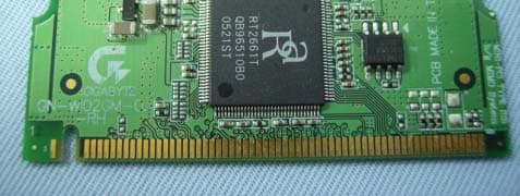
Click to zoom
Application Details
- Equipment Class
- DTS - Digital Transmission System
- Date of Grant
- Dec 20, 2005
- Application Purpose
- Original Equipment
- Date of Application
- Dec 20, 2005
- Equipment Note
- Mini PCI Wireless Adapter
- Frequency Range
- 2412.00000000 - 2462.00000000
- Country
- Taiwan
Documents & Files
Document Text
Text extracted from the exhibit documents filed with the FCC. Open a document above to read the original.
Users Manual
GN-WI02GM Mini PCI Wireless Adapter User’s Manual http://www.gigabyte.com.tw Rev. 1.0 First Edition Federal Communication Commission Interference Statement This equipment has been tested and found to comply with the limits for a Class B digital device, pursuant to Part 15 of the FCC Rules. These limits are designed to provide reasonable protection against harmful interference in a residential installation. This equipment generates, uses and can radiate radio frequency energy and, if not installed and used in accordance with the instructions, may cause harmful interference to radio communications. However, there is no guarantee that interference will not occur in a particular installation. If this equipment does cause harmful interference to radio or television reception, which can be determined by turning the equipment off and on, the user is encouraged to try to correct the interference by one of the following measures: -Reorient or relocate the receiving antenna. -Increase the separation between the equipment and receiver. -Connect the equipment into an outlet on a circuit different from that to which the receiver is connected. -Consult the dealer or an experienced radio/TV technician for help. This device complies with Part 15 of the FCC Rules. Operation is subject to the following two conditions: (1) This device may not cause harmful interference, and (2) this device must accept any interference received, including interference that may cause undesired operation. FCC Caution: Any changes or modifications not expressly approved by the party responsible for compliance could void the user's authority to operate this equipment. IMPORTANT NOTE: FCC Radiation Exposure Statement: This equipment complies with FCC radiation exposure limits set forth for an uncontrolled environment. This equipment should be installed and operated with minimum distance 20cm between the radiator & your body. This transmitter must not be co-located or operating in conjunction with any other antenna or transmitter. This device is intended only for OEM integrators under the following conditions: 1) The antenna must be installed such that 20 cm is maintained between the antenna and users, and 2) The transmitter module may not be co-located with any other transmitter or antenna. As long as 2 conditions above are met, further transmitter test will not be required. However, the OEM integrator is still responsible for testing their end-product for any additional compliance requirements required with this module installed (for example, digital device emissions, PC peripheral requirements, etc.). IMPORTANT NOTE: In the event that these conditions can not be met (for example certain laptop configurations or co-location with another transmitter), then the FCC authorization is no longer considered valid and the FCC ID can not be used on the final product. In these circumstances, the OEM integrator will be responsible for re-evaluating the end product (including the transmitter) and obtaining a separate FCC authorization. End Product Labeling This transmitter module is authorized only for use in device where the antenna may be installed such that 20 cm may be maintained between the antenna and users (for example :AP/Router/Motherboard). The final end product must be labeled in a visible area with the following: JCK-GN-WI02GM Manual Information That Must be Included The OEM integrator has to be aware not to provide information to the end user regarding how to install or remove this RF module in the users manual of the end product which integrate this module. The users manual for OEM integrators must include the following information in a prominent location “ IMPORTANT NOTE: To comply with FCC RF exposure compliance requirements, the antenna used for this transmitter must be installed to provide a separation distance of at least 20 cm from all persons and must not be co-located or operating in conjunction with any other antenna or transmitter. Contents END PRODUCT LABELING 3 MANUAL INFORMATION THAT MUST BE INCLUDED 3 CHAPTER 1. PRODUCT OVERVIEW 1 1-1. I NTRODUCTION.......................................................................................................... 1 1-2. FEATURES................................................................................................................ 1 1-3. PHYSICAL DIMENSIONS/PACKAGING............................................................................ 1 1-4. S YSTEM REQUIREMENTS............................................................................................ 2 CHAPTER 2. INSTALLING THE WLAN CARD 3 2-1. INSTALLING THE WIRELESS MINI-PCI ADAPTER........................................................... 3 2-2. D RIVER & UTILITY INSTALLATION - WINDOWS ® 98SE ................................................... 4 2-3. DRIVER & UTILITY INSTALLATION - WINDOWS ® ME....................................................... 6 2-4. DRIVER & UTILITY INSTALLATION - WINDOWS ® 2000 .................................................... 8 2-5. D RIVER & UTILITY INSTALLATION - WINDOWS ® XP ..................................................... 10 CHAPTER 3 USING THE GIGABYTE WLAN CONFIGURATION UTILITY 12 3-1. T HE PROFILE TAB.................................................................................................... 12 3-2. T HE LINK STATUS TAB............................................................................................. 19 3-3. THE SITE SURVEY TAB............................................................................................ 20 3-4. “S TATISTICS” SETTING............................................................................................. 21 3-5. THE ADVANCED TAB................................................................................................ 22 3-6. THE ABOUT TAB...................................................................................................... 23 CHAPTER 4 TROUBLESHOOTING 24 CANNOT ENABLE 802.1X, WPA OR WPA-…
Text truncated - open the document above for the full version.
Cover Letter(s)
Giga-Byte Technology Co., Ltd. NO.6, Bau Chiang Road, Hsin-Tien, Taipei Hsien, Taiwan, R.O.C. Attestation FCC ID JCK-GN-WI02GM Product Mini PCI Wireless Adapter Model GN-WI02GM Statements: We don’t provide with any controls or software to allow operation outside the USA frequency band for all future applications when we sell this product in USA. Sincerely, Signature: (Name / Date)
Cover Letter(s)
Transmitter Modular Approval Letter Date: December 01, 2005 Federal Communications Commission Re: Application Modular Approval Certification for FCC ID: JCK-GN-WI02GM Gentlemen: The following attestation addresses the eight requirements to support Modular approval as required by the FCC Public Notice DA 00-1407” Part 15 Unlicensed Modular Transmitter Approval” 1 The modular transmitter has its own RF shielding.(Refer to “Internal Photograph Exhibit”) 2 The modular transmitter has buffered modulation/data inputs. All inputs to the modules are buffered through the radio circuitry. (Refer to “Block Diagram and Schematics Exhibit”) 3 The modular transmitter has its own power supply regulator.(Refer to “Block Diagram and Schematics Exhibit ”and Bill of Materials Exhibit”) 4 The modular transmitter has an antenna that complies with section 15.203 of the FCC rules. It has a UFL type of connector at the transmitter end and is Swivel Access Point Antenna (depending on OEM configuration). Also the antenna will be internal in the OEM host equipment and inaccessible to the user.(Refer to “Operational Description Exhibit” and “Antenna Specification Exhibit”) 5 The modular transmitter was tested outside of a host desktop computer using a PCI extender card. The PCI extender card allows the transmitter to be placed outside of the chassis of the host desktop computer.(Refer to “Test Configuration”in Compliance Certificaiton Services Inc. test report and to “External Photograph Exhibit”) 6 The modular transmitter will be labeled with it own FCC ID. Also, the OEM host computer manufacturer will be informed to display a label referring to the enclosed module. The exterior habel will read as follows: “Contains Transmitter Module FCC ID: JCK-GN-WI02GM” or “Contains TX FCCID: JCK- GN-WI02GM” (Refer to “Label Information Exhibit”) 7 The modular transmitter is manufactured so that the user cannot influence the operation of the transmitter that will operate outside of the scope of the regulations.(Refer to“User’s Guide Exhibit) 8 The modular transmitter meets the MPE calculations of 47 CFR 1.1307(b)(1) (Refer to “RF Exposure Exhibit”.)
External Photos
Compliance Certification Services Inc.Report No.51115403-RP1 External Photo ( Model : GN-WI02GM)
ID Label/Location Info
Company : GIGA-BYTE TECHNOLOGY CO., LTD. Model : GN-WI02GM Product : Mini PCI Wireless Adapter Mini PCI Wireless Adapter Model No: GN-WI02GM FCC ID: JCK-GN-WI02GM This device complies with part 15 of the FCC Rules. Operation is subject to the following two conditions: [1] this device may not cause harmful interference and [2] this device must accept any interference received, including interference that may cause undesired operation. S/N Made in Taiwan Label Here
Internal Photos
Compliance Certification Services Inc.Report No.51115403-RP1
RF Exposure Info
Compliance Certification Services Inc. Report No: 51115403-RP1 FCC ID: JCK-GN-WI02GM Date of Issue: November 28, 2005 Page 1 TEST RESULTS No non-compliance noted Te s t D a t a Test mode: IEEE 802.11b Channel Frequency (MHz) Reading Power(dBm) Factor (dB) Output Power(dBm) Output Power(W) Limit(W) Result Low 2412 25.96 1 26.96 0.49659 PASS Mid 2437 26.14 1 27.14 0.51761 PASS High 2462 27.02 1 28.02 0.63387 1 PASS Test mode: IEEE 802.11g Channel Frequency (MHz) Reading Power(dBm) Factor (dB) Output Power(dBm) Output Power(W) Limit(W) Result Low 2412 24.36 1 25.36 0.34356 PASS Mid 2437 24.54 1 25.54 0.35810 PASS High 2462 25.38 1 26.38 0.43451 1 PASS Compliance Certification Services Inc. Report No: 51115403-RP1 FCC ID: JCK-GN-WI02GM Date of Issue: November 28, 2005 Page 2 RADIO FREQUENCY EXPOSURE LIMIT Systems operating under the provisions of this section shall be operated in a manner that ensures that the public is not exposed to radio frequency energy levels in excess of the Commission's guidelines. See §15.247(i) and §1.1307(b)(1) of this chapter. EUT Specification EUT Mini PCI Wireless Adapter Frequency band (Operating) WLAN: 2.412GHz ~ 2.462GHz WLAN: 5.18GHz ~ 5.32GHz / 5.50GHz ~ 5.70GHz WLAN: 5.745GHz ~ 5.825GHz Others Device category Portable (<20cm separation) Mobile (>20cm separation) Others Exposure classification Occupational/Controlled exposure (S = 5mW/cm2) General Population/Uncontrolled exposure (S=1mW/cm2) Antenna diversity Single antenna Multiple antennas Tx diversity Rx diversity Tx/Rx diversity Max. output power 28.02dBm (633.87mW) Antenna gain (Max) 4.5 dBi (Numeric gain: 2.8184) Evaluation applied MPE Evaluation SAR Evaluation Remark: 1. The maximum output power is 28.02(633.87mW) at 2462MHz (with 2.8184 numeric antenna gain.) 2. DTS device is not subject to routine RF evaluation; MPE estimate is used to justify the compliance. 3. For mobile or fixed location transmitters, no SAR consideration applied. The minimum separation generally be used is at least 20 cm, even if the calculations indicate that the MPE distance would be lesser. TEST RESULTS No non-compliance noted. Compliance Certification Services Inc. Report No: 51115403-RP1 FCC ID: JCK-GN-WI02GM Date of Issue: November 28, 2005 Page 3 Calculation Given d GP E ×× = 30 & 3770 2 E S = Where E = Field Strength in Volts / meter P = Power in Watts G=Numeric antenna gain d=Distance in meters S=Power Density in milliwatts / square centimeter Combining equations and re-arranging the terms to express the distance as a function of the remaining variables yields: S GP d × ×× = 3770 30 Changing to units of mW and cm, using: P (mW) = P (W) / 1000 and d (cm) =100 * d (m) Yields S GP S GP d × ×= × ×× ×= 282.0 3770 )1000/(30 100 Where d = distance in cm P = Power in mW G = Numeric antenna gain S = Power Density in mW / cm^2 Substituting the logarithmic form of power and gain using: P (mW) = 10 ^ (P (dBm) / 10) and G (numeric) = 10 ^ (G (dBi) / 10) Yields 20 10 282.0 20 )(GP d + ×= Equation 1 Where d = MPE safe distance in cm P = Power in dBm G = Antenna Gain in dBi S = Power Density Limit in mW / cm^2 Compliance Certification Services Inc. Report No: 51115403-RP1 FCC ID: JCK-GN-WI02GM Date of Issue: November 28, 2005 Page 4 Maximum Permissible Exposure (2.4 GHz Band) EUT output power = 633.8697mW Antenna Gain = 2.818383 (Numeric gain) S = 1.0 mW / cm^2 from 1.1310 Table 1 Substituting these parameters into the above Equation 1: Æ MPE Safe Distance =12.03538cm (For mobile or fixed location transmitters, the minimum separation distance is 20 cm, even if calculations indicate that the MPE distance would be less.)
Test Report
Compliance Certification Services Inc. Report No: 51115403-RP1 FCC ID: JCK-GN-WI02GM Date of Issue: November 28, 2005 Note: This report shall not be reproduced except in full, without the written approval of Compliance Certification Services Inc. This document may be altered or revised by Compliance Certification Services Inc. personnel only, and shall be noted in the revision section of the document. Page 1 FCC 47 CFR PART 15 SUBPART C TEST REPORT For Mini PCI Wireless Adapter Model Number: GN-WI02GM Trade Name: GIGA-BYTE Issued to GIGA-BYTE TECHNOLOGY CO., LTD. No.6, Bau Chiang Road, Hsin-Tien, Taipei Hsien, Taiwan, R.O.C. Issued by Compliance Certification Services Inc. Ta i n a n L a b . No. 8, Jiu Ceng Ling, Jiaokeng Village,Sinhua Township, Tainan Hsien 712, Taiwan R.O.C. TEL: 886-6-580-2201 FAX: 886-6-580-2202 Compliance Certification Services Inc. Report No: 51115403-RP1 FCC ID: JCK-GN-WI02GM Date of Issue: November 28, 2005 Page 2 TABLE OF CONTENTS 1. TEST RESULT CERTIFICATION....................................................................................................3 2. EUT DESCRIPTION ...........................................................................................................................4 3. TEST METHODOLOGY ....................................................................................................................5 3.1 EUT CONFIGURATION.......................................................................................................................5 3.2 EUT EXERCISE..................................................................................................................................5 3.3 GENERAL TEST PROCEDURES............................................................................................................5 3.4 FCC PART 15.205 RESTRICTED BANDS OF OPERATIONS .......................................................6 3.5 DESCRIPTION OF TEST MODES...........................................................................................................7 4. INSTRUMENT CALIBRATION........................................................................................................7 5. FACILITIES AND ACCREDITATIONS ..........................................................................................8 5.1 FACILITIES.........................................................................................................................................8 5.2 EQUIPMENT.......................................................................................................................................8 5.3 LABORATORY ACCREDITATIONS AND LISTING.................................................................................8 5.4 TABLE OF ACCREDITATIONS AND LISTINGS......................................................................................9 6. SETUP OF EQUIPMENT UNDER TEST .......................................................................................10 6.1 SETUP CONFIGURATION OF EUT......................................................................................................10 6.2 SUPPORT EQUIPMENT ...............................................................................................................10 7. FCC PART 15.247 REQUIREMENTS.............................................................................................11 7.1 6DB BANDWIDTH ........................................................................................................................11 7.2 PEAK POWER...................................................................................................................................15 7.3 BAND EDGES MEASUREMENT ................................................................................................20 7.4 PEAK POWER SPECTRAL DENSITY...................................................................................................30 7.5 RADIO FREQUENCY EXPOSURE........................................................................................................34 7.6 SPURIOUS EMISSIONS ...............................................................................................................37 7.7 POWER LINE CONDUCTED EMISSIONS.............................................................................................62 8. APPENDIX 1 PHOTOGRAPHS OF TEST SETUP .......................................................................65 Compliance Certification Services Inc. Report No: 51115403-RP1 FCC ID: JCK-GN-WI02GM Date of Issue: November 28, 2005 Page 3 1 TEST RESULT CERTIFICATION Applicant GIGA-BYTE TECHNOLOGY CO., LTD. Address No.6, Bau Chiang Road, Hsin-Tien, Taipei Hsien, Taiwan, R.O.C. Equipment Under Test Mini PCI Wireless Adapter Model Number GN-WI02GM Trade Name GIGA-BYTE Date of Test November 27 ~ November30, 2005 APPLICABLE STANDARDS STANDARD TEST RESULT FCC 47 CFR Part 15 Subpart C No non-compliance noted We hereby certify that: The above equipment was tested by Compliance Certification Services Inc. The test data, data evaluation, test procedures, and equipment configurations shown in this report were made in accordance with the procedures given in ANSI C63.4 and the energy emitted by the sample EUT tested as described in this report is in compliance with the requirements of FCC Rules Part 15.207, 15.209, 15.247. The test results of this report relate only to the tested sample EUT identified in this report. Approved by: Reviewed by: November 29,2005 November 29,2005 Alex Chiu Jeter Wu Manager Section Manager Compliance Certification Services Inc. Compliance Certification Services Inc. Compliance Certification Services Inc. Report No: 51115403-RP1 FCC ID: JCK-GN-WI02GM Date of Issue: November 28, 2005 Page 4 2 EUT DESCRIPTION Product Mini PCI Wireless Adapter Model Number GN-WI02GM Trade Name GIGA-BYTE Model Discrepancy N/A Power Supply Powered from Note Book Frequency Range 2412 ~ 2462 MHz Transmit Power IEEE802.11b mode: 28.02 dBm IEEE…
Text truncated - open the document above for the full version.
Test Setup Photos
Compliance Certification Services Inc. Report No: 51115403-RP1 FCC ID: JCK-GN-WI02GM Date of Issue: November 28, 2005 Page 65 8 APPENDIX 1 PHOTOGRAPHS OF TEST SETUP Radiated Emission Set up Photos Compliance Certification Services Inc. Report No: 51115403-RP1 FCC ID: JCK-GN-WI02GM Date of Issue: November 28, 2005 Page 66 Conducted Emission Set Up Photos Compliance Certification Services Inc. Report No: 51115403-RP1 FCC ID: JCK-GN-WI02GM Date of Issue: November 28, 2005 Page 67
Contact Information
Applicant
Alain Sam-Lai
Test Firm
Compliance Certification Service Inc.Paul Liau
Technical Specifications
| # | Rule Parts | Frequency Range | Power Output |
|---|---|---|---|
| 2 | 15C | 2.41 GHz - 2.46 GHz | 435.00 mW |
Other Applications from GIGA-BYTE TECHNOLOGY CO., LTD.

JCKGM-AORUSM6
Jun 26, 2023Mouse
Equipment Class
DTS - Digital Transmission System
JCKS3
Jun 26, 2023Mouse Dongle
Equipment Class
DTS - Digital Transmission System
JCK28713AIREM60
Jul 30, 2015Sapphire Blue Optical Mouse
Equipment Class
DXX - Part 15 Low Power Communication Device Transmitter
JCK287137580RX
Jul 30, 2015Wireless Receiver
Equipment Class
DXX - Part 15 Low Power Communication Device Transmitter
JCK-MSN09C01
Feb 10, 2015NFC Controller Module with Integrated Antenna
Equipment Class
DXX - Part 15 Low Power Communication Device Transmitter