JCK-GN-WIAG02IEEE 802.11b/g Wireless LAN Mini-PCI Card
GIGA-BYTE TECHNOLOGY CO., LTD.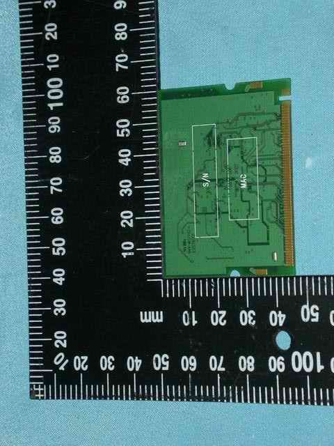
Click to zoom
Application Details
- Equipment Class
- DTS - Digital Transmission System
- Date of Grant
- Mar 15, 2005
- Application Purpose
- Original Equipment
- Date of Application
- Mar 15, 2005
- Equipment Note
- IEEE 802.11b/g Wireless LAN Mini-PCI Card
- Frequency Range
- 2412.00000000 - 2462.00000000
- Country
- Taiwan
Documents & Files
Document Text
Text extracted from the exhibit documents filed with the FCC. Open a document above to read the original.
Users Manual
GN-WIAG02 IEEE 802.11b/g Mini-PCI Wireless LAN Card User’s Manual http://www.gigabyte.com.tw Rev. 1.0 First Edition Federal Communication Commission Interference Statement This equipment has been tested and found to comply with the limits for a Class B digital device, pursuant to Part 15 of the FCC Rules. These limits are designed to provide reasonable protection against harmful interference in a residential installation. This equipment generates, uses and can radiate radio frequency energy and, if not installed and used in accordance with the instructions, may cause harmful interference to radio communications. However, there is no guarantee that interference will not occur in a particular installation. If this equipment does cause harmful interference to radio or television reception, which can be determined by turning the equipment off and on, the user is encouraged to try to correct the interference by one of the following measures: - Reorient or relocate the receiving antenna. - Increase the separation between the equipment and receiver. - Connect the equipment into an outlet on a circuit different from that to which the receiver is connected. - Consult the dealer or an experienced radio/TV technician for help. FCC Caution: To assure continued compliance,any changes or modifications not expressly approved by the party responsible for compliance could void the user's authority to operate this equipment. This device complies with Part 15 of the FCC Rules. Operation is subject to the following two conditions: (1) This device may not cause harmful interference, and (2) this device must accept any interference received, including interference that may cause undesired operation. IMPORTANT NOTE: FCC Radiation Exposure Statement: This equipment complies with FCC radiation exposure limits set forth for an uncontrolled environment. End users must follow the specific operating instructions for satisfying RF exposure compliance. This transmitter must not be co-located or operating in conjunction with any other antenna or transmitter. Contents CHAPTER 1 PRODUCT OVERVIEW 1 1-1. INTRODUCTION...........................................................................................................1 1-2. FEATURES.................................................................................................................1 1-3. PHYSICAL DIMENSIONS/PACKAGING.............................................................................1 1-4. S YSTEM REQUIREMENTS............................................................................................1 CHAPTER 2 INSTALLING THE WLAN CARD 2 2-1. INSTALLING THE DRIVER & UTILITY (WIN98SE/ME)......................................................2 2-2. I NSTALLING THE DRIVER & UTILITY (WIN2000/XP) .......................................................8 CHAPTER 3 USING THE UTILITY 12 3-1. LINK STATUS............................................................................................................12 3-2. SITE SURVEY...........................................................................................................16 3-3. CONFIGURATION......................................................................................................17 3-4. STATISTICS..............................................................................................................23 3-5. DRIVER INFO............................................................................................................24 CHAPTER 4 TROUBLESHOOTING 25 YOU ARE “802.1X”, “WPA” AND “WPA-PSK” CAN NOT BE SELECTED...........................25 I CANNOT CONNECT TO AN AP ...................................................................................25 I CAN CONNECT TO AN AP BUT I CANNOT CONNECT TO THE INTERNET...........................25 I ALWAYS HAVE POOR LINK QUALITY AND LOW SIGNAL..................................................26 CHAPTER 5 SPECIFICATION 27 1 Chapter 1 Product Overview 1-1. Introduction This 802.11b/g Wireless Local Area Network (WLAN) card is composed of the MAC, Baseband, and radio components, Mini-PCI interface, and two built-in antennas. It operates in 2.4GHz frequency bands, providing fast (up to 108Mbps) and secure (support AES, 802.1x & WEP and WAP) connections to 802.11b and 802.11g networks from a single card. 1-2. Features Conforms to 802.11b/802.11g specification. Transmits data rate up to the maximum speed of 108Mbps. Dynamically scales the data rate. Automatic power management to reduce battery consumption. Two antenna connectors for supporting antenna diversity. Seamless roaming between 802.11b and 802.11g networks. Supports AES (Advance Encryption System), enterprise-class 802.1x security and multiple levels of WEP encryption (64-bit /128-bit/152-bit), and WPA (Wi-Fi Protected Access).. Driver supports Windows 98SE/Me/2000/XP. 1-3. Physical Dimensions/Packaging Dimensions: 59mm* 44mm* 4mm 1-4. System Requirements 1-4-1. Supported Platform: IBM PC/AT compatible computer 1-4-2. Supported Operation System: Windows 98SE/Me/2000/XP 2 Chapter 2 Installing the WLAN Card 2-1. Installing The Driver & Utility (Win98SE/ME) Step 1: Click “Next”, and Insert our setup CD into your CDROM drive. Step 2: Click “Search for the best driver for your device” , and Click “Next”. Win 98 SE 3 Win ME Step 3: Click “Specify a location” , Click “Browse” , Click “CD-ROM Device:” , Select the directory “\Inf\Win98(Win Me)”, and Click “Next”. Win 98 SE 4 Win 98 SE Step 4: Click “Next”. 5 Step 5: Click “Finish”. Step 6: Click “No”. Step 7: Click “Install Wireless LAN Utility”. 6 Step 8: Click “Next” (Win 98 SE only). Step 9: Click “I accept this agreement” , and Click “Next” (Win 98 SE only). 7 Step 10: Click “Next” (Win 98 SE only). Step 11: Click “Finish” (Win 98 SE only). Step 12: Click “OK” (Win 98 SE only). 8 Step 13: Click “Finish” and Reboot you computer. 2-2. Installing The Driver & Utility (Win2000/XP) Step 1: Click “Cancel” Win 2K 9 Win XP S…
Text truncated - open the document above for the full version.
Attestation Statements
Giga-Byte Technology Co., Ltd. No. 6, Bau Chiang Road, Hsin-Tien, Taipei Hsien, Taiwan, ROC Attestation FCC ID :JCK-GN-WIAG02 Product :IEEE 802.11b/g Wireless LAN Mini-PCI Card Model :GN-WIAG02 Statements: We don’t provide with any controls or software to allow operation outside the USA frequency band for all future applications when we sell this product in USA. Sincerely, Signature: (Name / Date) Eric Hsu
Cover Letter(s)
Giga-Byte Technology Co., Ltd. No. 6, Bau Chiang Road, Hsin-Tien, Taipei Hsien, Taiwan, ROC Confidentiality Request FCC ID :JCK-GN-WIAG02 Product :IEEE 802.11b/g Wireless LAN Mini-PCI Card Model :GN-WIAG02 Pursuant to Sections 0.457 and 0.459 of the Commission’s Rules, the Applicant hereby requests confidential treatment of information accompanying this Application as outlined below. Schematics / Block Diagram/Operational Description The above materials contain trade secrets and proprietary information not customarily released to the public. The public disclosure of these matters might be harmful to the Applicant and provide unjustified benefits to its competitors. The Applicant understands that pursuant to Rule 0.457, disclosure of this Application And all accompanying documentation will not be made before the date of the Grant for this application. Sincerely, Signature: (Name / Date) Eric Hsu
Cover Letter(s)
Transmitter Modular Approval Letter Date: March 14, 2005 Federal Communications Commission Re: Application Modular Approval Certification for FCC ID: JCK-GN-WIAG02 Gentlemen: The following attestation addresses the eight requirements to support Modular approval as required by the FCC Public Notice DA 00-1407” Part 15 Unlicensed Modular Transmitter Approval” 1 The modular transmitter has its own RF shielding.(Refer to “Internal Photograph Exhibit”) 2 The modular transmitter has buffered modulation/data inputs. All inputs to the modules are buffered through the radio circuitry. (Refer to “Block Diagram and Schematics Exhibit”) 3 The modular transmitter has its own power supply regulator.(Refer to “Block Diagram and Schematics Exhibit ”and Bill of Materials Exhibit”) 4 The modular transmitter has an antenna that complies with section 15.203 of the FCC rules. It has a UFL type of connector at the transmitter end and is Dipole antenna (depending on OEM configuration). Also the antenna will be internal in the OEM host equipment and inaccessible to the user.(Refer to “Operational Description Exhibit” and “Antenna Specification Exhibit”) 5 The modular transmitter was tested outside of a host desktop computer using a PCI extender card. The PCI extender card allows the transmitter to be placed outside of the chassis of the host desktop computer.(Refer to “Test Configuration”in Compliance Certificaiton Services Inc. test report and to “External Photograph Exhibit”) 6 The modular transmitter will be labeled with it own FCC ID. Also, the OEM host computer manufacturer will be informed to display a label referring to the enclosed module. The exterior habel will read as follows: “Contains Transmitter Module FCC ID: JCK-GN-WIAG02” or “Contains TX FCCID: JCK- GN-WIAG02” (Refer to “Label Information Exhibit”) 7 The modular transmitter is manufactured so that the user cannot influence the operation of the transmitter that will operate outside of the scope of the regulations.(Refer to“User’s Guide Exhibit) 8 The modular transmitter meets the MPE calculations of 47 CFR 1.1307(b)(1) (Refer to “RF Exposure Exhibit”.)
External Photos
Compliance Certification Services Inc. Report No.:50223303 Page 1 of 11 External Photo Compliance Certification Services Inc. Report No.:50223303 Page 2 of 11 Compliance Certification Services Inc. Report No.:50223303 Page 3 of 11 Compliance Certification Services Inc. Report No.:50223303 Page 4 of 11 Antenna (1) gain : Main 4.5dBi, Aux 2dBi Compliance Certification Services Inc. Report No.:50223303 Page 5 of 11 Antenna (2) gain : Main 2dBi, Aux 2dBi
ID Label/Location Info
Company : GIGA-BYTE TECHNOLOGY CO., LTD. Model : GN-WIAG02 Product : IEEE 802.11b/g Wireless LAN Mini-PCI Card IEEE 802.11b/g Wireless LAN Mini-PCI Card Model No: GN-WIAG02 FCC ID:JCK-GN-WIAG02 This device complies with part 15 of the FCC Rules. Operation is subject to the following two conditions: [1] this device may not cause harmful interference and [2] this device must accept any interference received, including interference that may cause undesired operation. S/N: Made in Taiwan Label Here
Internal Photos
Compliance Certification Services Inc. Report No.:50223303 Page 6 of 11 Internal Photo Compliance Certification Services Inc. Report No.:50223303 Page 7 of 11 Compliance Certification Services Inc. Report No.:50223303 Page 8 of 11 Compliance Certification Services Inc. Report No.:50223303 Page 9 of 11 Compliance Certification Services Inc. Report No.:50223303 Page 10 of 11 Compliance Certification Services Inc. Report No.:50223303 Page 11 of 11
RF Exposure Info
!Compliance Certification Services Inc.!FCC ID : JCK-GN-WIAG02! Report No.Κ50223303RP2 Page1 of 2! ! RF EXPOSURE EVALUATION According to FCC 1.1310 : The criteria listed in the following table shall be used to evaluate the environment impact of human exposure to radio frequency (RF) radiation as specified in 1.1307(b) LIMITS FOR MAXIMUM PERMISSIBLE EXPOSURE (MPE) Frequency Range (MHz) Electric Field Strength (V/m) Magnetic Field Strength (A/m) Power Density (mW/cm 2 ) Average Time (A) Limits for Occupational / Control Exposures 300-1,500 -- -- F/300 6 1,500-100,000 -- -- 5 6 (B) Limits for General Population / Uncontrol Exposures 300-1,500 -- -- F/1500 6 1,500-100,000 -- -- 1 30 Friis Formula Friis transmission formula : P d = (P out *G)/(4*p i *r 2 ) Where P d = power density in mW/cm 2 P out = output power to antenna in mW G = gain of antenna in linear scale P i = 3.1416 r = distance between observation point and center of the radiator in cm P d is the limit of MPE, 1 mW/cm 2 . If we know the maximum gain of the antenna and the total power input to the antenna, through the calculation, we will know the distance “r” where the MPE limit is reached. EUT Operating Condition A software provided by client enabled the EUT to transmit and receive data at lowest, middle and highest channel individually. !Compliance Certification Services Inc.!FCC ID : JCK-GN-WIAG02! Report No.Κ50223303RP2 Page2 of 2! ! Test Result of RF Exposure Evaluation Test Item Κ RF Exposure Evaluation Data Test Mode Κ Normal Operation Antenna Gain Antenna GainΚThe maximum Gain measured in fully anechoic chamber is 4.5dBi linear scale. Output Power into Antenna & RF Exposure Evaluation Distance Channel Channel Frequency (MHz) Output Power to Antenna (dBm) Antenna Gain Power Density at 20cm (mW/cm2) LIMITS (mW/cm 2 ) CH 1 2412 26.03 4.5 0.224766 1 CH 6 2437 25.61 4.5 0.204047 1 CH 11 2462 26.08 4.5 0.227368 1 Note : 1. For 802.11b Mode (11Mbps) 2. The power density Pd (4th column) at a distance of 20cm calculated from the fries transmission formula is far below the limit of 1 mW/cm 2 . The EUT is classified as mobile product. So, RF exposure limit warning or SAR test are not required. 3. The EUT is classified as mobile module. RF exposure evaluation will be evaluated after the EUT is installed with the host. Channel Channel Frequency (MHz) Output Power to Antenna (dBm) Antenna Gain Power Density at 20cm (mW/cm2) LIMITS (mW/cm 2 ) CH 1 2412 23.55 4.5 0.126978 1 CH 6 2437 23.90 4.5 0.137635 1 CH 11 2462 23.64 4.5 0.129637 1 Note : 1. For 802.11g Mode (54Mbps). 2. The power density Pd (4th column) at a distance of 20cm calculated from the fries transmission formula is far below the limit of 1 mW/cm 2 . The EUT is classified as mobile product. So, RF exposure limit warning or SAR test are not required. 3. The EUT is classified as mobile module. RF exposure evaluation will be evaluated after the EUT is installed with the host. Channel Channel Frequency (MHz) Output Power to Antenna (dBm) Antenna Gain Power Density at 20cm (mW/cm2) LIMITS (mW/cm 2 ) 6 2437 22.75 4.5 0.105616 1 Note : 1. For 802.11g Turbo mode (108 Mbps) 2. The power density Pd (4th column) at a distance of 20cm calculated from the fries transmission formula is far below the limit of 1 mW/cm 2 . The EUT is classified as mobile product. So, RF exposure limit warning or SAR test are not required. 3. The EUT is classified as mobile module. RF exposure evaluation will be evaluated after the EUT is installed with the host. !
Test Report
Compliance Certification Services Inc. FCC ID : JCK-GN-WIAG02 Report No.:50223303RP2 Page 1 of 66 RF TEST REPORT Product Name : IEEE 802.11b/g Wireless LAN Mini-PCI Card Model Number : GN-WIAG02 Brand Name : GIGABYTE FCC ID : JCK-GN-WIAG02 Applicant : GIGA-BYTE TECHNOLOGY CO., LTD. Address : No. 6, Bau Chiang Road, Hsin-Tien, Taipei Hsien, Taiwan, R.O.C. Received Date : November 08, 2004 Tested Date : November 09, 2004 ~ March 10, 2005 Issued by Compliance Certification Services Inc. Hsinchu Lab. Rm. 258, Bldg. 17, NO.195, Sec.4 Chung HsingRd., ChuTung Chen, Hsinchu, Taiwan 310, R.O.C TEL: (03) 591-8012 FAX: (03) 582-5720 Notes : 1. This report will be invalid if duplicated or photocopied in part. 2. This report refers only to the specimen(s) submitted to testing, and be invalid as seperately used. 3. This report is invalid without examination stamp and signature of this institute. 4. The tested specimen(s) will be preserved for thirty days from the data issued. 5. The report must not be used to claim product certification, approval, or endorsement by NVLAP, NIST, or any agency of the federal government. Compliance Certification Services Inc. FCC ID : JCK-GN-WIAG02 Report No.:50223303RP2 Page 2 of 66 Test Report Certification Product Name : IEEE 802.11b/g Wireless LAN Mini-PCI Card Model Number : GN-WIAG02 Brand Name : GIGABYTE FCC ID : JCK-GN-WIAG02 Applicant : GIGA-BYTE TECHNOLOGY CO., LTD. Measurement Standard : FCC 47 C.F.R. Part 15, Subpart B and Subpart C (2004), ANSI C63.4 (2003) WE HEREBY CERTIFY THAT: The measurements shown in the attachment were made in accordance with the procedures indicated, and the energy emitted by the equipment was found to be within the limits applicable. We assume full responsibility for the accuracy and completeness of these measurements and vouch for the qualifications of all persons taking them. Compliance Certification Services Inc. FCC ID : JCK-GN-WIAG02 Report No.:50223303RP2 Page 3 of 66 TABLE OF CONTENTS TITLE PAGE NO. 1. GENERAL INFORMATION ................................................................................................... 5 1.1 General Statement ...............................................................................................................................5 1.2 General Description of EUT & Power ................................................................................................5 1.3 Tested Channel....................................................................................................................................6 1.4 Description of Peripherals...................................................................................................................7 1.5 EUT & Peripherals Setup Diagram.....................................................................................................7 1.6 EUT Operating Condition ...................................................................................................................8 1.7 Description of Test Site.......................................................................................................................9 1.8 Summary of Test Results ....................................................................................................................10 2. CONDUCTED POWERLINE TEST....................................................................................... 11 2.1 Test Equipments..................................................................................................................................11 2.2 Test Setup............................................................................................................................................11 2.3 Conducted Power Line Emission Limit ..............................................................................................12 2.4 Test Procedure.....................................................................................................................................12 2.5 Uncertainty of Conducted Emission ...................................................................................................12 2.6 Conducted RF Voltage Measurement .................................................................................................13-16 2.7 Photos of Conduction Test ..................................................................................................................17 3. RADIATED EMISSION TEST ................................................................................................ 18 3.1 Test Equipments..................................................................................................................................18 3.2 Test Setup............................................................................................................................................18 3.3 Radiation Limit ...................................................................................................................................19 3.4 Test Procedures ...................................................................................................................................20 3.5 Uncertainty of Radiated Emission ......................................................................................................20 3.6 Radiated RF Noise Measurement........................................................................................................21-41 3.7 Photos of Open Site.............................................................................................................................42-43 4. 6dB BANDWIDTH MEASUREMENT ................................................................................... 44 4.1 Test Equipments..................................................................................................................................44 4.2 Test Setup........................................................................................................…
Text truncated - open the document above for the full version.
Test Setup Photos
Compliance Certification Services Inc. FCC ID : JCK-GN-WIAG02 Report No.:50223303RP2 Page 17 of 66 2.7 Photos of Conduction Test Compliance Certification Services Inc. FCC ID : JCK-GN-WIAG02 Report No.:50223303RP2 Page 42 of 66 3.7 Photos of Open Site Compliance Certification Services Inc. FCC ID : JCK-GN-WIAG02 Report No.:50223303RP2 Page 43 of 66
Contact Information
Applicant
Alain Sam-Lai
Test Firm
Compliance Certification Services Inc.Paul Liau
Technical Specifications
| # | Rule Parts | Frequency Range | Power Output |
|---|---|---|---|
| 1 | 15C | 2.41 GHz - 2.46 GHz | 406.00 mW |
Other Applications from GIGA-BYTE TECHNOLOGY CO., LTD.

JCKGM-AORUSM6
Jun 26, 2023Mouse
Equipment Class
DTS - Digital Transmission System
JCKS3
Jun 26, 2023Mouse Dongle
Equipment Class
DTS - Digital Transmission System
JCK28713AIREM60
Jul 30, 2015Sapphire Blue Optical Mouse
Equipment Class
DXX - Part 15 Low Power Communication Device Transmitter
JCK287137580RX
Jul 30, 2015Wireless Receiver
Equipment Class
DXX - Part 15 Low Power Communication Device Transmitter
JCK-MSN09C01
Feb 10, 2015NFC Controller Module with Integrated Antenna
Equipment Class
DXX - Part 15 Low Power Communication Device Transmitter