JCK-GN-WIKGWireless mini-PCI Module
GIGA-BYTE TECHNOLOGY CO., LTD.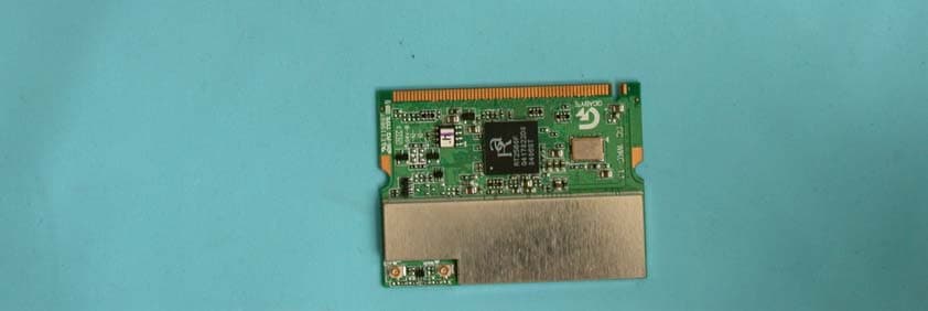
Click to zoom
Application Details
- Equipment Class
- DTS - Digital Transmission System
- Date of Grant
- Jun 15, 2004
- Application Purpose
- Original Equipment
- Date of Application
- Jun 15, 2004
- Equipment Note
- Wireless mini-PCI Module
- Frequency Range
- 2412.00000000 - 2462.00000000
- Country
- Taiwan
Documents & Files
Document Text
Text extracted from the exhibit documents filed with the FCC. Open a document above to read the original.
Users Manual
GN-WIKG IEEE 802.11b/g Wireless LAN Mini-PCI Card User’s Manual http://www.gigabyte.com.tw Rev. 1.0 First Edition Federal Communication Commission Interference Statement This equipment has been tested and found to comply with the limits for a Class B digital device, pursuant to Part 15 of the FCC Rules. These limits are designed to provide reasonable protection against harmful interference in a residential installation. This equipment generates, uses and can radiate radio frequency energy and, if not installed and used in accordance with the instructions, may cause harmful interference to radio communications. However, there is no guarantee that interference will not occur in a particular installation. If this equipment does cause harmful interference to radio or television reception, which can be determined by turning the equipment off and on, the user is encouraged to try to correct the interference by one of the following measures: -Reorient or relocate the receiving antenna. -Increase the separation between the equipment and receiver. -Connect the equipment into an outlet on a circuit different from that to which the receiver is connected. -Consult the dealer or an experienced radio/TV technician for help. This device complies with Part 15 of the FCC Rules. Operation is subject to the following two conditions: (1) This device may not cause harmful interference, and (2) this device must accept any interference received, including interference that may cause undesired operation. FCC Caution: Any changes or modifications not expressly approved by the party responsible for compliance could void the user's authority to operate this equipment. IMPORTANT NOTE: FCC Radiation Exposure Statement: This equipment complies with FCC radiation exposure limits set forth for an uncontrolled environment. This equipment should be installed and operated with minimum distance 20cm between the radiator & your body. This transmitter must not be co-located or operating in conjunction with any other antenna or transmitter. This device is intended only for OEM integrators under the following conditions: 1) The antenna must be installed such that 20 cm is maintained between the antenna and users, and 2) The transmitter module may not be co-located with any other transmitter or antenna. As long as 2 conditions above are met, further transmitter test will not be required. However, the OEM integrator is still responsible for testing their end-product for any additional compliance requirements required with this module installed (for example, digital device emissions, PC peripheral requirements, etc.). IMPORTANT NOTE: In the event that these conditions can not be met (for example certain laptop configurations or co-location with another transmitter), then the FCC authorization is no longer considered valid and the FCC ID can not be used on the final product. In these circumstances, the OEM integrator will be responsible for re-evaluating the end product (including the transmitter) and obtaining a separate FCC authorization. End Product Labeling This transmitter module is authorized only for use in device where the antenna may be installed such that 20 cm may be maintained between the antenna and users (for example :AP/Router/Motherboard). The final end product must be labeled in a visible area with the following: JCK-GN-WIKG Manual Information That Must be Included The OEM integrator has to be aware not to provide information to the end user regarding how to install or remove this RF module in the users manual of the end product which integrate this module. The users manual for OEM integrators must include the following information in a prominent location “ IMPORTANT NOTE: To comply with FCC RF exposure compliance requirements, the antenna used for this transmitter must be installed to provide a separation distance of at least 20 cm from all persons and must not be co-located or operating in conjunction with any other antenna or transmitter. Contents CHAPTER 1. PRODUCT OVERVIEW 1 1-1. INTRODUCTION...........................................................................................................1 1-2. FEATURES.................................................................................................................1 1-3. P HYSICAL DIMENSIONS/PACKAGING.............................................................................1 1-4. SYSTEM REQUIREMENTS............................................................................................2 CHAPTER 2. INSTALLING THE WLAN CARD 3 2-1. INSTALLING THE WIRELESS MINI-PCI ADAPTER............................................................3 2-2. D RIVER & UTILITY INSTALLATION - WINDOWS ® 98SE ....................................................4 2-3. DRIVER & UTILITY INSTALLATION - WINDOWS ® ME .......................................................8 2-4. D RIVER & UTILITY INSTALLATION - WINDOWS ® 2000...................................................12 2-5. D RIVER & UTILITY INSTALLATION - WINDOWS ® XP ......................................................17 CHAPTER 3 USING THE GIGABYTE WLAN CONFIGURATION UTILITY 21 3-1. T HE PROFILE TAB....................................................................................................21 3-2. T HE LINK STATUS TAB..............................................................................................28 3-3. THE SITE SURVEY TAB.............................................................................................29 3-4. “S TATISTICS” SETTING..............................................................................................30 3-5. THE ADVANCED TAB.................................................................................................31 3-6. THE ABOUT TAB.......................................................................................................32 CHAPTER 4 TROUBLESHOOTING 33 CANNOT ENABLE 802.1X, WPA OR WPA-PSK.......................................................…
Text truncated - open the document above for the full version.
Users Manual
7 Step 9: The Windows file explorer opens. Double-click on the file “AegisI2.exe”. Step 10: When the AEGIS Protocol Installation window appears click the Install button to begin installing program files. Step 11: When the message AEGIS Protocol Installed Successfully appears in the dialog box, click the Cancel button. Windows ® 98 may or may not automatically reboot your PC. 8 2-3. Driver & Utility Installation - Windows ® ME Step 1: When the Add New Hardware Wizard screen appears, click Cancel to exit. Step 2: Insert the GN-WIKG Installation CD into the CD-ROM drive. The GIGABTYE GN-WIKG Wireless Mini-PCI Adapter setup screen appears. Step 3: Drag your mouse over Install Wireless LAN Utility and click on it to start the utility installation program. 9 Step 4: When the Welcome screen appears, click Next. Step 5: The Check Setup Information screen displays the Operating System of your computer. If it is correct, click Next to continue. 10 Step 6: An information box screen appears. Click OK to go to the next screen. Step 7: After the software utility installation is complete, click Finish. You are now ready to install 802.1x authentication software. Step 8: Drag your mouse over Browse the CD and click on it. 11 Step 9: The Windows file explorer opens. Double-click on the file “Aegisl2.exe” Step 10: When the AEGIS Protocol Installation window appears click the Install button to begin installing program files. Step 11: When the message AEGIS Protocol Installed Successfully appears in the dialog box, click the Cancel button. Windows ® ME may or may not automatically reboot your PC. 12 2-4. Driver & Utility Installation - Windows ® 2000 Step 1: When the Found New Hardware Wizard screen appears, click Cancel to exit. Step 2: Insert the GN-WIKG Installation CD into the CD-ROM drive. The GIGABTYE GN-WIKG Wireless Mini-PCI Adapter setup screen appears. Step 3: Drag your mouse over Install Wireless LAN Utility and click on it to start the utility installation program. 13 Step 4: When the Welcome screen appears, click Next. Step 5: The Check Setup Information screen displays the Operating System of your computer. If it is correct, click Next to continue. 14 Step 6: After the software utility installation is complete, click Finish. You are now ready to install 802.1x authentication software. 15 Step 7: If the screen below appears, this does not mean there is a problem. Click Yes to continue. Step 8: Drag your mouse over Browse the CD and click on it. 16 Step 9: The Windows file explorer opens. Double-click on the file “AegisI2.exe”. Step 10: When the AEGIS Protocol Installation window appears click the Install button to begin installing program files. Step 11: When the message Installed Successfully appears in the dialog box, click the Close button. Windows ® 2000 may or may not automatically reboot your PC.
Users Manual
17 2-5. Driver & Utility Installation - Windows ® XP Step 1: When the Found New Hardware Wizard screen appears, click Cancel to exit. Step 2: Insert the GN-WIKG Installation CD into the CD-ROM drive. The GIGABTYE GN-WIKG Wireless Mini-PCI Adapter setup screen appears. Step 3: Drag your mouse over Install Wireless LAN Utility and click on it to start the utility installation program. 18 Step 4: When the Welcome screen appears, click Next. Step 5: The Check Setup Information screen displays the Operating System of your computer. If it is correct, click Next to continue. 19 Step 6: After the software utility installation is complete, click Finish. You are now ready to install 802.1x authentication software. Step 7: Drag your mouse over Browse the CD and click on it. 20 Step 8: The Windows file explorer opens. Double-click on the file “AegisI5.exe”. Step 9: When the AEGIS Protocol Installation window appears click the Install button to begin installing program files. Step 10: When the message Installed Successfully appears in the dialog box, click the Close button. Windows ® XP may or may not automatically reboot your PC. 21 Chapter 3 Using the GIGABYTE WLAN Configuration Utility The Gigabyte WLAN Utility is a powerful application that helps you to configure the GN-WIKG Wireless Mini-PCI Adapter as well as monitor the network status link. It automatically appears as an icon in the system tray at the bottom right corner of screen whenever the card is operating (see Figure 3-1). The icon displays signal strength (one green box = weak signal, 4 green boxes = strong signal) and double-clicking on it launches the utility. Figure 3-1 Gigabyte Configuration & Monitor Utility Icon You may also open the Gigabyte WLAN Utility from the Windows Start menu, selecting Programs and then Gigabyte WLAN Utility. Note: Modifications to WLAN configuration settings can be done when GN-WIKG is in use or through the network configuration tool provided by Windows ® when it is inactive. 3-1. The Profile Tab Click on the Profile tab in the Gigabyte WLAN Configuration Utility to view the values for each defined profile. Click the Add button to create a new profile (see section below for further details), the Delete button to delete a selected profile, the Edit button to modify a selected profile and click the Activate button to have a selected profile become active. Figure 3-2 Profile Tab 22 Profile Name - Name associated with specific wireless parameters and settings. The icon indicates the currently active profile. SSID – Displays the Service Set Identity (wireless network name) associated with active profile. Channel – Displays which channel the profile is operating on. Authentication – Displays authentication type associated with profile. Encryption – Four encryption types currently used in the profile include “None”, “WEP”, “AES” and “TKIP”. Network Type – Displays the wireless mode (Infrastructure or Ad-Hoc) associated with the profile. 3-1-1. Add Profile – Configuration Tab Figure 3-3 Add Profile – Configuration Tab 23 Profile Name – Type in a unique profile name, set the corresponding parameters and click the Apply button to add profile. SSID – Select a defined Service Set Identity detected by the system from the drop-down list or input a new SSID (32-character maximum). Power Saving Mode – Select the PSM option to enable power saving feature (when no data will be transmitted) or the CAM option to have device always on. Network Type – Displays the current wireless mode (Infrastructure or Ad-Hoc) the Mini-PCI Adapter is operating in. Infrastructure is the most common and is used when connecting your PC to a wireless access point or wireless router. Ad-Hoc mode is used to connect to another computer without the use of a wireless access point or wireless router. In Ad-Hoc mode, the Preamble and Channel can be manually set (see Figure 3-4). Figure 3-4 TX Power – Allows you to define the transmit power at various percentage levels with 100% being the default value. RTS Threshold – Define the packet size the wireless node uses to determine appropriate transmission mechanism. Fragmentation Threshold – Define the packet length used for fragmentation. Packets larger than value will be fragmented. 24 3-1-2. Add Profile - Authentication and Security If an authentication or security setting is configured in a wireless access point or wireless router, it is necessary for the Wireless Mini-PCI Adapter profile to match the security parameters in order to obtain access and establish a connection. Both WEP Encryption and 802.1X Authentication protocols are supported. Figure 3-5. Authentication and Security Table 3-1 Authentication Type Security Secure Key Setting 802.1X Enabled None None None WEP Key Setting YES None None Shared WEP Key YES TKIP None WPA AES None YES TKIP WPA-PSK Key WPA-PSK AES WPA-PSK Key NO 3-1-2-1. Authentication and Security Authentication – Before a station connects to a SSID, the authentication type used by the SSID must be known. Authentication types include OPEN SYSTEM, WAP, WAP-PSK and SHARED. Security – To prevent unauthorized access to data transmitted on the network, WLAN card provide a data encryption of high security. The access point must have the same password and encryption to connect with you. Different authentication types have different level of security. Please refer to Table 3-1. WEP Encryption – 25 To activate the WEP Encryption, choose WEP Encryption from the drop-down menu in the Encryption field. Then follow instructions below: 1. Select a Key. (You may specify up to 4 Keys) 2. Select data type as either Hex or ASCII. (Hex = hexadecimal) 3. Enter a WEP key. [For 64-bit: 10 hexadecimal digits, 5 ASCII; For128-bit: 26 hexadecimal digits, 13 ASCII] 4. Click OK to save the settings. WPA-PSK Encryption – To activate WPA-PSK (Preshared Key) Encryption using TKIP or AES, choose WPA-PSK from the drop-down menu in the Encryption field. Then follow instructions below: 1. Enter a Preshared Key.…
Text truncated - open the document above for the full version.
Cover Letter(s)
FCC ID: JCK-GN-WIKG Report No.: RF930513L13 Modular Approval Request Letter Advance Data Technology June 03, 2004 Dear Application Examiner, GIGA-BYTE TECHNOLOGY CO., LTD. It’s Wireless mini-PCI Module, FCC ID: JCK- GN-WIKG, would like to have your authorization as a limited modular approval specific to the mobile device such as Access Point or Router. The requirements of Public Notice DA00-1407 have been met and shown on the following statements. 1. “The modular transmitter must have its own RF shielding.”: The radio portion of this module has been shielded, please see exhibition External Photo. 2. “The modular transmitter must have buffered modulation/data inputs.” The EUT has buffered data inputs, it is integrated in chip RT256ψ-BGA18ψ. 3. “The modular transmitter must have its own power supply regulation.” The chips IF converter and RF/IF converter which will influence the frequency radiation, have to be 2.9V DC powered. The mini-pci interface provides 3.3Vdc, so there are regulators in front of these chips, the part number of this regulator is AME88ψ 1NEEV-2.9V. 4. “The modular transmitter must comply with the antenna requirements of section 15.203 and 15.204(C).” The EUT meets the FCC antenna requirements. The spurious emission, unique antenna connector and photo of antennas are shown in the test report. 5. “The modular transmitter must be tested in a stand-alone configuration” The EUT was tested in a stand-alone configuration via a PCMCIA to mini-PCI extender. Please see section Photographs of Test Configuration in the test report, the EUT was plugged in this extender. 6. “The modular transmitter must be labeled with its own FCC ID number.” Please see exhibition Label Sample for the FCC ID of this module. And also in the exhibition Users Manual, there are instructions give to the OEM on how to label the end product. FCC ID: JCK-GN-WIKG Report No.: RF930513L13 7. “The modular transmitter must comply with any specific rule or operating requirements applicable to the transmitter and the manufacturer must provide adequate instructions along with the module to explain any such requirements.” The EUT is compliant with all applicable FCC rules. Detail instructions for maintaining compliance are given in the Users Manual. 8. “The modular transmitter must comply with any applicable RF exposure requirements.” The EUT is compliant with all applicable RF exposure requirements. RF Exposure is addressed in the RF exposure exhibition. Please contact me if you have any further questions. Thanks for your attention. Best Regards, Ellis Wu Manager Advance Data Technology
External Photos
Page 1 CONSTRUCTION PHOTOS OF EUT (FOR ANTENNA 1) Page 2 Page 3 (FOR ANTENNA 2) Page 4
ID Label/Location Info
Label Location
Internal Photos
Page 5 (FOR ANTENNA 1) Page 6 Page 7 (FOR ANTENNA 2) Page 8
Operational Description
FCC ID: JCK-GN-WIKG Report No. RF930513L13 Operational Description This device is a Wireless mini-PCI Module which operates in the 2.4GHz frequency spectrum with throughput of up to 54Mbps which OFDM technique will be applied. If the signal to noise radio is too poor which could not support 54Mbps, the 11Mbps data rate with CCK technique will be applied. The transmitter of the EUT is powered by host equipment via a MiniPCI interface. The antenna is dipole antenna with UFL connector. The other instruction, please have a look at the users manual.
RF Exposure Info
FCC ID: JCK-GN-WIKG Report No.: SA930513L13 1 RF EXPOSURE REPORT REPORT NO.: SA930513L13 MODEL NO.: GN-WIKG ACCORDING: FCC Guidelines for Human Exposure IEEE C95.1 APPLICANT: GIGA-BYTE TECHNOLOGY CO., LTD. ADDRESS: No. 6, Bau Chiang Road, Hsin-Tien, Taipei Hsien, Taiwan, R. O. C. ISSUED BY: Advance Data Technology Corporation LAB LOCATION: No. 19, Hwa Ya 2 nd Rd., Wen Hwa Tsuen, Kwei Shan Hsiang, Taoyuan Hsien 333, Taiwan, R.O.C. FCC ID: JCK-GN-WIKG Report No.: SA930513L13 2 RF Exposure Measurement (Mobile Device) 1. Introduction 2.4GHz frequency band is regarded specially as a dangerous band for its heating harmfulness to the human body. That’s why microwave oven is operating in this frequency band. The manufacturer whose product is working in this frequency band is obligatory to prove the harmfulness of his product. In this document, we try to prove the safety of radiation harmfulness to the human body for our product. The limit for Maximum Permissible Exposure (MPE) specified in FCC 1.1310 is followed. The Gain of the antenna used in this product is measured in a Fully Anechoic Chamber (FAC), and the maximum total power input to the antenna is measured. Through the Friis transmission formula and the maximum gain of the antenna, we can calculate the distance, away from the product, where the limit of MPE is reached. 2. RF Exposure Limit According to FCC 1.1310: The criteria listed in the following table shall be used to evaluate the environmental impact of human exposure to radio-frequency (RF) radiation as specified in 1.1307(b). LIMITS FOR MAXIMUM PERMISSIBLE EXPOSURE (MPE) Frequency Range (MHz) Electric Field Strength (V/m) Magnetic Field Strength (A/m) Power Density (mW/cm 2 ) Average Time (minutes) (A)Limits For Occupational / Control Exposures 30-30061.40.1631.06 300-1500......F/3006 1500-100,000......56 (B)Limits For General Population / Uncontrolled Exposure 30-30027.50.0730.230 300-1500......F/150030 1500-100,000......1.030 F = Frequency in MHz FCC ID: JCK-GN-WIKG Report No.: SA930513L13 3 3. Friis Formula Friis transmission formula : Pd = (Pout*G) / (4*pi*r 2 ) where Pd = power density in mW/cm 2 Pout = output power to antenna in mW G = gain of antenna in linear scale Pi = 3.1416 R = distance between observation point and center of the radiator in cm If we know the maximum Gain of the antenna and the total power input to the antenna, through the calculation, we will know the MPE value at distance 2.5cm. Ref. : David K. Cheng, Field and Wave Electromagnetics, Second Edition, Page 640, Eq. (11-133). 4. EUT Operating condition The software provided by Manufacturer enabled the EUT to transmit and receive data at lowest, middle and highest channel individually. 5. Classification This modular is specified to be installed in access point which is connected with host through wire. So it is easy to be re-located in the place where at least 20cm far away from the body of the user. Warning statement to the user for keeping at least 20cm or more separation distance with the antenna should be included in users manual. So, this device is classified as Mobile Device. FCC ID: JCK-GN-WIKG Report No.: SA930513L13 4 6 Test Results 6.1 Antenna Gain The maximum Gain measured in Fully Anechoic Chamber is 4.5dBi or 2.818 (numeric) for antenna 1 and 4.189dBi or 2.624 (numeric) for antenna 2. 6.2 Output Power Into Antenna & RF Exposure value at distance 20cm: FOR ANTENNA 1 For 802.11b Channel Channel Frequency (MHz) Output Power to Antenna (mW) Power Density (mW/cm 2 ) Limit of Power Density (mW/cm 2 ) 1241279.4330.0451.0 6243789.1250.0501.0 11246279.4330.0451.0 For 802.11g Channel Channel Frequency (MHz) Output Power to Antenna (mW) Power Density (mW/cm 2 ) Limit of Power Density (mW/cm 2 ) 1241256.2340.0321.0 6243756.2340.0321.0 11246256.2340.0321.0 FOR ANTENNA 2 For 802.11b Channel Channel Frequency (MHz) Output Power to Antenna (mW) Power Density (mW/cm 2 ) Limit of Power Density (mW/cm 2 ) 1241279.4330.0411.0 6243789.1250.0471.0 11246279.4330.0411.0 For 802.11g Channel Channel Frequency (MHz) Output Power to Antenna (mW) Power Density (mW/cm 2 ) Limit of Power Density (mW/cm 2 ) 1241256.2340.0291.0 6243756.2340.0291.0 11246256.2340.0291.0
Test Setup Photos
FCC ID: JCK-GN-WIKG Report No.: RF930513L1388Issued: June 3, 2004 5 PHOTOGRAPHS OF THE TEST CONFIGURATION CONDUCTED EMISSION TEST (FOR ANTENA 1) FCC ID: JCK-GN-WIKG Report No.: RF930513L1389Issued: June 3, 2004 (FOR ANTENA 2) FCC ID: JCK-GN-WIKG Report No.: RF930513L1390Issued: June 3, 2004 FCC ID: JCK-GN-WIKG Report No.: RF930513L1391Issued: June 3, 2004 RADIATED EMISSION TEST (FOR ANTENNA 1) FCC ID: JCK-GN-WIKG Report No.: RF930513L1392Issued: June 3, 2004 (FOR ANTENNA 1) FCC ID: JCK-GN-WIKG Report No.: RF930513L1393Issued: June 3, 2004
Contact Information
Applicant
Alain Sam-Lai
Technical Contact
Advance Data Technology CorporationEllis Wu
[email protected]+886 3318 3232
No. 19 Hwa Ya 2nd rd. · Kueishan Taoyuan · Taiwan
Test Firm
Bureau Veritas CPS (H.K.) Ltd. Taoyuan BranchRichard Chen
Technical Specifications
| # | Rule Parts | Frequency Range | Power Output |
|---|---|---|---|
| 1 | 15C | 2.41 GHz - 2.46 GHz | 89.00 mW |
Other Applications from GIGA-BYTE TECHNOLOGY CO., LTD.

JCKGM-AORUSM6
Jun 26, 2023Mouse
Equipment Class
DTS - Digital Transmission System
JCKS3
Jun 26, 2023Mouse Dongle
Equipment Class
DTS - Digital Transmission System
JCK28713AIREM60
Jul 30, 2015Sapphire Blue Optical Mouse
Equipment Class
DXX - Part 15 Low Power Communication Device Transmitter
JCK287137580RX
Jul 30, 2015Wireless Receiver
Equipment Class
DXX - Part 15 Low Power Communication Device Transmitter
JCK-MSN09C01
Feb 10, 2015NFC Controller Module with Integrated Antenna
Equipment Class
DXX - Part 15 Low Power Communication Device Transmitter