JCK-GN-WLBM10111Mbps USB Wireless LAN Adapter
GIGA-BYTE TECHNOLOGY CO., LTD.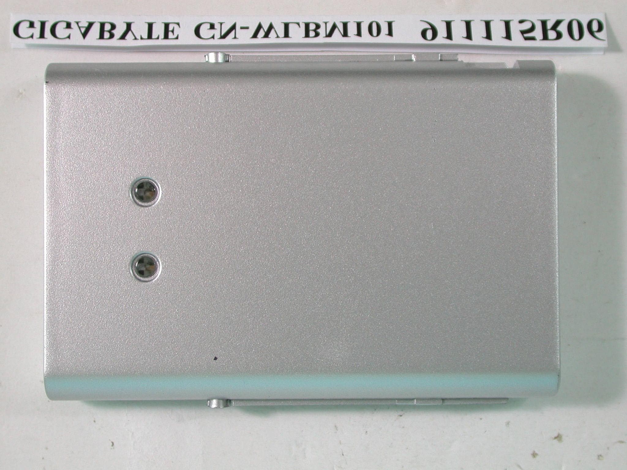
Click to zoom
Application Details
- Equipment Class
- DTS - Digital Transmission System
- Date of Grant
- Dec 17, 2002
- Application Purpose
- Original Equipment
- Date of Application
- Dec 17, 2002
- Equipment Note
- 11Mbps USB Wireless LAN Adapter
- Frequency Range
- 2412.00000000 - 2462.00000000
- Country
- Taiwan
Documents & Files
Document Text
Text extracted from the exhibit documents filed with the FCC. Open a document above to read the original.
Users Manual
GN-WLBM101 IEEE 802.11b Wireless USB Network Adapter User’s Manual http://www.gigabyte.com.tw Rev. 1.0 First Edition Contents CHAPTER 1. PRODUCT OVERVIEW..........................................................................................1 1-1. I NTRODUCTION TO THE WIRELESS LAN ADAPTER..........................................................1 1-2. F EATURES.................................................................................................................1 1-3. PHYSICAL DIMENSIONS/PACKAGING.............................................................................1 1-4. LED I NDICATING LIGHT...............................................................................................2 1-5. SYSTEM REQUIREMENTS............................................................................................2 1-5-1. Supported Platform.........................................................................................................2 1-5-2. Supported Operation System........................................................................................2 CHAPTER 2. INSTALLING THE WIRELESS LAN ADAPTER................................................3 2-1. INSTALLING THE DRIVER & UTILITY (APPLICABLE TO ANY SUPPORTED OS) .....................3 CHAPTER 3. USING THE UTILITY...............................................................................................6 3-1. INFO.........................................................................................................................6 3-2. STATISTICS .............................................................................................7 3-3. CONFIGURATION .......................................................................................8 3-4. ENCRYPTION.............................................................................................................8 3-5. ADVANCED .............................................................................................9 3-6. PROFILES .............................................................................................10 3-7. ABOUT ................................................................................................11 CHAPTER 4. SPECIFICATIONS.................................................................................................12 1 Chapter 1. Product Overview 1-1. Introduction to The Wireless LAN Adapter This wireless LAN (Local Area Network) adapter is composed of the IEEE 802.11b MAC, Baseband, and radio components, USB interface, and two built-in antennas. This product adopts the direct sequence spread spectrum (DSSS) technology and the DBPSK, DQPSK, and CCK modulation mode to provide a very stable wireless communication quality and an excellent signal receiver capability. Our product features the compact size, low power consumption, and power management functions, and provides a high-speed wireless data communication. Therefore, our product is ideally suitable for being integrated into the personal mobile and desktop platform. 1-2. Features Conforms to IEEE 802.11b specification. Transmits data rate up to the maximum speed of 11Mbps. Dynamically scales the data rate to 11, 5.5, 2, and 1Mbps. Automatic power management to reduce battery consumption. Built-in diversity antenna. Supports 64-bit /128-bit WEP encryption. Driver supports Windows 98/98SE/Me and Windows2000/XP. 1-3. Physical Dimensions/Packaging Dimensions: 89.2mm * 62mm * 14.5mm This wireless LAN adapter conforms to the USB1.1 Mechanical standard. There are two LED-indicating lights to indicate power/Link status. 2 1-4. LED Indicating Light Power: The Power LED lights up when the USB wireless LAN adapter is powered on. Link: The Link LED lights up when the adapter has an active connection. If the LED isn’t on, the adapter isn’t interfacing with the network. 1-5. System Requirements 1-5-1. Supported Platform IBM PC/AT compatible computer 1-5-2. Supported Operation System Windows 98/98SE/Me Windows 2000/XP 3 Chapter 2. Installing the Wireless LAN Adapter 2-1. Installing The Driver & Utility (Applicable to any supported OS) Step 1: Please make sure that you don’t plug your USB adapter yet. Step 2: Insert our setup CD into your CDROM drive, the following window will pop up. Step 3: Click “Install Wireless LAN Driver”. Step 4: Click “Next”.
Users Manual
4 Step 5: Click “Yes”. The wizard will ask you to click the type of setup. Step 6: Select “Typical” and then click “Next”. The wizard will ask you to provide the destination path of where the application will be installed. 5 Step 7: You can click “Browse” to set the path or simply only click “Next” to go on. Step 8: Click “Finish”, and then your installation is ok. 6 Chapter 3. Using The Utility The Configuration & Monitor Utility is a powerful application that helps you to configure the Fast-VNET card and monitor the statistics of the communication. Unlike the standard method of configuring the adapter via the operating system utilities (e.g. Control Panel), this application permits the dynamic modification of the configuration parameters while the adapter is operating. It also offers some more configuration options. Gigabyte offers the Configuration & Monitor Utility for Windows 98/98SE/Me, and Windows 2000/XP. It appears as an icon on the system tray of Windows every time the adapter is running (see Figure 3-1). You can open it by double-clicking on this icon. Figure 3-1. The icon of the Configuration & Monitor Utility Note: Please keep in mind that the Configuration & Monitor Utility can be used to change the above configuration parameters when the adapter is active. When the adapter is not in use, please use the Control Panel method. 3-1. Info The Info tab shows you the current link status of the wireless LAN adapter and the reachable assess points and the wireless LAN adapter. In the middle of the screen there is information about the status of the communication (the BSSID of the access point to which the adapter is associated, signal strength, and link quality). Figure 3-2. Current link status of the wireless LAN adapter 7 Other items in the table are the detailed information about the link status, which are available only when the wireless LAN adapter is connected to an access point or other wireless LAN adapter. SSID: Network name. BSSID: MAC address of the base station. Channel: The current channel used by the wireless LAN adapter. TxRate: The current transmission rate used by the wireless LAN adapter. Reachable Access Points / Stations: This item will show you all of the 802.11 access points or wireless LAN adapters in your wireless environment. The icon in the front of every item represents an access point or a wireless LAN adapter. You can add a network easily by clicking on the desired SSID. Signal: It shows the signal intensity of the currently connected base station. Ch: The current channel used by the wireless LAN adapter. 3-2. Statistics This option shows you to view the available statistic information (Data Packets, Management Packets and Rejected Packets). In order to renew or update this list of statistics, click the “Clear” button. In order to exit, click the “Hide” button at the bottom of the screen. Figure 3-3. Statistic information available 8 3-3. Configuration A typical screen of the application in Infrastructure mode is shown in Figure 3-4. The configuration parameters are shown at the top of the screen (Operating Mode, Channel, SSID, TxRate, Int. Roaming and Radio of the USB card). In order to change the configuration parameters, click the “Change” button, make your changes and then click “Submit” in order to save your changes. Figure 3-4. A typical screen of the application in Infrastructure mode 3-4. Encryption By choosing this option in any of the two modes, you can set four different WEP keys and specify which one of them to use. First, either enable or disable encryption from the appropriate “Encryption” field (see Figure 3-5 below). If you decide to use encryption, you can choose any of the available WEP keys (1 to 4). You also have the option to select the WEP mode (Mandatory/Optional). If you select “Mandatory”, then not only WEP will be used, but also any other station needs to use WEP encryption in order to establish a communication with your station. This requirement is in line with the IEEE 802.11b standard. If, on the other hand, you choose “Optional”, then your station can communicate with every other station regardless if they use WEP or not. Please keep in mind that the WEP keys must be in HEX format. Finally, you have the option to select whether Open System, Shared Key, or Auto authentication will be used. In order to take effect the changes you wish to make, click the “Submit” button at the bottom of the screen.
Users Manual
9 Figure 3-5. Encryption 3-5. Advanced By Choosing the Advanced option in any of the two modes, you can change advanced configuration settings, such as the Preamble Type, Fragmentation Threshold, and RTS/CTS Threshold (Figure 3-6). Figure 3-5 shows the default configuration for the advanced settings. The USB adapter has an auto-detection feature therefore when selecting “Auto” for the preamble type it automatically selects the Preamble Type depending on the Access Point Preamble type Note: In order to enable the Fragmentation and the RTS/CTS Threshold parameters move the slide bar with your mouse and then use the right and left arrow keys of your keyboard in order to select an exact number. 10 Figure 3-6. Advanced Settings 3-6. Profiles This option shows you to view your current profile. You can click “New” to create a custom profile. Figure 3-7. Your current profile 11 3-7. About By choosing this option, you can view basic information about the utility like the Driver, Firmware and Application Version and this adapter’s MAC address. Figure 3-7. Version information and MAC address 12 Chapter 4. Specification 4-1. System Standards IEEE 802.11b compliant, Wi-Fi compatible Host Interface USB 1.1 Modulation 1Mbps: DBPSK; 2Mbps: DQPSK; 5.5 and 11 Mbps: CCK Transmission Rate 1, 2, 5.5, 11 Mbps Operating Voltage 5V Operating Range Open space: 100 - 300m; Indoor: 30 - 100m 4-2. RF Performance Frequency Band 2.400 ~ 2.4835 GHz (subject to local regulation) Radio Technology DSSS (Direct Sequence Spread Spectrum) 11 Channels (US, Canada) 4 channels (France) Number of Channel 14 Channels (Japan) 13 Channels (Most European countries, ETSI) Output Power 19dBm @ Nominal Temp Range Receive Sensitivity - 80dBm @ 11 Mbps date rate, 8% PER Antenna Two built-in diversity antennas 4-3.Safety Regulation and Operating Environment FCC Part 15 (USA) EMC certification CE (Europe) Temperature Range Operating: 0 ~ 50 deg C, Storing: -20 ~ 65 deg C Humidity Max. 90% Non-condensing 4-4. Software Support Driver Windows 98/98SE/Me; Windows 2000/XP Roaming Supports roaming. Network Protocol TCP/IP, IPX, NetBEUI Security 64 bit WEP (128 bit WEP optional) Management Utility Monitors the network situation. 4-5. Mechanical Dimensions 89.2 x 62 x 14.5 mm Weight TBD Packaging Packaging specially used by Gigabyte. Host Interface USB Type B connector USB cable 80cm LED indicator Power and Link Federal Communication Commission Interference Statement This equipment has been tested and found to comply with the limits for a Class B digital device, pursuant to Part 15 of the FCC Rules. These limits are designed to provide reasonable protection against harmful interference in a residential installation. This equipment generates, uses and can radiate radio frequency energy and, if not installed and used in accordance with the instructions, may cause harmful interference to radio communications. However, there is no guarantee that interference will not occur in a particular installation. If this equipment does cause harmful interference to radio or television reception, which can be determined by turning the equipment off and on, the user is encouraged to try to correct the interference by one of the following measures: - Reorient or relocate the receiving antenna. - Increase the separation between the equipment and receiver. - Connect the equipment into an outlet on a circuit different from that to which the receiver is connected. - Consult the dealer or an experienced radio/TV technician for help. FCC Caution: To assure continued compliance, (example - use only shielded interface cables when connecting to computer or peripheral devices) any changes or modifications not expressly approved by the party responsible for compliance could void the user's authority to operate this equipment. This device complies with Part 15 of the FCC Rules. Operation is subject to the following two conditions: (1) This device may not cause harmful interference, and (2) this device must accept any interference received, including interference that may cause undesired operation. IMPORTANT NOTE: FCC Radiation Exposure Statement: This equipment complies with FCC radiation exposure limits set forth for an uncontrolled environment. This equipment should be installed and operated with minimum distance 20cm between the radiator & your body. This transmitter must not be co-located or operating in conjunction with any other antenna or transmitter.
Cover Letter(s)
本文件之智慧財產權屬於技嘉科技所有,未經授權,不得拷貝複製。 Record NO:APP.Rev:Issue Date:Page: 1-1 GIGA-BYTE TECHNOLOGY CO., LTD. 3F,No.766,Kung Yuan Road,Tainan City,Taiwan,R.O.C. Tel: +886-6-2828555, Fax: +886-6-2826555 FCC ID: JCK-GN-WLBM101 Federal Communications Commission Authorization and Evaluation Division Confidentiality Request Pursuant to Sections 0.457 and 0.459 of the Commission’s Rules, the Applicant hereby requests confidential treatment of information accompanying this Application as outlined below: Schematics Block Diagram The above materials contain trade secrets and proprietary information not customarily released to the public. The public disclosure of these matters might be harmful to the Applicant and provide unjustified benefits to its competitors. The Applicant understands that pursuant to Rule 0.457, disclosure of this Application and all accompanying documentation will not be made before the date of the Grant for this application. Sincerely yours, ------------------------------------------------------------------- Redtom Lin / Project Manager GIGA-BYTE TECHNOLOGY CO., LTD. e-mail: [email protected] Tel: +886-6-2828555 Fax: +886-6-2826555
Cover Letter(s)
本文件之智慧財產權屬於技嘉科技所有,未經授權,不得拷貝複製。 Record NO:APP.Rev:Issue Date:Page: 1-1 GIGA-BYTE TECHNOLOGY CO., LTD. 3F,No.766,Kung Yuan Road,Tainan City,Taiwan,R.O.C. Tel: +886-6-2828555, Fax: +886-6-2826555 POWER OF ATTORNEY To whom it may concern: We, the undersigned, GIGA-BYTE TECHNOLOGY CO., LTD. , hereby authorize Advance Data Technology Corporation (ADT) of Taiwan to act on our behalf in all matters relating to all processes required in the FCC Part 15C approval and any communication needed with the national authority. Any and all acts carried out by ADT on our behalf shall have the same effects as acts of our own. If you have any questions regarding the authorization, please don’t hesitate to contact us. Thank you! Sincerely yours, ------------------------------------------------------------------- Redtom Lin / Project Manager GIGA-BYTE TECHNOLOGY CO., LTD. e-mail: [email protected] Tel: +886-6-2828555 Fax: +886-6-2826555
External Photos
Page 1 ANNEX PHOTOGRAPHS OF EUT Page 2 Page 3 Page 4 Page 5
ID Label/Location Info
FCC ID Label Location
Internal Photos
Page 6 Page 7 Page 8 Page 9 Page 10
Operational Description
FCC ID: JCK-GN-WLBM101 ADT No.911115R06 Operational Description The transmitter of the EUT is powered by host equipment from USB port. The antenna is Printed Patch Antenna, and there is no antenna connector. Under normal use condition, the user has to keep at least 20cm separation distance between radiator and the body of the user. The other instruction, please have a look at the users manual. DSSS Information This device is Direct Sequence Spread Spectrum, the data is mixed by pseudorandom code which is an orthogonal code. The mixed data is digital modulated by BPSK and QPSK technique depends on the data rates. The CCK coding is applied for increasing the data rate, and also the processing gain will be increased. The bit rates are 1,2,5.5,11Mbps, the symbol rates are 1,1,1.375,1.375Mbps, the chip rates are always 11Mbps. So, the Chip/symbol is 11,11,8 and 8 respectively. Although is higher bit rate, the processing gain is lower than 10, but the CCK coding used in higher bit rate will provide 2.2dB coding gain.
RF Exposure Info
FCC ID: JCK-GN-WLBM101 ADT No.: 911115R06 FCC TEST REPORT REPORT NO.: RF911115R06 MODEL NO.: GN-WLBM101 ACCORDING: FCC Guidelines for Human Exposure IEEE C95.1 APPLICANT:Giga-Byte Technology Co., Ltd. ADDRESS:4/F, No. 3, Alley 6 Lane 45, Pao Shin Road, Hsin-Tien City, Taipei, Taiwan ISSUED BY:Advance Data Technology Corporation LAB LOCATION:47 14th Lin, Chiapau Tsun, Linko, Taipei, Taiwan, R.O.C. 0528 ILAC MRA Lab Code: 200102-0 FCC ID: JCK-GN-WLBM101 ADT No.: 911115R06 RF Exposure Measurement (Mobile Device) 1. Introduction 2.4 GHz frequency band is regarded specially as a dangerous band for its heating harmfulness to the human body. That’s why microwave oven is operating in this frequency band. The manufacturer whose product is working in this frequency band is obligatory to prove the harmfulness of his product. In this document, we try to prove the safety of radiation harmfulness to the human body for our product. The limit for Maximum Permissible Exposure (MPE) specified in FCC 1.1310 is followed. The Gain of the antenna used in this product is measured in a Fully Anechoic Chamber (FAC), and the maximum total power input to the antenna is measured. Through the Friis transmission formula and the maximum gain of the antenna, we can calculate the distance, away from the product, where the limit of MPE is reached. 2. Classification The antenna of the product, under normal use condition, is at least 20 cm away from the body of the user. Warning statement for keeping 20 cm separation distance and the prohibition of operating next to a person has been printed on the users manual. So, this product is classified as the Mobile Device. 3. RF Exposure Limit According to FCC 1.1310: The criteria listed in the following table shall be used to evaluate the environmental impact of human exposure to radio-frequency (RF) radiation as specified in 1.1307(b). FCC ID: JCK-GN-WLBM101 ADT No.: 911115R06 LIMITS FOR MAXIMUM PERMISSIBLE EXPOSURE (MPE) Frequency Range (MHz) Electric Field Strength (V/m) Magnetic Field Strength (A/m) Power Density (mW/cm 2 ) Average Time (minutes) (A)Limits For Occupational / Control Exposures 30-30061.40.1631.06 300-1500......F/3006 1500-100,000......56 (B)Limits For General Population / Uncontrolled Exposure 30-30027.50.0730.230 300-1500......F/150030 1500-100,000......1.030 F = Frequency in MHz 4. Friis Formula Friis transmission formula : Pd = (Pout*G) / (4*pi*r 2 ) where Pd = power density in mW/cm 2 Pout = output power to antenna in mW G = gain of antenna in linear scale Pi = 3.1416 R = distance between observation point and center of the radiator in cm Pd is the limit of MPE, 1 mW/cm 2 . If we know the maximum Gain of the antenna and the total power input to the antenna, through the calculation, we will know the distance r where the MPE limit is reached. Ref. : David K. Cheng, Field and Wave Electromagnetics, Second Edition, Page 640, Eq. (11-133). 5. EUT Operating condition The software provided by Manufacturer enabled the EUT to transmit and receive data at lowest, middle and highest channel individually. FCC ID: JCK-GN-WLBM101 ADT No.: 911115R06 6. Test Results 6.1 Antenna Gain The maximum Gain measured in Fully Anechoic Chamber is 1dBi or 1.26 (numeric). 6.2 Output Power Into Antenna & RF Exposure Distance : CHANNEL CHANNEL FREQUENCY (MHz) OUTPUT POWER TO ANTENNA (mW) MINIMUM ALLOWABLE DISTANCE ( r ) FROM SKIN (Centi-Meter) 1241287.502.96 6243773.282.71 11246271.452.68 The minimum allowable distance is very close to the enclosure of the antenna and is very far away from the human being under normal use condition.
Schematics
55 44 33 22 11 D D C C B B A A COMPANY PROPRIETARY Synthesizer - Power Amplifier BW=100MHz INTERFACE STAGE NO POP WLBM101 <RevCode> <Title> Custom 16 , 14, 2002 TitleSize Document Number Rev Date: Sheet of IFL2 IFL1 AUX VCCPA_ NETU6_12 N12969769 TX_RF_LO 2 S_CLK 3,4 GC_TX 2 E_D 2,3 VCC 2,3,5 SEL1 4 TXVGC 3 ANTSEL 3 IF_LO 2 nANTSEL 3 REF_IN 3 RX_RF_LO 2 DG_AUX 4 PREAMPIN 2 RX_IN 2 RXEN 3,4 nGS 3 GS 2,3 S_DATA 3,4 SVCC SVCC SVCC DVCC VCCPA C5568pF J2 1 23 45 SIG GNDGND GND GND R1 100 R64 36 R130 R55 10k,THERMISTOR C1415pF C6 100pF C75 22pF DIEFLAG U1 SI4126 12746 8 9 14 161821 27 28 35 10 11 12 13 15171920 22 23 24 25 26 29 GNDRGNDRGNDRGNDRGNDR GNDR GNDR GNDD GNDDGNDD GNDI SDATA GNDR NCNC RFOUT VDDR AUXOUT PWDNB XIN VDDD IFLAIFLB GNDI IFOUT VDDI SENB SCLK DI R100100 U7AS179-92 13 465 2 TX RX /RXENRXENANT GND C61 5pF L1 1.2nH C80 1nF C2122pF L510nH R514.7k R8 100 R150 C11 15pF C889pF L25.6nH L19 Ferrite Bead U2AS179-92 13 465 2 TXRX /RXEN RXEN ANT GND R63 150 C32 5pF C53100pF C2 15pF C27 15pF R1710k C2810nF C25 2pF C892.7pF C41pF R41 6.8k R6 100 C86 22pF C235pF C265pF Cp11 NP J3 MM8430-2600TB1 1 2 3 4 5 6 ANTIN ANTOUT GND GND GND GND C3 2.4pF R62150 L214.7nH C3115pF L11 ANT1 1 1 C83 10nF R7 100 C1 22pF C8715pF R65 0 C13 22pF FL4 2.450GHz 1 2 3 IN OUT GND C82100pF C9 1pF R1647K,NP Cp1 NP ANT2 1 1 U6 RF5117 1234 5 6 7 8 9101112 13 14 15 16 17 RF inVreg1gndPWRsenPSref Vreg1 Vreg2 Vreg2 NC NC RFoutRFoutRFout Vcc2 Vcc1 NC NC gnd C131 22pF C816.8pF Q5 DTA123JUA 32 1 R50 18K,NP R5218k L9 16nH C7910nF 55 44 33 22 11 D D C C B B A A WLBM101 RF Transeiver Stage BW=100MHz BW=100MHz COMPANY PROPRIETARY <Doc> <RevCode> <Title> B 26 , 14, 2002 TitleSize Document Number Rev Date: Sheet of RX_EN MXO+ NETR47_1 NETC46_2 NETC58_2 NETL14_1 N2 N5 NETC34_2 N4 NETC36_2 NETC47_1 NETC39_1 NETC63_2 MXO- N3 IFSAW1 IFSAW2 N1 N6 NETL12_2 RXPE_rd 3 VCC 1,3,5 GS 1,3 VCC 1,3,5 IF_LO 1 RX_EN 3 VREF1 3 Q_IN 3 PREAMPIN 1 RX_RF_LO 1 VCC 1,3,5 VCC 1,3,5 VCC 1,3,5 VCC 1,3,5 Q_OUT 3 E_D 1,3 I_OUT 3 VCC 1,3,5 VCC 1,3,5 RXPE_rd 3 VCC 1,3,5 VCC 1,3,5 GC_TX 1 VGC 3 VCC 1,3,5 RX_IN 1 I_IN 3 TX_RF_LO 1 JCH14 4 VCC VCC VCC C361.5pF C67 10nF L1247nH R3247 C639pF C59 15pF R56130 C47 10nF C503.9pF C73100pF FL12.450GHz 3 12 GND INOUT C58 22nF C43 1nF C68100pF C7410nF C37 22pF C54 22pF R2310K R61270 FL32.450GHz 3 1 2 GND IN OUT C48 10nF R4547 R4910 C62 22pF L6 1.5nH R44 23.7K, 1% C46 0.8pF R47 18 C344pF C45 10nF C60 10nF C513pF C72 10nF L163.9nH C39 10pF R5410 C9522pF C4022pF C57 22nF L15 27nH C70 100pF U3 RF2494 1234 5 6 7 8 9101112 13 14 15 16 17 PDVCC1VCC2MixOut- MixOut+ LO_In RxEn VCC3 GND3 Mix_In NCNC LNA_Out VCC4 GS LNA+In DieFlag C4122pF DF 33 U4 RF2948 12345678 9 10 11 12 13 14 15 16 32 31 30 29 28 27 26 25 242322212019181733 PDRX/ENRXIFBIASVCCIRX_IF_INTX_IF_INVCC9TX_GC IF_LO VCC8 VCC6 PA_OUT PA_IN VCC5 RF_LO RF_OUT RX_GC VREF1 VCC2 BW_sEL DCFBQ DCFBI VREF_BUF Q_OUT I_OUT VCC4 Q_IN Q_BYP I_IN I_BYP IF_OUT+ IF_OUT- DI R2 270 R4647 R243.9K R4 270 C52 10nF C6910nF L83.9nH C445pF L174.7nHC6510nF L1433nH FL2 TB135 123 4 567 8 123 4 567 8 C77100pF C90 5pF C76100pF R39 2.2K 55 44 33 22 11 D D C C B B A A Baseband Stage COMPANY PROPRIETARY WLBM101 <RevCode> <Title> Custom 36 , 14, 2002 TitleSize Document Number Rev Date: Sheet of NETU8_3 VGC_ MD_RDY_B MD_RDY_B VREF VREF SEL0 4 MCLK REF_IN 1 E_D 1,2 GS 1,2 S_CLK 1,4 RST 4 ANTSEL 1 Q_IN 2I_IN 2 S_DATA 1,4 TXVGC 1 MOSI 4 TX_PE 4 RX_PE 4 MCLK TX_RDY 4 VGC 2 CCA 4 TX_DATA 4 DATA_CLK 4 RX_DATA 4 BB3KCS 4 Q_OUT 2 RXEN 1,4 GS 1,2 nGS 1 wpe 4MD_RDY 4 PA_PE 4 RX_EN 2 ANTSEL 1 nANTSEL 1 RXPE_rd 2 RX_PE 4 VCC 1,2,5 VREF1 2 SEL0 4 I_OUT 2 SVCC SVCC DVCC VCC VCC DVCC R10 10 TP23TX_Q 1 C177pF R21 100 R6610 R33 10 R20 100 R111k C85 100nF R510k R14470 C1210.1uF R22 0 R3710k,NP TP21RX_I 1 Q6 DTA123JUA C4910nF C33 22pF U8RF3000 123456789 1011121314 2827262524232221201918171615 TX_PERX_PEMCLKTX_RDYRX_RDYVDDDGNDDCCALNA_CNTLTX_DATADATA_CLKRX_DATACSN_AD0CCLK VREF RESET ANTSEL TXVGC Q_OUT I_OUT GNDA VDDA Q_IN I_IN RSSI RXVGC CDOUT_SDA CDIN_ADI C7 10nF C22 22pF C29 68pF R3 NP TP22RX_Q 1 R6710 TP24TX_I 1 R38 0 C35 22pF C16 7pF C19 7pF C12 7pF U1144MHz 12 43 E/DGND Vcc Out C100 1nF C3027pF U107 SN74LVC86APW_1 123456 891011121314 7 a1a2Aob1b2Bo Co c1c2 Do d1d2 vcc GND C20 22pF R36330 R27 1k C105pF 55 44 33 22 11 D D C C B B A A MAC Controller -Digital Part MEMORY STAGE NO POP OSC_STRpin drives LEDs 0001 1 CFG1(TMS) Serial EEPROM present 11 No serial Device, No USB oscillator 10 No serial Device, USB osc. present Internal ROM Configuration External Flash Configuration CFG0(TDI) Serial FLASH present MAC General Configuration 0 EXTFL TABLE 1 NO POPULATE JTAG COMPANY PROPRIETARY WLBM101 <RevCode> <Title> Custom 46 , 14, 2002 TitleSize Document Number Rev Date: Sheet of GP1 MOSI S_DATA S_CLK SPI_CS SPI_CS XOUT RADIO_PE LFT RXDATA CCA NMOE SEL1TX_RDYSEL0 RX_PE NMWE M_D7 TX_PE NSCE MD_RDY DATA_CLK TXDATA M_D3M_D6M_D2M_D4M_D1M_D5M_D0 UXin UXout ULFT DN DP USBATT wpe M_A10 M_A5 M_A15M_A12 M_A8 M_A14 M_A7 M_A9 M_A9 M_A8 M_A5 M_A11 M_A[16..0] M_A0M_A2 M_A16 M_A14 M_A13 M_A4 M_A13M_A16 M_A15 M_A6 M_A12 M_A1 M_A0 M_A2 M_A11 M_A10 M_A6 M_A3 M_A1M_A3M_A7M_A4 M_D0M_D2M_D6M_D4M_D7M_D5M_D3M_D1 NSCENMOENMWE M_D[7..0] CFG0 MOSIS_CLK S_DATA S_DATA LIMK_ind PA_PE MOSI JCH14 S_CLK BB3KCS RST CFG0TDOntrstCFG1TCK ntrst TCK TDO CFG1 RADIO_PERX_PE 3 CCA 3 DATA_CLK 3 BB3KCS 3 S_CLK 1,3S_DATA 1,3 SEL1 1 RX_DATA 3TX_RDY 3TX_PE 3TX_DATA 3 SEL0 3 DG_AUX 1 DN 6 DP 6 USBATT 6 PWRO 6 MD_RDY 3 LINK_ind 5 MOSI 3PA_PE 3 JCH14 2 RXEN 1,3 SEL1 1 SEL0 3 BB3KCS 3 DATA_CLK 3 RX_DATA 3 TX_RDY 3 CCA 3 PWRO 6 RADIO_PE TX_PE 3 RX_PE 3 PA_PE 3 S_DATA 1,3 TX_DATA 3 S_CLK 1,3 MOSI 3 wpe 3 RST 3 RST 3 VCCS VCCS VCCS VCCS VCCS VCCSVCCS VCCS VCCS VCCS VCCS VCCS VCCS C419 10nF R448 0 R1013.3K R447 4.7K C41718pF X401 12MHz, 50ppm RX_DATA 1 JCH14 1 SEL0 1 R93.3K R429 130 X10036MHz R10210M J402MMS2_08 1357 2468 1357 2468 PA_PE 1 C115 2.2nF TX_DATA 1 RADIO_PE 1 RXEN 1 R1273.3K U104 AT25040-10SC-2.7 5 3142 678 SI nWPnCSGNDSO SCK nHOLD VCC C1090.1uF C1070.1uF C1060.1uF U102 AT…
Text truncated - open the document above for the full version.
Test Report
FCC ID: JCK-GN-WLBM101 Report No.: RF911115R061Issued: Dec. 12, 2002 FCC TEST REPORT REPORT NO.: RF911115R06 MODEL NO.: GN-WLBM101 RECEIVED: Oct. 15, 2002 TESTED: Oct. 16 ~ Dec. 2, 2002 APPLICANT:Giga-Byte Technology Co., Ltd. ADDRESS:No. 6, Bau Chiang Road, Hsin-Tien, Taiepi Hsien, Taiwan, R.O.C. ISSUED BY:Advance Data Technology Corporation LAB LOCATION:47 14th Lin, Chiapau Tsun, Linko, Taipei, Taiwan, R.O.C. This test report consists of 49 pages in total. It may be duplicated completely for legal use with the approval of the applicant. It should not be reproduced except in full, without the written approval of our laboratory. The client should not use it to claim product endorsement by CNLA, NVLAP or any government agencies. The test results in the report only apply to the tested sample. 0528 ILAC MRA Lab Code: 200102-0 FCC ID: JCK-GN-WLBM101 Report No.: RF911115R062Issued: Dec. 12, 2002 Table of Contents 1CERTIFICATION ...........................................................................................4 2SUMMARY OF TEST RESULTS...................................................................5 3GENERAL INFORMATION ...........................................................................6 3.1GENERAL DESCRIPTION OF EUT..............................................................6 3.2DESCRIPTION OF TEST MODES................................................................7 3.3GENERAL DESCRIPTION OF APPLIED STANDARDS ...............................7 3.4DESCRIPTION OF SUPPORT UNITS..........................................................8 4TEST TYPES AND RESULTS.......................................................................9 4.1CONDUCTED EMISSION MEASUREMENT ................................................9 4.1.1LIMITS OF CONDUCTED EMISSION MEASUREMENT ......................................................9 4.1.2TEST INSTRUMENTS............................................................................................................9 4.1.3TEST PROCEDURES ..........................................................................................................10 4.1.4DEVIATION FROM TEST STANDARD ................................................................................10 4.1.5TEST SETUP........................................................................................................................ 11 4.1.6EUT OPERATING CONDITIONS .........................................................................................12 4.1.7TEST RESULTS ...................................................................................................................13 4.2RADIATED EMISSION MEASUREMENT ...................................................19 4.2.1LIMITS OF RADIATED EMISSION MEASUREMENT .........................................................19 4.2.2TEST INSTRUMENTS..........................................................................................................20 4.2.3TEST PROCEDURES ..........................................................................................................21 4.2.4DEVIATION FROM TEST STANDARD ................................................................................21 4.2.5TEST SETUP........................................................................................................................22 4.2.6EUT OPERATING CONDITIONS .........................................................................................22 4.2.7TEST RESULTS ...................................................................................................................23 4.36dB BANDWIDTH MEASUREMENT ..........................................................27 4.3.1LIMITS OF 6dB BANDWIDTH MEASUREMENT .................................................................27 4.3.2TEST INSTRUMENTS.......................................................................................................…
Text truncated - open the document above for the full version.
Contact Information
Applicant
Alain Sam-Lai
Technical Contact
Advance Data Technology CorporationEllis Wu
[email protected]+886 3 327 0892
13-1, Lane 19, WenShan 3rd St · Taoyuan · Taiwan
Test Firm
Bureau Veritas CPS (H.K.) Ltd. Taoyuan BranchRichard Chen
Technical Specifications
| # | Rule Parts | Frequency Range | Power Output |
|---|---|---|---|
| 1 | 15C | 2.41 GHz - 2.46 GHz | 88.00 mW |
Other Applications from GIGA-BYTE TECHNOLOGY CO., LTD.

JCKGM-AORUSM6
Jun 26, 2023Mouse
Equipment Class
DTS - Digital Transmission System
JCKS3
Jun 26, 2023Mouse Dongle
Equipment Class
DTS - Digital Transmission System
JCK28713AIREM60
Jul 30, 2015Sapphire Blue Optical Mouse
Equipment Class
DXX - Part 15 Low Power Communication Device Transmitter
JCK287137580RX
Jul 30, 2015Wireless Receiver
Equipment Class
DXX - Part 15 Low Power Communication Device Transmitter
JCK-MSN09C01
Feb 10, 2015NFC Controller Module with Integrated Antenna
Equipment Class
DXX - Part 15 Low Power Communication Device Transmitter