JCK-GN-WLBZ101802.11b Wireless USB Adapter
GIGA-BYTE TECHNOLOGY CO., LTD.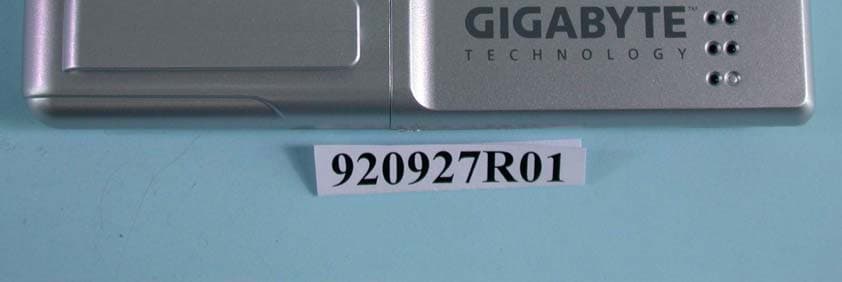
Click to zoom
Application Details
- Equipment Class
- DTS - Digital Transmission System
- Date of Grant
- Oct 30, 2003
- Application Purpose
- Original Equipment
- Date of Application
- Oct 30, 2003
- Equipment Note
- 802.11b Wireless USB Adapter
- Frequency Range
- 2412.00000000 - 2462.00000000
- Country
- Taiwan
Documents & Files
Document Text
Text extracted from the exhibit documents filed with the FCC. Open a document above to read the original.
Users Manual
GN-WLBZ101 IEEE 802.11b USB STICK Wireless LAN Card User’s Manual http://www.gigabyte.com.tw Rev. 1.0 First Edition Contents CHAPTER 1. PRODUCT OVERVIEW1 1-1. INTRODUCTION TO THE WIRELESS LAN CARD............................................................. 1 1-2. FEATURES................................................................................................................. 1 1-3. PHYSICAL DIMENSIONS/PACKAGING............................................................................ 1 1-4. LED INDICATING LIGHTS............................................................................................ 2 1-5. SYSTEM REQUIREMENTS............................................................................................ 2 CHAPTER 2. INSTALLING THE WIRELESS LAN CARD4 2-1. INSTALLING THE DRIVER & UTILITY FOR PC................................................................. 4 CHAPTER 3. USING THE UTILITY ON PC6 3-1. INFO........................................................................................................................ 6 3-2. STATISTICS.............................................................................................................. 7 3-3. CONFIGURATION....................................................................................................... 7 3-4. ENCRYPTION............................................................................................................ 8 3-5. ADVANCED............................................................................................................... 9 3-6. ABOUT................................................................................................................... 10 3-7. ACCESS POINT....................................................................................................... 10 CHAPTER 4. SPECIFICATION13 1 Chapter 1. Product Overview 1-1. Introduction to The Wireless LAN Card This wireless Local Area Network (LAN) card is composed of the IEEE 802.11b MAC with USB STICK interface、Baseband、radio components and two built-in antennas。This product adopts the direct sequence spread spectrum (DSSS) technology using the DBPSK、 DQPSK、and CCK modulations to provide a very stable wireless communication quality and an excellent signal receiver capability。 This product features the compact size、low power consumption and power management functions and provides a high-speed wireless data communication。Therefore this product is ideally suitable for being integrated into the personal mobile and handheld platform。 1-2. Features ! Two dimenional rotation of maximum 180 degree ! Conforms to IEEE 802.11b specification. ! Transmits data rate up to the maximum speed of 11Mbps. ! Dynamically scales the data rate to 11, 5.5, 2, and 1Mbps. ! Host Interface USB ! Built-in diversity antenna. ! Supports 64-bit /128-bit WEP encryption. ! Driver supports Windows 98SE/Me/2000/XP. ! Supports Software Access Point 1-3. Physical Dimensions/Packaging Dimensions: 109mm* 25mm* 16mm Before the installation procedures, please ensure the components are not damaged during the shipping. The shipment of the GN-WLBZ101 includes: One GN-WLBZ101 Wireless LAN Card One Installation CD (including User’s Guide and Driver) One User Guide Please contact your local distributor or authorized reseller immediately for any missing or damaged components. If you require returning the damaged product, you must pack it in the original packing material or the warranty will be voided. 2 1-4. LED Indicating Lights This wireless LAN card conforms to the USB standard. There are six LED-indicating lights One indicates Power status. One indicates Link status and the others indicate the intensity of received signals. Power: This LED is continuously on while the card is powered on. Link: Blinking Slow The card is scanning the network. Continuously On The card is successfully connected to a network. Blinking Quickly The data is being transmitted/received LED Light Condition of the Receiver PowerLink Intensity of received signals: This LED specifies the four conditions of “POOR”, “FAIR”, “GOOD”, and “EXCELLENT” . LED Light Condition of the Receiver POORFAIRGOODEXCELLENT 1-5. System Requirements 1-5-1. Supported Platform: IBM PC/AT compatible computer 1-5-2. Supported Operation System: Windows 98SE/Me/2000/XP 1-5-3. Software Access Point Supported Operation System: Windows 2000/XP 3 4 Chapter 2. Installing the Wireless LAN Card 2-1. Installing The Driver & Utility for PC Step 1: Please make sure that you don’t plug your card yet. Step 2: Execute the setup.exe on our CD, and then the following window will pop up. Click “Install Wireless LAN Driver”. Step 3: Click “Yes”. Step 4: Please plug-in your “Gigabyte WLAN card device” ! and will install the device driver Click “Yes”, and then your installation is ok. 5 6 Chapter 3. Using The Utility on PC The Configuration & Monitor Utility is a powerful application that helps you to configure the card and monitor the statistics of the communication link. Unlike the standard method of configuring the card via the operating system utilities (e.g. Control Panel), this application permits the dynamic modification of the configuration parameters while the card is operating. It also offers some more configuration options. It appears as an icon on the Windows system tray whenever the card is running (see Figure 3-1). The icon can tell you the received signal strength by four small green lights. You can open it by double-clicking on this icon. Figure 3-1. The icon of the Configuration & Monitor Utility WLAN Mode AP Mode 3-1. Info The Info tab shows you the current Link States of the Wireless LAN Card and the Reachable Assess Points and the Wireless LAN Card(see Figure 3-2). Figure 3-2. Current link states of the wireless LAN card Network Information:There are three states of a Wireless LAN Card: 1. Connected to Access Point: The wireless LAN card is now connecting to an Access Point. 2. Connected to Ad Hoct: The …
Text truncated - open the document above for the full version.
Cover Letter(s)
American Telecommunications Certification Body Inc. 6731 Whittier Ave, McLean, VA 22101 ` October 20, 2003 RE: Giga-Byte Technology Co., Ltd. FCC ID: JCK-GN-WLBZ101 After a review of the submitted information, I have a few comments on the above referenced Application. General 1) Please provide a higher resolution exhibit for the labeling. The FCC ID can not be clearly read. 2) Given this is a USB "pen" style device, a 20 cm separation distance is not applicable. Please remove reference to this in the Operational Description Exhibit. 3) Test configuration photographs appear to only show the EUT positioned in a Horizontal Plane. Since the device incorporates a swivel type of base, please confirm that TX antenna for the device was checked while positioned in both a Horizontal and Vertical position for worse case positioning. There is concern with the EUT positioned in the Horizontal Plane, that the major radiation pattern may have been in the z-axis. 4) FYI, because 20 cm is not an applicable distance for this type of device, the MPE exhibit provided was not reviewed. SAR 5) The Dipole calibration certificate appears more than 1 year old. Was the most recent calibration certificate included. Please explain. 6) Please provide a Z-axis scan for the worse case result. Timothy R. Johnson Examining Engineer mailto: [email protected] The items indicated above must be submitted before processing can continue on the above referenced application. Failure to provide the requested information may result in application termination. Correspondence should be considered part of the permanent submission and may be viewed from the Internet after a Grant of Equipment Authorization is issued. Please do not respond to this correspondence using the email reply button. In order for your response to be processed expeditiously, you must submit your documents through the AmericanTCB.com website. Also, please note that partial responses increase processing time and should not be submitted. Any questions about the content of this correspondence should be directed to the sender.
Cover Letter(s)
Dear Tim: The dipole calibrated period is 2 years. So that the next calibrated date is Sept. 26 2004. About the Z-axis scan plot ,I have revise the appendix a data. Thank you for your kind assistance. Best Regards, Stephanie Hung (¬xºkÁ ̈) Advance Data Technology Corporation ( ̧Û«H¬ì§Þ) Tel: 886-3 327 0910 Ext. 1668 Fax: 886-3 327 0892 e-mail: [email protected] \(^o^)/ \(^o^)/ \(^o^)/ \(^o^)/ \(^o^)/ \(^o^)/ \(^o^)/ \ (^o^)/ ----- Âà§eªÌ Stephanie Hung/ADT ©ó 2003/10/31 ¤W¤È 12:28 ----- "Timothy R. Johnson" ¦¬¥ó¤H¡G [email protected], [email protected] <tjohnson@America °Æ¥»§Û° e¡G nTCB.com> ¥D¦®¡G Review of Giga-Byte Technology Co., Ltd., FCC ID: JCK-GN-WLBZ101 2003/10/21 ¤W¤È 11:44 Ellis, Attached are comments regarding review of this application. Thank You, Timothy R. Johnson NARTE Certified EMC Engineer No. EMC-002205-NE Subject: =?Big5?B? wuCxSKFHIFJldmlldyBvZiBHaWdhLUJ5dGUgVGVjaG5vbG9neSBDby4sIEx0ZA==?= =?Big5?B?LiwgRkNDIElEOiAgIEpDSy1HTi1XTEJaMTAx?= To: "Timothy R. Johnson" <[email protected]> 10/31/2003file://C:\DOCUME~1\TIMOTH~1.JOH\LOCALS~1\Temp\eud87.htm email: [email protected] alternate email: [email protected] (See attached file: ATCB Comments_102003.pd =Big5BQVRDQiBDb21tZW50c18xMDIwMDMucGRm=4.pdf 10/31/2003file://C:\DOCUME~1\TIMOTH~1.JOH\LOCALS~1\Temp\eud87.htm
Cover Letter(s)
Dear Tim: Could you please check again. About the comment three, we tested in three position, and the vertical is the worst one, so we show the vertical data in the report, but the photo taken by different engineer, so that's why we show the wrong photo. So I did revised the test report and test setup. And about the comment six, we revised the SAR report. Thank you for your kind assistance. Best Regards, Stephanie Hung (æ ́ªæ¦è‡) Advance Data Technology Corporation (èª ä¿¡ç§‘æŠ€) 10/31/2003file://C:\DOCUME~1\TIMOTH~1.JOH\LOCALS~1\Temp\eud104.htm
External Photos
Page 1 CONSTRUCTION PHOTOS OF EUT Page 2 Page 3 Page 4
ID Label/Location Info
1 (1266x617x16M jpeg)圖圖
Internal Photos
Page 1 CONSTRUCTION PHOTOS OF EUT Page 2 Page 3
Operational Description
FCC ID: JCK-GN-WLBZ101 ADT No.RF920927R01 Operational Description The transmitter of the EUT is powered by host equipment. The antenna type is Patch antenna with no connector. The other instruction, please have a look at the users manual. DSSS Information This device is Direct Sequence Spread Spectrum, the data is mixed by pseudorandom code which is an orthogonal code. The mixed data is digital modulated by BPSK and QPSK technique depends on the data rates. The CCK coding is applied for increasing the data rate, and also the processing gain will be increased. The bit rates are 1,2,5.5,11Mbps, the symbol rates are 1,1,1.375,1.375Mbps, the chip rates are always 11Mbps. So, the Chip/symbol is 11,11,8 and 8 respectively. Although is higher bit rate, the processing gain is lower than 10, but the CCK coding used in higher bit rate will provide 2.2dB coding gain.
RF Exposure Info
FCC ID: JCK-GN-WLBZ101 Report No.: SA920927R011Issued: Oct 09 th 2003 SAR TEST REPORT REPORT NO.: SA920927R01 MODEL NO.: GN-WLBZ101 RECEIVED: Oct. 01 2003 TESTED: Oct. 08 2003 APPLICANT: GIGA-BYTE TECHNOLOGY CO., LTD. ADDRESS: No. 6, Bau Chiang Road, Hsin-Tien, Taipei Hsien, Taiwan, ROC ISSUED BY: Advance Data Technology Corporation LAB LOCATION: 47 14th Lin, Chiapau Tsun, Linko, Taipei, Taiwan, R.O.C. This test report consists of 30 pages in total except Appendix. It may be duplicated completely for legal use with the approval of the applicant. It should not be reproduced except in full, without the written approval of our laboratory. The client should not use it to claim product endorsement by CNLA, NVLAP or any government agencies. The test results in the report only apply to the tested sample. FCC ID: JCK-GN-WLBZ101 Report No.: SA920927R012Issued: Oct 09 th 2003 Table of Contents 1.CERTIFICATION ........................................................................................................................3 2.GENERAL INFORMATION ........................................................................................................4 2.1GENERAL DESCRIPTION OF EUT ..........................................................................................4 2.2GENERAL DESCRIPTION OF APPLIED STANDARDS ...........................................................5 2.3GENERAL INOFRMATION OF THE SAR SYSTEM..................................................................5 2.4 GENERAL DESCRIPTION OF THE SPATIAL PEAK SAR EVALUATION .................................9 3.DESCRIPTION OF TEST MODES AND CONFIGURATIONS ................................................13 4.DESCRIPTION OF SUPPORT UNITS ....................................................................................14 5.TEST RESULTS.......................................................................................................................15 5.1TEST PROCEDURES..............................................................................................................15 5.2MEASURED SAR RESULT .....................................................................................................16 5.3SAR LIMITS .............................................................................................................................17 5.4RECIPES FOR TISSUE SIMULATING LIQUIDS ....................................................................17 5.5TEST EQUIPMENT FOR TISSUE PROPERTY ......................................................................19 6.SYSTEM VALIDATION ............................................................................................................20 6.1TEST EQUIPMENT..................................................................................................................20 6.2TEST PROCEDURE ................................................................................................................20 6.3VALIDATION RESULT .............................................................................................................22 6.4SYSTEM VALIDATION UNCERTAINTIES...............................................................................23 7.MEASUREMENT SAR PROCEDURE UNCERTAINTIES .......................................................24 7.1PROBE CALIBRATION UNCERTAINTY .................................................................................24 7.2ISOTROPY UNCERTAINTY ....................................................................................................24 7.3BOUNDARY EFFECT UNCERTAINTY....................................................................................25 7.4PROBE LINEARITY UNCERTAINTY.......................................................................................25 7.5READOUT ELECTRONICS UNCERTAINTY...........................................................................25 7.6RESPONSE TIME UNCERTAINTY .........................................................................................26 7.7INTEGRATION TIME UNCERTAINTY .....................................................................................27 7.8PROBE POSITIONER MECHANICAL TOLERANCE..............................................................27 7.9PROBE POSITIONING ............................................................................................................28 7.10 PHANTOM UNCERTAINTY .....................................................................................................28 7.11 DASY4 UNCERTAINTY BUDGET ...........................................................................................29 8.INFORMATION ON THE TESTING LABORATORIES ............................................................30 APPENDIX A: TEST CONFIGURATIONS AND TEST DATA APPENDIX B: ADT SAR MEASUREMENT SYSTEM APPENDIX C: PHOTOGRAPHS OF SYSTEM VALIDATION APPENDIX D: SYSTEM CERTIFICATE & CALIBRATION FCC ID: JCK-GN-WLBZ101 Report No.: SA920927R013Issued: Oct 09 th 2003 1. CERTIFICATION PRODUCT : IEEE 802.11b Wireless USB Adapter MODEL NO. : GN-WLBZ101 BRAND NAME : GIGABYTE APPLICANT : GIGA-BYTE TECHNOLOGY CO., LTD TEST ITEM: ENGINEERING SAMPLE STANDARDS : 47 CFR Part 2 (Section 2.1093), FCC OET Bulletin 65, Supplement C (01-01), RSS-102 We, Advance Data Technology Corporation, hereby certify that one sample of the designation has been tested in our facility on 09 th Oct. 2003. The test record, data evaluation and Equipment Under Test (EUT) configurations represented herein are true and accurate, and it was tested according to the standards listed above. This device was found to be in compliance with the Specific Absorption Rate (SAR) requirement specified in FCC part 2.1093 under General Population / Uncontrolled Exposure condition. FCC ID: JCK-GN-WLBZ101 Report No.: SA920927R014Issued: Oct 09 th 2003 2. GENERAL INFORMATION 2.1 GENERAL DESCRIPTION OF EUT PRODUCT IEEE 802.11b Wireless USB Adapter MODEL NO. GN-WLBZ101 POWER SUPPLY 5VDC powered by host equipment CL…
Text truncated - open the document above for the full version.
RF Exposure Info
APPENDIX B: ADT SAR MEASUREMENT SYSTEM APPENDIX C: PHOTOGRAPHS OF SYSTEM VALIDATION APPENDIX D: SYSTEM CERTIFICATE & CALIBRATION D1: SAM PHANTOM D2: 2450MHZ SYSTEM VALIDATION DIPOLE D3: DOSIMETRIC E-FIELD PROBE
Test Report
FCC ID: JCK-GN-WLBZ101 Report No.: RF920927R011Issued: October 11, 2003 FCC TEST REPORT REPORT NO.: RF920927R01 MODEL NO.: GN-WLBZ101 RECEIVED: September 27, 2003 TESTED: September 18 ~ September 22, 2003 APPLICANT: GIGA-BYTE TECHNOLOGY CO., LTD. ADDRESS: No. 6, Bau Chiang Road, Hsin-Tien, Taipei Hsien, Taiwan, R.O.C. ISSUED BY: Advance Data Technology Corporation LAB LOCATION: 47 14th Lin, Chiapau Tsun, Linko, Taipei, Taiwan, R.O.C. This test report consists of 49 pages in total. It may be duplicated completely for legal use with the approval of the applicant. It should not be reproduced except in full, without the written approval of our laboratory. The client should not use it to claim product endorsement by CNLA, NVLAP or any government agencies. The test results in the report only apply to the tested sample. 0528 ILAC MRA Lab Code: 200102-0 FCC ID: JCK-GN-WLBZ101 Report No.: RF920927R012Issued: October 11, 2003 Table of Contents 1CERTIFICATION ........................................................................................... 4 2SUMMARY OF TEST RESULTS ................................................................... 5 3GENERAL INFORMATION............................................................................ 6 3.1GENERAL DESCRIPTION OF EUT .............................................................. 6 3.2DESCRIPTION OF TEST MODES ................................................................ 7 3.3GENERAL DESCRIPTION OF APPLIED STANDARDS ............................... 7 3.4DESCRIPTION OF SUPPORT UNITS .......................................................... 8 3.5CONFIGURATION OF SYSTEM UNDER TEST........................................... 8 4TEST TYPES AND RESULTS ....................................................................... 9 4.1CONDUCTED EMISSION MEASUREMENT ................................................ 9 4.1.1LIMITS OF CONDUCTED EMISSION MEASUREMENT .............................. 9 4.1.2TEST INSTRUMENTS .................................................................................. 9 4.1.3TEST PROCEDURES ................................................................................. 10 4.1.4DEVIATION FROM TEST STANDARD ....................................................... 10 4.1.5TEST SETUP .............................................................................................. 11 4.1.6EUT OPERATING CONDITIONS ................................................................ 11 4.1.7TEST RESULTS .......................................................................................... 12 4.2RADIATED EMISSION MEASUREMENT ................................................... 18 4.2.1LIMITS OF RADIATED EMISSION MEASUREMENT ................................. 18 4.2.2TEST INSTRUMENTS ................................................................................ 19 4.2.3TEST PROCEDURES ................................................................................. 20 4.2.4DEVIATION FROM TEST STANDARD ....................................................... 20 4.2.5TEST SETUP .............................................................................................. 21 4.2.6EUT OPERATING CONDITIONS ................................................................ 21 4.2.7.TEST RESULTS .......................................................................................... 22 4.36dB BANDWIDTH MEASUREMENT........................................................... 27 4.3.1LIMITS OF 6dB BANDWIDTH MEASUREMENT........................................ 27 4.3.2TEST INSTRUMENTS ................................................................................ 27 4.3.3TEST PROCEDURE ................................................................................... 28 4.3.4DEVIATION FROM TEST STANDARD ....................................................... 28 4.3.5TEST SETUP .............................................................................................. 28 4.3.6EUT OPERATING CONDITIONS ................................................................ 28 FCC ID: JCK-GN-WLBZ101 Report No.: RF920927R013Issued: October 11, 2003 4.3.7TEST RESULTS .......................................................................................... 29 4.4MAXIMUM PEAK OUTPUT POWER .......................................................... 33 4.4.1LIMITS OF MAXIMUM PEAK OUTPUT POWER MEASUREMENT ........... 33 4.4.2TEST INSTRUMENTS ................................................................................ 33 4.4.3TEST PROCEDURES ................................................................................. 34 4.4.4DEVIATION FROM TEST STANDARD ....................................................... 34 4.4.5TEST SETUP .............................................................................................. 34 4.4.6EUT OPERATING CONDITIONS ................................................................ 34 4.4.7TEST RESULTS .......................................................................................... 35 4.5POWER SPECTRAL DENSITY MEASUREMENT ...................................... 36 4.5.1LIMITS OF POWER SPECTRAL DENSITY MEASUREMENT ................... 36 4.5.2TEST INSTRUMENTS ................................................................................ 36 4.5.3TEST PROCEDURE ................................................................................... 37 4.5.4DEVIATION FROM TEST STANDARD ....................................................... 37 4.5.5TEST SETUP .............................................................................................. 37 4.5.6EUT OPERATING CONDITIONS ................................................................ 37 4.5.7TEST RESULTS .......................................................................................... 38 4.6BAND EDGES MEASUREMENT ................................................................ 42 4.6.1LIMITS OF BAND EDGES MEASUREMENT.................................…
Text truncated - open the document above for the full version.
Test Setup Photos
FCC ID: JCK-GN-WLBZ101 Report No.: RF920927R0147Issued: October 11, 2003 5 PHOTOGRAPHS OF THE TEST CONFIGURATION CONDUCTED EMISSION TEST FCC ID: JCK-GN-WLBZ101 Report No.: RF920927R0148Issued: October 11, 2003 RADIATED EMISSION TEST
Contact Information
Applicant
Alain Sam-Lai
Technical Contact
Advance Data Technology CorporationEllis Wu
[email protected]+886-3-327-0910
13-1, Lane 19, WenShan 3rd., St. · Taoyuan · Taiwan
Non-Technical Contact
Advance Data Technology CorporationEllis Wu
[email protected]+886-3-327-0910
Test Firm
Bureau Veritas CPS (H.K.) Ltd. Taoyuan BranchTommy Wu
Technical Specifications
| # | Rule Parts | Frequency Range | Power Output |
|---|---|---|---|
| 1 | 15C | 2.41 GHz - 2.46 GHz | 50.00 mW |
Other Applications from GIGA-BYTE TECHNOLOGY CO., LTD.

JCKGM-AORUSM6
Jun 26, 2023Mouse
Equipment Class
DTS - Digital Transmission System
JCKS3
Jun 26, 2023Mouse Dongle
Equipment Class
DTS - Digital Transmission System
JCK28713AIREM60
Jul 30, 2015Sapphire Blue Optical Mouse
Equipment Class
DXX - Part 15 Low Power Communication Device Transmitter
JCK287137580RX
Jul 30, 2015Wireless Receiver
Equipment Class
DXX - Part 15 Low Power Communication Device Transmitter
JCK-MSN09C01
Feb 10, 2015NFC Controller Module with Integrated Antenna
Equipment Class
DXX - Part 15 Low Power Communication Device Transmitter