JCK-GN-WLCM201Compact Flash WLAN Card
GIGA-BYTE TECHNOLOGY CO., LTD.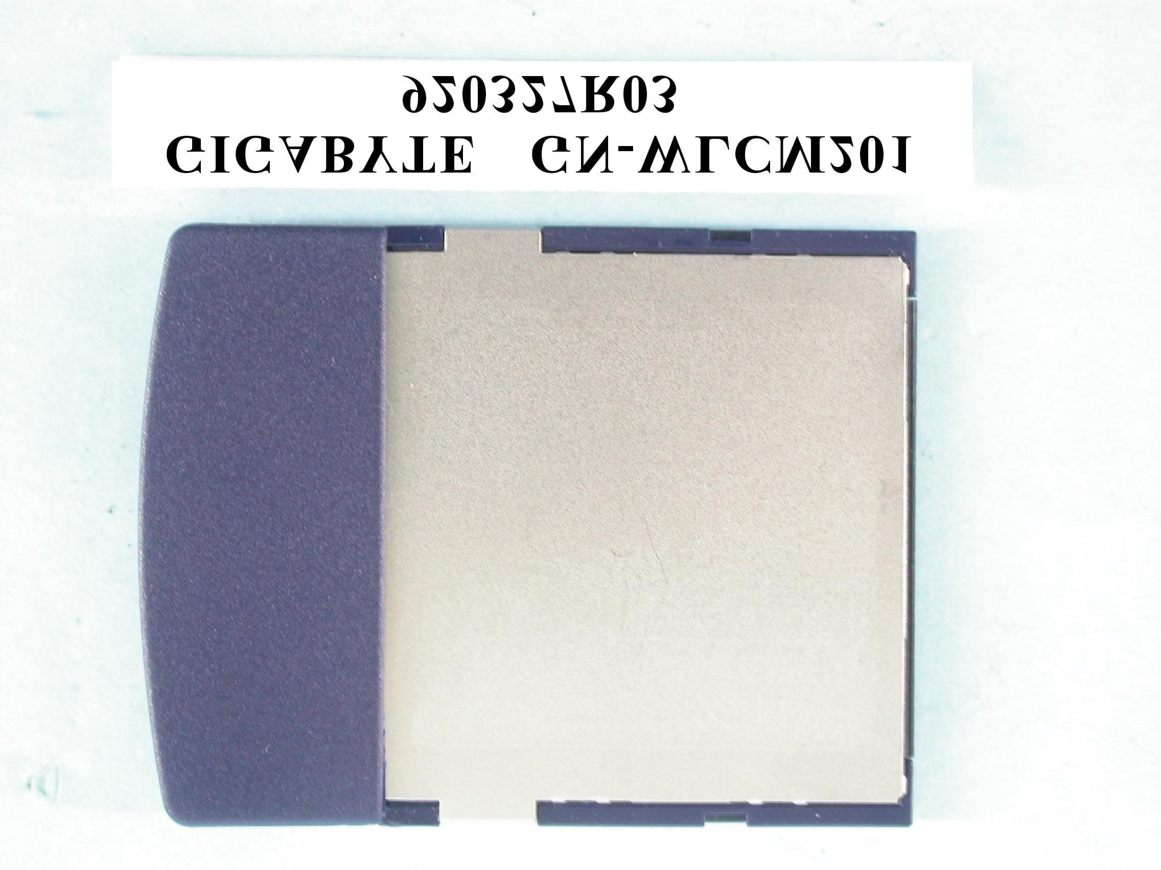
Click to zoom
Application Details
- Equipment Class
- DTS - Digital Transmission System
- Date of Grant
- Apr 13, 2003
- Application Purpose
- Original Equipment
- Date of Application
- Apr 13, 2003
- Equipment Note
- Compact Flash WLAN Card
- Frequency Range
- 2412.00000000 - 2462.00000000
- Country
- Taiwan
Documents & Files
Document Text
Text extracted from the exhibit documents filed with the FCC. Open a document above to read the original.
Users Manual
GN-WLCM201 IEEE 802.11b Compact Flash Wireless LAN Card User’s Manual http://www.gigabyte.com.tw Rev. 1.0 First Edition Contents CHAPTER 1. PRODUCT OVERVIEW..........................................................................................1 1-1. INTRODUCTION TO THE WIRELESS LAN CARD...............................................................1 1-2. F EATURES.................................................................................................................1 1-3. P HYSICAL DIMENSIONS/PACKAGING.............................................................................1 1-4. LED I NDICATING LIGHT...............................................................................................2 1-5. S YSTEM REQUIREMENTS............................................................................................2 1-5-1. Supported Platform.........................................................................................................2 1-5-2. Supported Operation System........................................................................................2 CHAPTER 2. INSTALLING THE WIRELESS LAN CARD........................................................3 2-1. I NSTALLING THE DRIVER & UTILITY ............................................................................3 CHAPTER 3. SPECIFICATIONS...................................................................................................5 Chapter 1. Product Overview 1-1. Introduction to The Wireless LAN Card This wireless Local Area Network (LAN) card is composed of the IEEE 802.11b MAC with CompactFlash interface, Baseband, radio components, and two built-in antennas. This product adopts the direct sequence spread spectrum (DSSS) technology using the DBPSK, DQPSK, and CCK modulations to provide a very stable wireless communication quality and an excellent signal receiver capability. This product features the compact size, low power consumption, and power management functions, and provides a high-speed wireless data communication. Therefore, this product is ideally suitable for being integrated into the personal mobile and handheld platform. 1-2. Features Conforms to IEEE 802.11b specification. Transmits data rate up to the maximum speed of 11Mbps. Dynamically scales the data rate to 11, 5.5, 2, and 1Mbps. Automatic power management to reduce battery consumption. Built-in diversity antenna. Supports 64-bit /128-bit WEP encryption. Driver supports Windows CE3.0/4.1 and Windows 98SE/Me/2000/XP. 1-3. Physical Dimensions/Packaging Dimensions: 55.4mm* 43mm* 3.3mm This wireless LAN card conforms to the Compact Flash Type I standard. There is one LED-indicating lights to indicate Act/Link status. 1 1-4. LED Indicating Light Scanning: This LED blinks quickly when the card is scanning a network. Associated: This LED is continuously on while the card is linked with the network. 1-5. System Requirements 1-5-1. Supported Platform IBM PC/AT compatible computer 1-5-2. Supported Operation System Windows CE3.0/4.1 Windows 98SE/Me Windows 2000/XP 2 Chapter 2. Installing the Wireless LAN Card 2-1. Installing The Driver & Utility Step 1: Please make sure that you don’t plug your card yet. Step 2: Execute the setup.exe on our CD, and then the following window will pop up. Step 3: Click “Next”. Step 4: Click “OK”. 3 Step 5: Click “Finish”, and then your installation is ok. 4 Chapter 3. Specification System Standards IEEE 802.11b Host Interface Compact Flash (CF)Type I Modulation 1Mbps: DBPSK; 2Mbps: DQPSK; 5.5 and 11 Mbps: CCK Data Rate 1, 2, 5.5, 11 Mbps Operating Voltage 3.3V Power Tx 250mA; Rx 200 mA; Sleep 40 mA Operating Range Open space: 100 - 300m; Indoor: 30 - 100m RF Frequency Band 2.400 ~ 2.484 GHz (subject to local regulation) Radio Technology DSSS (Direct Sequence Spread Spectrum) 11 Channels (US, Canada) 4 channels (France) Number of Channel 14 Channels (Japan) 13 Channels (Most European countries, ETSI) Output power 13 dBm@ Nominal Temp Range Receive Sensitivity Minimum - 80dBm@11 Mbps date rate; Typical –82dBm@11 Mbps date rate Regulatory and Environmental Compliance FCC part 15 (USA) EMC certification CE (Europe) Temperature Range Operating: 0 ~ 55 degree C, Storage: -20 ~ 65 degree C Humidity Max. 90% Non-condensing Software Driver Windows CE 3.0/4.1; Windows 98/ME/2000/XP Roaming Full mobility and seamless roaming Security 64 and 128 bit WEP Management Utility Link Configuration for network join and statistics Mechanical Dimensions 55.4mm * 43mm * 3.3mm Weight 16 ± 1 g Packaging Generic, Gigabyte, private labeling optional LED indicator Power/Link status 5 Federal Communication Commission Interference Statement This equipment has been tested and found to comply with the limits for a Class B digital device, pursuant to Part 15 of the FCC Rules. These limits are designed to provide reasonable protection against harmful interference in a residential installation. This equipment generates, uses and can radiate radio frequency energy and, if not installed and used in accordance with the instructions, may cause harmful interference to radio communications. However, there is no guarantee that interference will not occur in a particular installation. If this equipment does cause harmful interference to radio or television reception, which can be determined by turning the equipment off and on, the user is encouraged to try to correct the interference by one of the following measures: - Reorient or relocate the receiving antenna. - Increase the separation between the equipment and receiver. - Connect the equipment into an outlet on a circuit different from that to which the receiver is connected. - Consult the dealer or an experienced radio/TV technician for help. FCC Caution: To assure continued compliance, (example - use only shielded interface cables when connecting to computer or peripheral devices) any changes or modifications not expressly approved by the party responsible for compliance could void the us…
Text truncated - open the document above for the full version.
Cover Letter(s)
本文件之智慧財產權屬於技嘉科技所有,未經授權,不得拷貝複製。 Record NO:APP.Rev:Issue Date:Page: 1-1 GIGA-BYTE TECHNOLOGY CO., LTD. 3F,No.766,Kung Yuan Road,Tainan Hsien,Taiwan,R.O.C. Tel: +886-6-2828555, Fax: +886-6-2826555 FEDERAL COMMUNICATIONS COMMISSION DECLARATION OF CONFORMITY (DoC) For the following equipment: Product Name: IEEE 802.11b Compact Flash Wireless Lan Card Model No.: GN-WLCM201 Trade Name: GIGABYTE Is herewith confirmed to be in compliance with the requirements of ANSI C63.4 & FCC part 15 regulations. The test result has been shown in the ADT test report with number RF920327R03. And this compliance is subject to the following two conditions: This device may not cause harmful interference and, This device must accept any interference received, including interference that may cause undesired operation. The following local Manufacturer/Importer is responsible for this declaration: G.B.T. INC (Company Name) 17358 RAILROAD ST. CITY OF INDUSTRY, CA 91748 (Company Address) TEL: ( 626 ) 854-9338 FAX: ( 626 ) 854-9339 ERIC LU / GENERAL MANAGER (Name) / (Title) / 04-07-03 (Signature) / (Date)
Cover Letter(s)
American Telecommunications Certification Body Inc. 6731 Whittier Ave, McLean, VA 22101 April 14, 2003 RE: FCC ID: JCK-GN-WLCM201 Attention: Ellis Wu I have a few comments on this Application. 1 FYI – no action needed. Please note that this is a portable device as well as being able to be used in a PCMCIA slot with an adapter. MPE is only valid for the mobile application and is not an appropriate method to determine rf exposure in the portable configuration. However, since this device is under 25mW it can be used within 2.5cm of the Body in a portable configuration without SAR testing. A statement explaining this is all that is needed. 2 FYI – no action needed. Since the Compact Flash profile is typically for the purpose of use in devices like PDAs etc, testing should be performed in its typical use as well as in the Lap top. 3 The manual should describe the typical use of the CF card. The understood ‘typical’ use of this type form factor is for PDA and other CF I/0 protocol devices. The manual, while mentioning a Windows CE platform, does not mention use in a PDA using this platform. The MPE report also specifically mentions it is a portable device – i.e. PDA use. This explanation should instruct the user in how to install the program etc for the PDA or other Windows CE device. Please explain why this typical use of this device in a PDA has not been mentioned. 4 Dennis Ward mailto:[email protected] The items indicated above must be submitted before processing can continue on the above referenced application. Failure to provide the requested information may result in application termination. Correspondence should be considered part of the permanent submission and may be viewed from the Internet after a Grant of Equipment Authorization is issued. Please do not respond to this correspondence using the email reply button. In order for your response to be processed expeditiously, you must submit your documents through the AmericanTCB.com website. Also, please note that partial responses increase processing time and should not be submitted. Any questions about the content of this correspondence should be directed to the sender.
External Photos
Page 1 ANNEX PHOTOGRAPHS OF EUT
ID Label/Location Info
FCC ID LABEL LOCATION
Internal Photos
Page 2 Page 3 Page 4
Operational Description
FCC ID: JCK-GN-WLCM201 ADT No.920327R03 Operational Description The transmitter of the EUT (IEEE 802.11b Compact Flash Wireless Lan Card) is powered by host equipment. The antenna type is chip antenna without antenna connector. The other instruction, please have a look at the users manual. DSSS Information This device is Direct Sequence Spread Spectrum, the data is mixed by pseudorandom code which is an orthogonal code. The mixed data is digital modulated by BPSK and QPSK technique depends on the data rates. The CCK coding is applied for increasing the data rate, and also the processing gain will be increased. The bit rates are 1,2,5.5,11Mbps, the symbol rates are 1,1,1.375,1.375Mbps, the chip rates are always 11Mbps. So, the Chip/symbol is 11,11,8 and 8 respectively. Although is higher bit rate, the processing gain is lower than 10, but the CCK coding used in higher bit rate will provide 2.2dB coding gain.
RF Exposure Info
FCC ID: JCK-GN-WLCM201 ADT No.: 920327R03 FCC TEST REPORT REPORT NO.: RF920327R03 MODEL NO.: GN-WLCM201 ACCORDING: FCC Guidelines for Human Exposure IEEE C95.1 APPLICANT:GIGA-BYTE TECHNOLOGY CO., LTD. ADDRESS:No. 6, Bau Chiang Road, Hsin-Tien, Taiepi Hsien, Taiwan, R.O.C. ISSUED BY:Advance Data Technology Corporation LAB LOCATION:47 14th Lin, Chiapau Tsun, Linko, Taipei, Taiwan, R.O.C. 0528 ILAC MRA Lab Code: 200102-0 FCC ID: JCK-GN-WLCM201 ADT No.: 920327R03 RF Exposure Measurement (Portable Device) 1. Introduction 2.4GHz frequency band is regarded specially as a dangerous band for its heating harmfulness to the human body. That’s why microwave oven is operating in this frequency band. The manufacturer whose product is working in this frequency band is obligatory to prove the harmfulness of his product. In this document, we try to prove the safety of radiation harmfulness to the human body for our product. The limit for Maximum Permissible Exposure (MPE) specified in FCC 1.1310 is followed. The Gain of the antenna used in this product is measured in a Fully Anechoic Chamber (FAC), and the maximum total power input to the antenna is measured. Through the Friis transmission formula and the maximum gain of the antenna, we can calculate the distance, away from the product, where the limit of MPE is reached. 2. RF Exposure Limit According to FCC 1.1310: The criteria listed in the following table shall be used to evaluate the environmental impact of human exposure to radio-frequency (RF) radiation as specified in 1.1307(b). FCC ID: JCK-GN-WLCM201 ADT No.: 920327R03 LIMITS FOR MAXIMUM PERMISSIBLE EXPOSURE (MPE) Frequency Range (MHz) Electric Field Strength (V/m) Magnetic Field Strength (A/m) Power Density (mW/cm 2 ) Average Time (minutes) (A)Limits For Occupational / Control Exposures 30-30061.40.1631.06 300-1500......F/3006 1500-100,000......56 (B)Limits For General Population / Uncontrolled Exposure 30-30027.50.0730.230 300-1500......F/150030 1500-100,000......1.030 F = Frequency in MHz 3. Friis Formula Friis transmission formula : Pd = (Pout*G) / (4*pi*r 2 ) where Pd = power density in mW/cm 2 Pout = output power to antenna in mW G = gain of antenna in linear scale Pi = 3.1416 R = distance between observation point and center of the radiator in cm Pd is the limit of MPE, 1 mW/cm 2 . If we know the maximum Gain of the antenna and the total power input to the antenna, through the calculation, we will know the distance r where the MPE limit is reached. Ref. : David K. Cheng, Field and Wave Electromagnetics, Second Edition, Page 640, Eq. (11-133). 4. EUT Operating condition The software provided by Manufacturer enabled the EUT to transmit and receive data at lowest, middle and highest channel individually. FCC ID: JCK-GN-WLCM201 ADT No.: 920327R03 5. Test Results 5.1 Antenna Gain The maximum Gain measured in Fully Anechoic Chamber is 0dBi or 1 (numeric). 5.2 Output Power Into Antenna & RF Exposure Distance : CHANNEL CHANNEL FREQUENCY (MHz) OUTPUT POWER TO ANTENNA (mW) MINIMUM ALLOWABLE DISTANCE ( R ) FROM SKIN (Centi-Meter) 1241221.681.31 6243721.431.31 11246222.131.33 The minimum allowable distance is very close to the enclosure of the antenna and is very far away from the human being under normal use condition.
Test Report
FCC ID: JCK-GN-WLCM201 Report No.: RF920327R03 1 Issued: Apr. 4, 2003 FCC TEST REPORT REPORT NO.: RF920327R03 MODEL NO.: GN-WLCM201 RECEIVED: Mar. 27, 2003 TESTED: Mar. 31 ~ Apr. 3, 2003 APPLICANT:GIGA-BYTE TECHNOLOGY CO., LTD. ADDRESS:No. 6, Bau Chiang Road, Hsin-Tien, Taiepi Hsien, Taiwan, R.O.C. ISSUED BY:Advance Data Technology Corporation LAB LOCATION:47 14th Lin, Chiapau Tsun, Linko, Taipei, Taiwan, R.O.C. This test report consists of 48 pages in total. It may be duplicated completely for legal use with the approval of the applicant. It should not be reproduced except in full, without the written approval of our laboratory. The client should not use it to claim product endorsement by CNLA, NVLAP or any government agencies. The test results in the report only apply to the tested sample. 0528 ILAC MRA Lab Code: 200102-0 FCC ID: JCK-GN-WLCM201 Report No.: RF920327R03 2 Issued: Apr. 4, 2003 Table of Contents 1CERTIFICATION ..................................................................................................................... 4 2SUMMARY OF TEST RESULTS ............................................................................................ 5 3GENERAL INFORMATION ..................................................................................................... 6 3.1GENERAL DESCRIPTION OF EUT ....................................................................................... 6 3.2DESCRIPTION OF TEST MODES ......................................................................................... 7 3.3GENERAL DESCRIPTION OF APPLIED STANDARDS ........................................................ 7 3.4DESCRIPTION OF SUPPORT UNITS ................................................................................... 8 4TEST TYPES AND RESULTS ................................................................................................ 9 4.1CONDUCTED EMISSION MEASUREMENT ......................................................................... 9 4.1.1LIMITS OF CONDUCTED EMISSION MEASUREMENT....................................................... 9 4.1.2TEST INSTRUMENTS ............................................................................................................ 9 4.1.3TEST PROCEDURES...........................................................................................................10 4.1.4DEVIATION FROM TEST STANDARD................................................................................. 10 4.1.5TEST SETUP .........................................................................................................................11 4.1.6EUT OPERATING CONDITIONS ..........................................................................................11 4.1.7TEST RESULT ...................................................................................................................... 12 4.2RADIATED EMISSION MEASUREMENT............................................................................. 18 4.2.1LIMITS OF RADIATED EMISSION MEASUREMENT .......................................................... 18 4.2.2TEST INSTRUMENTS ..........................................................................................................19 4.2.3TEST PROCEDURES...........................................................................................................20 4.2.4DEVIATION FROM TEST STANDARD................................................................................. 20 4.2.5TEST SETUP ........................................................................................................................ 21 4.2.6EUT OPERATING CONDITIONS ......................................................................................... 21 4.2.7TEST RESULT ...................................................................................................................... 22 4.36dB BANDWIDTH MEASUREMENT .................................................................................... 26 4.3.1LIMITS OF 6dB BANDWIDTH MEASUREMENT ................................................................. 26 4.3.2TEST INSTRUMENTS ..........................................................................................................26 4.3.3TEST PROCEDURE .............................................................................................................27 4.3.4DEVIATION FROM TEST STANDARD................................................................................. 27 4.3.5TEST SETUP ........................................................................................................................ 27 4.3.6EUT OPERATING CONDITIONS ......................................................................................... 27 4.3.7TEST RESULT ...................................................................................................................... 28 4.4MAXIMUM PEAK OUTPUT POWER.................................................................................... 32 4.4.1LIMITS OF MAXIMUM PEAK OUTPUT POWER MEASUREMENT .................................... 32 4.4.2TEST INSTRUMENTS ..........................................................................................................32 4.4.3TEST PROCEDURES...........................................................................................................33 4.4.4DEVIATION FROM TEST STANDARD................................................................................. 33 4.4.5TEST SETUP ........................................................................................................................ 33 4.4.6EUT OPERATING CONDITIONS ......................................................................................... 33 4.4.7TEST RESULT ...................................................................................................................... 34 4.5POWER SPECTRAL DENSITY MEASUREMENT ............................................................... 35 4.5.1LIMI…
Text truncated - open the document above for the full version.
Test Setup Photos
FCC ID: JCK-GN-WLCM201 Report No.: RF920327R03 46 Issued: Apr. 4, 2003 5 PHOTOGRAPHS OF THE TEST CONFIGURATION CONDUCTED EMISSION TEST FCC ID: JCK-GN-WLCM201 Report No.: RF920327R03 47 Issued: Apr. 4, 2003 RADIATED EMISSION TEST
Contact Information
Applicant
Alain Sam-Lai
Technical Contact
Advance Data Technology CorporationEllis Wu
[email protected]886-3-327-0910
13-1, Lane19, WenShan 3rd ., St · Taoyuan · Taiwan
Test Firm
Bureau Veritas CPS (H.K.) Ltd. Taoyuan BranchRichard Chen
Technical Specifications
| # | Rule Parts | Frequency Range | Power Output |
|---|---|---|---|
| 1 | 15C | 2.41 GHz - 2.46 GHz | 22.10 mW |
Other Applications from GIGA-BYTE TECHNOLOGY CO., LTD.

JCKGM-AORUSM6
Jun 26, 2023Mouse
Equipment Class
DTS - Digital Transmission System
JCKS3
Jun 26, 2023Mouse Dongle
Equipment Class
DTS - Digital Transmission System
JCK28713AIREM60
Jul 30, 2015Sapphire Blue Optical Mouse
Equipment Class
DXX - Part 15 Low Power Communication Device Transmitter
JCK287137580RX
Jul 30, 2015Wireless Receiver
Equipment Class
DXX - Part 15 Low Power Communication Device Transmitter
JCK-MSN09C01
Feb 10, 2015NFC Controller Module with Integrated Antenna
Equipment Class
DXX - Part 15 Low Power Communication Device Transmitter