JCK-GN-WLMR101802.11b Cardbus Wireless LAN Card
GIGA-BYTE TECHNOLOGY CO., LTD.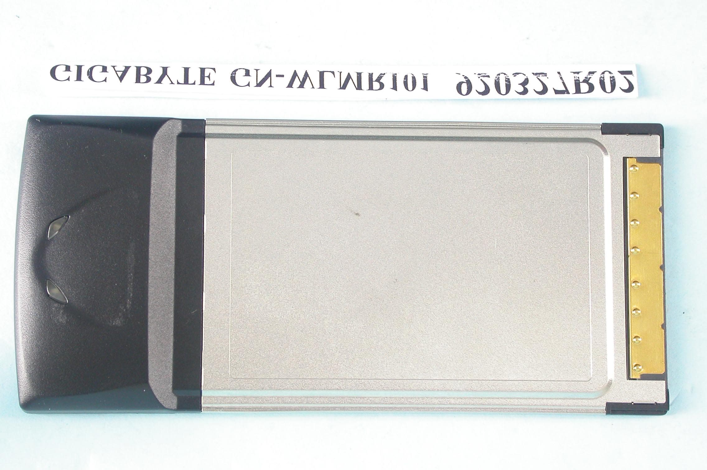
Click to zoom
Application Details
- Equipment Class
- DTS - Digital Transmission System
- Date of Grant
- May 13, 2003
- Application Purpose
- Original Equipment
- Date of Application
- May 13, 2003
- Equipment Note
- 802.11b Cardbus Wireless LAN Card
- Frequency Range
- 2412.00000000 - 2462.00000000
- Country
- Taiwan
Documents & Files
Document Text
Text extracted from the exhibit documents filed with the FCC. Open a document above to read the original.
Users Manual
GN-WLMR101 IEEE 802.11b Cardbus Wireless LAN Card User’s Manual http://www.gigabyte.com.tw Rev. 1.0 First Edition Contents CHAPTER 1. PRODUCT OVERVIEW..........................................................................................1 1-1. INTRODUCTION TO THE WIRELESS LAN CARD...............................................................1 1-2. F EATURES.................................................................................................................1 1-3. PHYSICAL DIMENSIONS/PACKAGING.............................................................................1 1-4. LED INDICATING LIGHT...............................................................................................2 1-5. S YSTEM REQUIREMENTS............................................................................................2 1-5-1. Supported Platform.........................................................................................................2 1-5-2. Supported Operation System........................................................................................2 CHAPTER 2. INSTALLING THE WIRELESS LAN CARD........................................................3 2-1. INSTALLING THE DRIVER & UTILITY ............................................................................3 CHAPTER 3. USING THE UTILITY...............................................................................................5 3-1. C ONFIGURATION........................................................................................................7 3-2. Advance Configuration .............................................................................7 3-3. STATUS ...................................................................................................8 3-4. STATISTICS...............................................................................................................9 3-5. ABOUT ..................................................................................................9 CHAPTER 4. SPECIFICATIONS.................................................................................................11 1 Chapter 1. Product Overview 1-1. Introduction to The Wireless LAN Card This wireless Local Area Network (LAN) card is composed of the IEEE 802.11b MAC with CARDBUS interface, Baseband, radio components, and two built-in antennas. This product adopts the direct sequence spread spectrum (DSSS) technology using the DBPSK, DQPSK, and CCK modulations to provide a very stable wireless communication quality and an excellent signal receiver capability. This product features the compact size, low power consumption, and power management functions, and provides a high-speed wireless data communication. Therefore, this product is ideally suitable for being integrated into the personal mobile and handheld platform. 1-2. Features Conforms to IEEE 802.11b specification. Transmits data rate up to the maximum speed of 11Mbps. Dynamically scales the data rate to 11, 5.5, 2, and 1Mbps. Automatic power management to reduce battery consumption. Built-in diversity antenna. Supports 64-bit /128-bit WEP encryption. Driver supports Windows 98SE/Me and Windows2000/XP. 1-3. Physical Dimensions/Packaging Dimensions: 118mm * 54mm * 5mm This wireless LAN card conforms to the PC card Type II standard. There are two LED-indicating lights to indicate Act/Link status. 2 1-4. LED Indicating Light Link: The Link LED lights up when the adapter has an active connection. If the LED isn’t on, the adapter isn’t interfacing with the network. Act: Blinking of the Act LED indicates that both transmit and receive activity is occurring. 1-5. System Requirements 1-5-1. Supported Platform IBM PC/AT compatible computer 1-5-2. Supported Operation System Windows 98SE/Me Windows 2000/XP 3 Chapter 2. Installing the Wireless LAN Card 2-1. Installing The Driver & Utility Step 1: Please make sure that you don’t plug your card yet. Step 2: Insert our setup CD into your CDROM drive, the following window will pop up. Step 3: Click “Install Wireless LAN Driver”. Step 4: Click “Next”. 4 Step 5: Insert your wireless LAN card, wait a moment, and then the following window will pop up. Step 6: Click “Yes”. Step 7: Click “OK”. Step 8: Click “OK”, and then your installation is ok. 5 Chapter 3. Using The Utility The Configuration & Monitor Utility is a powerful application that helps you to configure the card and monitor the statistics of the communication. Unlike the standard method of configuring the card via the operating system utilities (e.g. Control Panel), this application permits the dynamic modification of the configuration parameters while the card is operating. It also offers some more configuration options. It appears as an icon on the system tray of Windows every time the card is running (see Figure 3-1). Figure 3-1. The icon of the Configuration & Monitor Utility If this is your first time to use this card, you must start our utility and try to connect to any available wireless networks. You can open it by double-clicking on this icon, the following window will pop up. Figure 3-2. Search for available wireless networks After this card finds all available wireless networks, the following window will pop up. 6 Figure 3-3. All available wireless networks You can choose any available network and click “Connect” to join it. If this network had built a security mechanism, you must to enter a correct security key (eg. WEP) before click “Connect”. If you don’t know which network to join, or you want to configure and monitor your network, you can click “Advanced” to go into the following window. Figure 3-4. Configuration 7 Signal Strength: It shows the received signal strength from the detected wireless device. Signal Quality: It shows the quality of communication between the wireless LAN card and the associated network (In Figure 3-4, it mean linksys-11g). 3-1. Configuration The “Config” Tab contains several fields where operating paramet…
Text truncated - open the document above for the full version.
Cover Letter(s)
本文件之智慧財產權屬於技嘉科技所有,未經授權,不得拷貝複製。 Record NO:APP.Rev:Issue Date:Page: 1-1 GIGA-BYTE TECHNOLOGY CO., LTD. 3F,No.766,Kung Yuan Road,Tainan Hsien,Taiwan,R.O.C. Tel: +886-6-2828555, Fax: +886-6-2826555 FEDERAL COMMUNICATIONS COMMISSION DECLARATION OF CONFORMITY (DoC) For the following equipment: Product Name: IEEE 802.11b Cardbus Wireless LAN Card Model No.: GN-WLMR101 Trade Name: GIGABYTE Is herewith confirmed to be in compliance with the requirements of ANSI C63.4 & FCC part 15 regulations. The test result has been shown in the ADT test report with number RF920327R02. And this compliance is subject to the following two conditions: This device may not cause harmful interference and, This device must accept any interference received, including interference that may cause undesired operation. The following local Manufacturer/Importer is responsible for this declaration: G. B . T. I N C (Company Name) 17358 RAILROAD ST. CITY OF INDUSTRY, CA 91748 (Company Address) TEL: ( 626 ) 854-9338 FAX: ( 626 ) 854-9339 ERIC LU / GENERAL MANAGER (Name) / (Title) /04 -07-03 (Signature) / (Date)
Cover Letter(s)
American Telecommunications Certification Body Inc. 6731 Whittier Ave, McLean, VA 22101 April 14, 2003 RE: FCC ID: JCK-GN-WLMR101_ATCB000376 Attention: Ellis Wu I have a few comments on this Application. 1. Please note that any device over 100mW either in conducted or EIRP power such as this requires SAR testing in three hosts. The patch antenna has a gain that puts the EIRP of this device over the 100mW limitation. Please provide SAR data showing compliance in three laptops. These laptops need to be different models from each other. 2. Dennis Ward mailto:[email protected] The items indicated above must be submitted before processing can continue on the above referenced application. Failure to provide the requested information may result in application termination. Correspondence should be considered part of the permanent submission and may be viewed from the Internet after a Grant of Equipment Authorization is issued. Please do not respond to this correspondence using the email reply button. In order for your response to be processed expeditiously, you must submit your documents through the AmericanTCB.com website. Also, please note that partial responses increase processing time and should not be submitted. Any questions about the content of this correspondence should be directed to the sender.
Cover Letter(s)
American Telecommunications Certification Body Inc. 6731 Whittier Ave, McLean, VA 22101 May 14, 2003 RE: FCC ID: JCK-GN-WLMR101_ATCB000376 Attention: Ellis Wu I have a few comments on this Application. 1. Please note that any device over 100mW either in conducted or EIRP power such as this requires SAR testing in three hosts. The patch antenna has a gain that puts the EIRP of this device over the 100mW limitation. Please provide SAR data showing compliance in three laptops. These laptops need to be different models from each other. Answer - Device power is being lowered to 56mW. No SAR in three hosts needed. 2. Dennis Ward mailto:[email protected] The items indicated above must be submitted before processing can continue on the above referenced application. Failure to provide the requested information may result in application termination. Correspondence should be considered part of the permanent submission and may be viewed from the Internet after a Grant of Equipment Authorization is issued. Please do not respond to this correspondence using the email reply button. In order for your response to be processed expeditiously, you must submit your documents through the AmericanTCB.com website. Also, please note that partial responses increase processing time and should not be submitted. Any questions about the content of this correspondence should be directed to the sender.
External Photos
Page 1 ANNEX PHOTOGRAPHS OF EUT Page 2
RF Exposure Info
FCC ID: JCK-GN-WLMR101 Report No.: SA920327R02 1 Issued: April. 14 th 2003 SAR TEST REPORT REPORT NO.: SA920327R02 MODEL NO.: GN-WLMR101 RECEIVED: April. 07, 2003 TESTED: April. 07, 2003 APPLICANT:GIGA-BYTE TECHNOLOGY CO., LTD. ADDRESS:No. 6, Bau Chiang Road, Hsin-Tien, Taiepi Hsien, Taiwan, R.O.C. ISSUED BY:Advance Data Technology Corporation LAB LOCATION:47 14th Lin, Chiapau Tsun, Linko, Taipei, Taiwan, R.O.C. This test report consists of 15 pages in total except Appendix. It may be duplicated completely for legal use with the approval of the applicant. It should not be reproduced except in full, without the written approval of our laboratory. The client should not use it to claim product endorsement by CNLA, NVLAP or any government agencies. The test results in the report only apply to the tested sample. FCC ID: JCK-GN-WLMR101 Report No.: SA920327R02 2 Issued: April. 14 th 2003 Table of Contents 1.CERTIFICATION .................................................................................................................3 2.GENERAL INFORMATION ................................................................................................. 4 2.1GENERAL DESCRIPTION OF EUT ................................................................................... 4 2.2GENERAL DESCRIPTION OF APPLIED STANDARDS .................................................... 4 2.3GENERAL INOFRMATION OF THE SAR SYSTEM .......................................................... 5 2.4GENERAL DESCRIPTION OF THE PROBE SCAN RULE................................................ 7 3.DESCRIPTION OF TEST MODES AND CONFIGURATIONS ........................................... 8 4.DESCRIPTION OF SUPPORT UNITS ............................................................................... 9 5.TEST RESULTS................................................................................................................ 10 5.1TEST PROCEDURES....................................................................................................... 10 5.2MEASURED SAR RESULT .............................................................................................. 10 5.3SAR LIMITS ...................................................................................................................... 11 5.4EUT CONDUCTED POWER VARIATION ........................................................................ 11 5.5TISSUE ............................................................................................................................. 12 5.6TEST EQUIPMENT FOR TISSUE PROPERTY ............................................................... 12 6.SYSTEM VALIDATION...................................................................................................... 13 7.MEASUREMENT UNCERTAINTIES ................................................................................ 14 8.INFORMATION ON THE TESTING LABORATORIES ..................................................... 15 APPENDIX A: TEST CONFIGURATIONS AND TEST DATA APPENDIX B: ADT SAR MEASUREMENT SYSTEM APPENDIX C: PHOTOGRAPHS OF SYSTEM VALIDATION APPENDIX D: SYSTEM CERTIFICATE & CALIBRATION FCC ID: JCK-GN-WLMR101 Report No.: SA920327R02 3 Issued: April. 14 th 2003 1. CERTIFICATION PRODUCT : IEEE 802.11b Cardbus Wireless LAN Card MODEL NO. : GN-WLMR101 BRAND NAME : GIGABYTE APPLICANT : GIGA-BYTE TECHNOLOGY CO. , LTD. STANDARDS : 47 CFR Part 2 (Section 2.1093), FCC OET Bulletin 65, Supplement C (01-01), RSS-102 We, Advance Data Technology Corporation, hereby certify that one sample of the designation has been tested in our facility on 07 th April. 2003. The test record, data evaluation and Equipment Under Test (EUT) configurations represented herein are true and accurate, and it was tested according to the standards listed above. This device was found to be in compliance with the Specific Absorption Rate (SAR) requirement specified in FCC part 2.1093 under General Population / Uncontrolled Exposure condition. FCC ID: JCK-GN-WLMR101 Report No.: SA920327R02 4 Issued: April. 14 th 2003 2. GENERAL INFORMATION 2.1 GENERAL DESCRIPTION OF EUT PRODUCTIEEE 802.11b Cardbus Wireless LAN Card MODEL NO.GN-WLMR101 POWER SUPPLY3.3VDC powered by host equipment CLASSIFICATIONPortable device, production unit MODULATION TYPE BPSK, QPSK, CCK RADIO TECHNOLOGY DSSS TRANSFER RATE 1~11Mbps FREQUENCY RANGE2412MHz ~ 2462MHz NUMBER OF CHANNEL11 CONDUCTED OUTPUT POWER 55.59mW ANTENNA TYPEInternal Antenna PEAK SAR0.109W/kg DATA CABLENA I/O PORTSPCMCIA ASSOCIATED DEVICESNA 2.2 GENERAL DESCRIPTION OF APPLIED STANDARDS According to the specifications of the manufacturer, this product must comply with the requirements of the following standards: FCC 47 CFR Part 2 (2.1093) FCC OET Bulletin 65, Supplement C (01- 01) RSS-102 All tests have been performed and recorded as per the above standards. FCC ID: JCK-GN-WLMR101 Report No.: SA920327R02 5 Issued: April. 14 th 2003 2.3 GENERAL INOFRMATION OF THE SAR SYSTEM DASY4 (software 4.1, build 33) consists of high precision robtics system, probe alignment sensor, phantom, robot controller, controlled PC and near-field probe. The robot includes six axis that can move to the precision position of the DASY4 software defined. The DASY4 software can define the area which is detected by the probe. The robot is connected to controlled box. Controlled PC is connected to the controlled robot box. The DAE includes amplifier, signal multiplexing, AD converter, offset measurement, surface detection. It is connected to the Electro-optical coupler (ECO). The ECO performs the conversion form the optical into digital electric signal of the DAE and transfers data to the PC. ET3DV6 ISOTROPIC E-FIELD PROBE Construction Symmetrical design with triangular core. Built-in optical fiber for surface detection system. Built-in shielding against static charges. PEEK enclosure material (resistant to organic solvents, e.g., glycolether). Calibration Basic Broad Band Calibration in air: 10-2500 MHz C…
Text truncated - open the document above for the full version.
Test Report
FCC ID: JCK-GN-WLMR101 Report No.: RF920327R02 1 Issued: May 5, 2003 FCC TEST REPORT REPORT NO.: RF920327R02 MODEL NO.: GN-WLMR101 RECEIVED: Mar. 27, 2003 TESTED: Mar. 31 ~ Apr. 30, 2003 APPLICANT:GIGA-BYTE TECHNOLOGY CO., LTD. ADDRESS:No. 6, Bau Chiang Road, Hsin-Tien, Taiepi Hsien, Taiwan, R.O.C. ISSUED BY:Advance Data Technology Corporation LAB LOCATION:47 14th Lin, Chiapau Tsun, Linko, Taipei, Taiwan, R.O.C. This test report consists of 48 pages in total. It may be duplicated completely for legal use with the approval of the applicant. It should not be reproduced except in full, without the written approval of our laboratory. The client should not use it to claim product endorsement by CNLA, NVLAP or any government agencies. The test results in the report only apply to the tested sample. 0528 ILAC MRA Lab Code: 200102-0 FCC ID: JCK-GN-WLMR101 Report No.: RF920327R02 2 Issued: May 5, 2003 Table of Contents 1CERTIFICATION ..................................................................................................................... 4 2SUMMARY OF TEST RESULTS ............................................................................................ 5 3GENERAL INFORMATION ..................................................................................................... 6 3.1GENERAL DESCRIPTION OF EUT ....................................................................................... 6 3.2DESCRIPTION OF TEST MODES ......................................................................................... 7 3.3GENERAL DESCRIPTION OF APPLIED STANDARDS ........................................................ 7 3.4DESCRIPTION OF SUPPORT UNITS ................................................................................... 8 4TEST TYPES AND RESULTS ................................................................................................ 9 4.1CONDUCTED EMISSION MEASUREMENT ......................................................................... 9 4.1.1LIMITS OF CONDUCTED EMISSION MEASUREMENT....................................................... 9 4.1.2TEST INSTRUMENTS ............................................................................................................ 9 4.1.3TEST PROCEDURES...........................................................................................................10 4.1.4DEVIATION FROM TEST STANDARD................................................................................. 10 4.1.5TEST SETUP .........................................................................................................................11 4.1.6EUT OPERATING CONDITIONS ..........................................................................................11 4.1.7TEST RESULT ...................................................................................................................... 12 4.2RADIATED EMISSION MEASUREMENT............................................................................. 18 4.2.1LIMITS OF RADIATED EMISSION MEASUREMENT .......................................................... 18 4.2.2TEST INSTRUMENTS ..........................................................................................................19 4.2.3TEST PROCEDURES...........................................................................................................20 4.2.4DEVIATION FROM TEST STANDARD................................................................................. 20 4.2.5TEST SETUP ........................................................................................................................ 21 4.2.6EUT OPERATING CONDITIONS ......................................................................................... 21 4.2.7TEST RESULT ...................................................................................................................... 22 4.36dB BANDWIDTH MEASUREMENT .................................................................................... 26 4.3.1LIMITS OF 6dB BANDWIDTH MEASUREMENT ................................................................. 26 4.3.2TEST INSTRUMENTS ..........................................................................................................26 4.3.3TEST PROCEDURE .............................................................................................................27 4.3.4DEVIATION FROM TEST STANDARD................................................................................. 27 4.3.5TEST SETUP ........................................................................................................................ 27 4.3.6EUT OPERATING CONDITIONS ......................................................................................... 27 4.3.7TEST RESULT ...................................................................................................................... 28 4.4MAXIMUM PEAK OUTPUT POWER.................................................................................... 32 4.4.1LIMITS OF MAXIMUM PEAK OUTPUT POWER MEASUREMENT .................................... 32 4.4.2TEST INSTRUMENTS ..........................................................................................................32 4.4.3TEST PROCEDURES...........................................................................................................33 4.4.4DEVIATION FROM TEST STANDARD................................................................................. 33 4.4.5TEST SETUP ........................................................................................................................ 33 4.4.6EUT OPERATING CONDITIONS ......................................................................................... 33 4.4.7TEST RESULT ...................................................................................................................... 34 4.5POWER SPECTRAL DENSITY MEASUREMENT ............................................................... 35 4.5.1LIMIT…
Text truncated - open the document above for the full version.
Test Setup Photos
FCC ID: JCK-GN-WLMR101 Report No.: RF920327R02 46 Issued: Apr. 4, 2003 5 PHOTOGRAPHS OF THE TEST CONFIGURATION CONDUCTED EMISSION TEST FCC ID: JCK-GN-WLMR101 Report No.: RF920327R02 47 Issued: Apr. 4, 2003 RADIATED EMISSION TEST
Contact Information
Applicant
Alain Sam-Lai
Technical Contact
Advance Data Technology CorporationEllis Wu
[email protected]+886-3-327-0910
13-1, Lane19, WenShan 3rd ., St., · Taoyuan · Taiwan
Test Firm
Bureau Veritas CPS (H.K.) Ltd. Taoyuan BranchRichard Chen
Technical Specifications
| # | Rule Parts | Frequency Range | Power Output |
|---|---|---|---|
| 1 | 15C | 2.41 GHz - 2.46 GHz | 56.00 mW |
Other Applications from GIGA-BYTE TECHNOLOGY CO., LTD.

JCKGM-AORUSM6
Jun 26, 2023Mouse
Equipment Class
DTS - Digital Transmission System
JCKS3
Jun 26, 2023Mouse Dongle
Equipment Class
DTS - Digital Transmission System
JCK28713AIREM60
Jul 30, 2015Sapphire Blue Optical Mouse
Equipment Class
DXX - Part 15 Low Power Communication Device Transmitter
JCK287137580RX
Jul 30, 2015Wireless Receiver
Equipment Class
DXX - Part 15 Low Power Communication Device Transmitter
JCK-MSN09C01
Feb 10, 2015NFC Controller Module with Integrated Antenna
Equipment Class
DXX - Part 15 Low Power Communication Device Transmitter