JCK-GN-WLMS50211Mbps Wireless LAN Card Module
GIGA-BYTE TECHNOLOGY CO., LTD.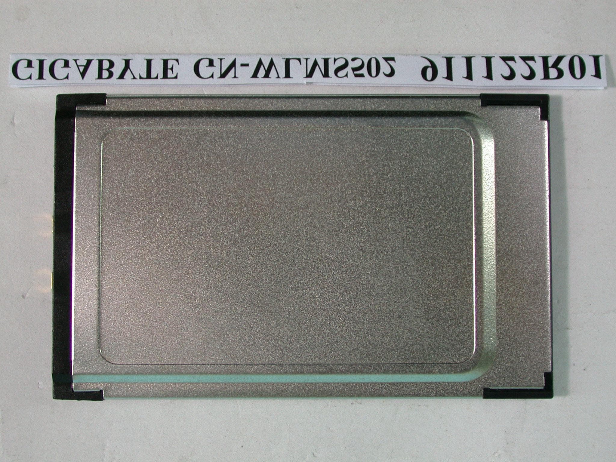
Click to zoom
Application Details
- Equipment Class
- DTS - Digital Transmission System
- Date of Grant
- Dec 18, 2002
- Application Purpose
- Original Equipment
- Date of Application
- Dec 18, 2002
- Equipment Note
- 11Mbps Wireless LAN Card Module
- Frequency Range
- 2412.00000000 - 2462.00000000
- Country
- Taiwan
Documents & Files
Document Text
Text extracted from the exhibit documents filed with the FCC. Open a document above to read the original.
Users Manual
GN-WLMS502 IEEE 802.11b PCMCIA Wireless LAN Card User’s Manual http://www.gigabyte.com.tw Rev. 1.0 First Edition Contents CHAPTER 1. PRODUCT OVERVIEW.......................................................................................... 1 1-1. INTRODUCTION TO THE WIRELESS LAN CARD.............................................................. 1 1-2. FEATURES................................................................................................................. 1 1-3. PHYSICAL DIMENSIONS/PACKAGING............................................................................ 1 CHAPTER 2. SPECIFICATIONS................................................................................................... 2 1 Chapter 1. Product Overview 1-1. Introduction to The Wireless LAN Card This wireless LAN (Local Area Network) card is composed of the IEEE 802.11b MAC, Baseband, and radio components, PCMCIA interface, and two built-in antennas. This product adopts the direct sequence spread spectrum (DSSS) technology and the DBPSK, DQPSK, and CCK modulation mode to provide a very stable wireless communication quality and an excellent signal receiver capability. Our product features the compact size, low power consumption, and power management functions, and provides a high-speed wireless data communication. Therefore, our product is ideally suitable for being integrated into Access Point, Router or Gateway and the other network products. 1-2. Features ! Conforms to IEEE 802.11b specification. ! Transmits data rate up to the maximum speed of 11Mbps. ! Dynamically scales the data rate to 11, 5.5, 2, and 1Mbps. ! Automatic power management to reduce battery consumption. ! Supports 64-bit /128-bit WEP encryption. ! Provide Tertiary 1.2.1 (AP mode firmware) for customer to build their wireless communication function. 1-3. Physical Dimensions/Packaging Dimensions: 88 mm x 54 mm x 6 mm This wireless LAN card conforms to the PC card Type II Standard. 2 Chapter 2. Specification 4-1. System StandardsIEEE 802.11b compliant, Wi-Fi compatible Host InterfacePCMCIA PC Card Type II Modulation1Mbps: DBPSK; 2Mbps: DQPSK; 5.5 and 11 Mbps: CCK Transmission Rate1, 2, 5.5, 11 Mbps Operating Voltage3.3V Operating RangeOpen space: 100 - 300m; Indoor: 30 - 100m 4-2. RF Performance Frequency Band2.400 ~ 2.4835 GHz (subject to local regulation) Radio TechnologyDSSS (Direct Sequence Spread Spectrum) 11 Channels (US, Canada)4 channels (France) Number of Channel 14 Channels (Japan)13 Channels (Most European countries, ETSI) Output Power13.5dBm @ Nominal Temp Range Receive SensitivityTypical: - 81dBm @ 11 Mbps date rate, 8% PER AntennaTwo MMCX connectors for external antenna 4-3.Safety Regulation and Operating Environment FCC Part 15 (USA) EMC certification CE (Europe) Temperature RangeOperating: 0 ~ 55 deg C, Storing: -20 ~ 65 deg C HumidityMax. 95% Non-condensing 4-4. Software Support AP mode firmwareTertiary 1.2.1 RoamingSupports roaming. Security64 bit WEP (128 bit WEP optional) 4-5. Mechanical Dimensions88 x 54 x 6 mm Weight34 g PackagingPackaging specially used by Gigabyte. 3 Federal Communication Commission Interference Statement This equipment has been tested and found to comply with the limits for a Class B digital device, pursuant to Part 15 of the FCC Rules. These limits are designed to provide reasonable protection against harmful interference in a residential installation. This equipment generates, uses and can radiate radio frequency energy and, if not installed and used in accordance with the instructions, may cause harmful interference to radio communications. However, there is no guarantee that interference will not occur in a particular installation. If this equipment does cause harmful interference to radio or television reception, which can be determined by turning the equipment off and on, the user is encouraged to try to correct the interference by one of the following measures: - Reorient or relocate the receiving antenna. - Increase the separation between the equipment and receiver. - Connect the equipment into an outlet on a circuit different from that to which the receiver is connected. - Consult the dealer or an experienced radio/TV technician for help. FCC Caution: To assure continued compliance, (example - use only shielded interface cables when connecting to computer or peripheral devices) any changes or modifications not expressly approved by the party responsible for compliance could void the user's authority to operate this equipment. This device complies with Part 15 of the FCC Rules. Operation is subject to the following two conditions: (1) This device may not cause harmful interference, and (2) this device must accept any interference received, including interference that may cause undesired operation. Statement Needed to be Shown on End Product Since this module is installed inside the end product, the end product should be affixed a label on visible area showing that this product contain a RF module, and also its FCC ID. IMPORTANT NOTE: FCC Radiation Exposure Statement: This equipment complies with FCC radiation exposure limits set forth for an uncontrolled environment. This equipment should be installed and operated with minimum distance 20cm between the radiator & your body. This transmitter must not be co-located or operating in conjunction with any other antenna or transmitter. 4 This device is intended only for OEM integrators under the following conditions: 1) The antenna must be installed such that 20 cm is maintained between the antenna and users, and 2) The transmitter module may not be co-located with any other transmitter or antenna. As long as the 2 conditions above are met, further transmitter testing will not be required. However, the OEM integrator is still responsible for testing their end-product for any additional compliance requirements required with this module installed (for example, digital device emissions, PC peripheral requirements, etc.). IMPORTANT NOTE: In the eve…
Text truncated - open the document above for the full version.
Cover Letter(s)
FCC ID: JCK-GN-WLMS502 ADT No.911122R01 Modular Approval Request Letter Advance Data Technology Dec. 12, 2002 Dear Application Examiner, GIGA-BYTE TECHNOLOGY CO., LTD’s 11Mbps Wireless LAN Card, FCC ID: JCK- GN-WLMS502, would like to have your authorization for Limited Module Approval specific to the mobile device such as Access Point, Router and Gateway. The requirements of Public Notice DA00-1407 have been met and shown on the following statements. 1. “The modular transmitter must have its own RF shielding.”: The radio portion of this module has been shielded, please see exhibition External Photo. 2. “The modular transmitter must have buffered modulation/data inputs.” The EUT has buffered data inputs, it is integrated in chip ISL3873. 3. “The modular transmitter must have its own power supply regulation.” There is a regulator in the DC input port, the part number is AME8805. 4. “The modular transmitter must comply with the antenna requirements of section 15.203 and 15.204(C).” The EUT meets the FCC antenna requirements. The spurious emission, unique antenna connector and photo of antennas are shown in the test report. 5. “The modular transmitter must be tested in a stand-alone configuration” The EUT was tested in a stand-alone configuration via a PCMCIA adapter card. Please see section Photographs of Test Configuration in the test report. 6. “The modular transmitter must be labeled with its own FCC ID number.” Please see exhibition Label Sample for the FCC ID of this module. And also in the exhibition Users Manual, there are instructions give to the OEM on how to label the end product. FCC ID: JCK-GN-WLMS502 ADT No.911122R01 7. “The modular transmitter must comply with any specific rule or operating requirements applicable to the transmitter and the manufacturer must provide adequate instructions along with the module to explain any such requirements.” The EUT is compliant with all applicable FCC rules. Detail instructions for maintaining compliance are given in the Users Manual. 8. “The modular transmitter must comply with any applicable RF exposure requirements.” The EUT is compliant with all applicable RF exposure requirements. RF Exposure is addressed in the RF exposure exhibition. Please contact me if you have any further questions. Thanks for your attention. Best Regards, Dr. Alan Lane Manager of R&TTE Division Advance Data Technology
Cover Letter(s)
本文件之智慧財產權屬於技嘉科技所有,未經授權,不得拷貝複製。 Record NO:APP.Rev:Issue Date:Page: 1-1 GIGA-BYTE TECHNOLOGY CO., LTD. 3F,No.766,Kung Yuan Road,Tainan Hsien,Taiwan,R.O.C. Tel: +886-6-2828555, Fax: +886-6-2826555 FEDERAL COMMUNICATIONS COMMISSION DECLARATION OF CONFORMITY (DoC) For the following equipment: Product Name: 11Mbps Wireless LAN Card Model No.: GN-WLMS502 Trade Name: GIGABYTE Is herewith confirmed to be in compliance with the requirements of ANSI C63.4 & FCC part 15 regulations. The test result has been shown in the ADT test report with number RF911122R01. And this compliance is subject to the following two conditions: This device may not cause harmful interference and, This device must accept any interference received, including interference that may cause undesired operation.
External Photos
Page 1 ANNEX PHOTOGRAPHS OF EUT Page 2 Page 3 Page 4 Page 5
ID Label/Location Info
FCC ID Label Location
Internal Photos
Page 6 Page 7 Page 8
Operational Description
FCC ID: JCK-GN-WLMS502 ADT No.911122R01 Operational Description The transmitter of the EUT (11Mbps Wireless LAN Card) is powered by host equipment. The antenna is Dipole antenna, and antenna connector type is MMCX. The other instruction, please have a look at the users manual. DSSS Information This device is Direct Sequence Spread Spectrum, the data is mixed by pseudorandom code which is an orthogonal code. The mixed data is digital modulated by BPSK and QPSK technique depends on the data rates. The CCK coding is applied for increasing the data rate, and also the processing gain will be increased. The bit rates are 1,2,5.5,11Mbps, the symbol rates are 1,1,1.375,1.375Mbps, the chip rates are always 11Mbps. So, the Chip/symbol is 11,11,8 and 8 respectively. Although is higher bit rate, the processing gain is lower than 10, but the CCK coding used in higher bit rate will provide 2.2dB coding gain.
RF Exposure Info
FCC ID: JCK-GN-WLMS502 ADT No.: 911122R01 FCC TEST REPORT REPORT NO.: RF911122R01 MODEL NO.: GN-WLMS502 ACCORDING: FCC Guidelines for Human Exposure IEEE C95.1 APPLICANT:Giga-Byte Technology Co., Ltd. ADDRESS:No. 6, Bau Chiang Road, Hsin-Tien, Taiepi Hsien, Taiwan, R.O.C. ISSUED BY:Advance Data Technology Corporation LAB LOCATION:47 14th Lin, Chiapau Tsun, Linko, Taipei, Taiwan, R.O.C. 0528 ILAC MRA Lab Code: 200102-0 FCC ID: JCK-GN-WLMS502 ADT No.: 911122R01 RF Exposure Measurement (Mobile Device) 1. Introduction 2.4GHz frequency band is regarded specially as a dangerous band for its heating harmfulness to the human body. That’s why microwave oven is operating in this frequency band. The manufacturer whose product is working in this frequency band is obligatory to prove the harmfulness of his product. In this document, we try to prove the safety of radiation harmfulness to the human body for our product. The limit for Maximum Permissible Exposure (MPE) specified in FCC 1.1310 is followed. The Gain of the antenna used in this product is measured in a Fully Anechoic Chamber (FAC), and the maximum total power input to the antenna is measured. Through the Friis transmission formula and the maximum gain of the antenna, we can calculate the distance, away from the product, where the limit of MPE is reached. 2. Classification The antenna of the product, under normal use condition, is at least 20 cm away from the body of the user. Warning statement for keeping 20 cm separation distance and the prohibition of operating next to a person has been printed on the users manual. So, this product is classified as the Mobile Device. 3. RF Exposure Limit According to FCC 1.1310: The criteria listed in the following table shall be used to evaluate the environmental impact of human exposure to radio-frequency (RF) radiation as specified in 1.1307(b). FCC ID: JCK-GN-WLMS502 ADT No.: 911122R01 LIMITS FOR MAXIMUM PERMISSIBLE EXPOSURE (MPE) Frequency Range (MHz) Electric Field Strength (V/m) Magnetic Field Strength (A/m) Power Density (mW/cm 2 ) Average Time (minutes) (A)Limits For Occupational / Control Exposures 30-30061.40.1631.06 300-1500......F/3006 1500-100,000......56 (B)Limits For General Population / Uncontrolled Exposure 30-30027.50.0730.230 300-1500......F/150030 1500-100,000......1.030 F = Frequency in MHz 4. Friis Formula Friis transmission formula : Pd = (Pout*G) / (4*pi*r 2 ) where Pd = power density in mW/cm 2 Pout = output power to antenna in mW G = gain of antenna in linear scale Pi = 3.1416 R = distance between observation point and center of the radiator in cm Pd is the limit of MPE, 1 mW/cm 2 . If we know the maximum Gain of the antenna and the total power input to the antenna, through the calculation, we will know the distance r where the MPE limit is reached. Ref. : David K. Cheng, Field and Wave Electromagnetics, Second Edition, Page 640, Eq. (11-133). 5. EUT Operating condition The software provided by Manufacturer enabled the EUT to transmit and receive data at lowest, middle and highest channel individually. FCC ID: JCK-GN-WLMS502 ADT No.: 911122R01 6. Test Results 6.1 Antenna Gain The maximum Gain measured in Fully Anechoic Chamber is 2.1dBi or 1.62(numeric). 6.2 Output Power Into Antenna & RF Exposure Distance : CHANNEL CHANNEL FREQUENCY (MHz) OUTPUT POWER TO ANTENNA (mW) MINIMUM ALLOWABLE DISTANCE ( r ) FROM SKIN (Centi-Meter) 1241229.651.96 6243729.111.94 11246229.111.94 The minimum allowable distance is very close to the enclosure of the antenna. So, the user has no need to worry about the harmfulness of radiation. But it is recommended to always keep, at least, 20cm separation distance with the antenna.
Test Report
FCC ID: JCK-GN-WLMS502 Report No.: RF911122R011Issued: Dec. 12, 2002 FCC TEST REPORT REPORT NO.: RF911122R01 MODEL NO.: GN-WLMS502 RECEIVED: Nov. 18, 2002 TESTED: Nov. 20 ~ Nov. 28, 2002 APPLICANT:Giga-Byte Technology Co., Ltd. ADDRESS:No. 6, Bau Chiang Road, Hsin-Tien, Taiepi Hsien, Taiwan, R.O.C. ISSUED BY:Advance Data Technology Corporation LAB LOCATION:47 14th Lin, Chiapau Tsun, Linko, Taipei, Taiwan, R.O.C. This test report consists of 52 pages in total. It may be duplicated completely for legal use with the approval of the applicant. It should not be reproduced except in full, without the written approval of our laboratory. The client should not use it to claim product endorsement by CNLA, NVLAP or any government agencies. The test results in the report only apply to the tested sample. 0528 ILAC MRA Lab Code: 200102-0 FCC ID: JCK-GN-WLMS502 Report No.: RF911122R012Issued: Dec. 12, 2002 Table of Contents 1CERTIFICATION ........................................................................................... 4 2SUMMARY OF TEST RESULTS ................................................................... 5 3GENERAL INFORMATION............................................................................ 6 3.1GENERAL DESCRIPTION OF EUT .............................................................. 6 3.2DESCRIPTION OF TEST MODES ................................................................ 7 3.3GENERAL DESCRIPTION OF APPLIED STANDARDS ............................... 7 3.4DESCRIPTION OF SUPPORT UNITS .......................................................... 8 4TEST TYPES AND RESULTS ....................................................................... 9 4.1CONDUCTED EMISSION MEASUREMENT ................................................ 9 4.1.1LIMITS OF CONDUCTED EMISSION MEASUREMENT.............................. 9 4.1.2TEST INSTRUMENTS .................................................................................. 9 4.1.3TEST PROCEDURES ................................................................................. 10 4.1.4DEVIATION FROM TEST STANDARD ....................................................... 10 4.1.5TEST SETUP .............................................................................................. 11 4.1.6EUT OPERATING CONDITIONS ................................................................ 12 4.1.7TEST RESULTS .......................................................................................... 13 4.2RADIATED EMISSION MEASUREMENT ................................................... 19 4.2.1LIMITS OF RADIATED EMISSION MEASUREMENT................................. 19 4.2.2TEST INSTRUMENTS ................................................................................ 20 4.2.3TEST PROCEDURES ................................................................................. 21 4.2.4DEVIATION FROM TEST STANDARD ....................................................... 21 4.2.5TEST SETUP .............................................................................................. 22 4.2.6EUT OPERATING CONDITIONS ................................................................ 22 4.2.7TEST RESULTS .......................................................................................... 23 4.2.8TEST RESULTS .......................................................................................... 25 4.36dB BANDWIDTH MEASUREMENT........................................................... 28 4.3.1LIMITS OF 6dB BANDWIDTH MEASUREMENT ........................................ 28 4.3.2TEST INSTRUMENTS ................................................................................ 28 4.3.3TEST PROCEDURE ................................................................................... 29 4.3.4DEVIATION FROM TEST STANDARD ....................................................... 29 4.3.5TEST SETUP .............................................................................................. 29 4.3.6EUT OPERATING CONDITIONS ................................................................ 29 4.3.7TEST RESULTS .......................................................................................... 30 4.4MAXIMUM PEAK OUTPUT POWER .......................................................... 34 4.4.1LIMITS OF MAXIMUM PEAK OUTPUT POWER MEASUREMENT ........... 34 4.4.2TEST INSTRUMENTS ................................................................................ 34 4.4.3TEST PROCEDURES ................................................................................. 35 FCC ID: JCK-GN-WLMS502 Report No.: RF911122R013Issued: Dec. 12, 2002 4.4.4DEVIATION FROM TEST STANDARD ....................................................... 35 4.4.5TEST SETUP .............................................................................................. 35 4.4.6EUT OPERATING CONDITIONS ................................................................ 35 4.4.7TEST RESULTS .......................................................................................... 36 4.5POWER SPECTRAL DENSITY MEASUREMENT ...................................... 37 4.5.1LIMITS OF POWER SPECTRAL DENSITY MEASUREMENT ................... 37 4.5.2TEST INSTRUMENTS ................................................................................ 37 4.5.3TEST PROCEDURE ................................................................................... 38 4.5.4DEVIATION FROM TEST STANDARD ....................................................... 38 4.5.5TEST SETUP .............................................................................................. 38 4.5.6EUT OPERATING CONDITIONS ................................................................ 38 4.5.7TEST RESULTS .......................................................................................... 39 4.6BAND EDGES MEASUREMENT ................................................................ 43 4.6.1LIMITS OF BAND EDGES MEASUREMENT..................................…
Text truncated - open the document above for the full version.
Test Report
FCC ID: JCK-GN-WLMS502 Report No.: RF911122R01 1 ANNEX 1. 6dB BANDWIDTH MEASUREMENT 1.1 LIMITS OF 6DB BANDWIDTH MEASUREMENT The minimum of 6dB Bandwidth Measurement is 0.5 MHz. 1.2 TEST INSTRUMENTS Description & ManufacturerModel No.Serial No.Calibrated Until SPECTRUM ANALYZERFSEK30100049July 24, 2003 NOTE: The calibration interval of the above test instruments is 12 months and the calibrations are traceable to NML/ROC and NIST/USA. FCC ID: JCK-GN-WLMS502 Report No.: RF911122R01 2 1.3 TEST PROCEDURE The transmitter output was connected to the spectrum analyzer through an attenuator. The bandwidth of the fundamental frequency was measured by spectrum analyzer with 100kHz RBW and 100kHz VBW. The 6 dB bandwidth is defined as the total spectrum the power of which is higher than peak power minus 6dB. 1.4 DEVIATION FROM TEST STANDARD No deviation 1.5 TEST SETUP For the actual test configuration, please refer to the related Item – Photographs of the Test Configuration. 1.6 EUT OPERATING CONDITIONS The software provided by client to enable the EUT under transmission condition continuously at lowest, middle and highest channel frequencies individually. EUT SPECTRUM ANALYZER FCC ID: JCK-GN-WLMS502 Report No.: RF911122R01 3 1.7 TEST RESULTS EUT 11Mbps Wireless LAN Card MODEL GN-WLMS502 DATA RATE 1Mbps INPUT POWER (SYSTEM) 120Vac, 60 Hz ENVIRONMENTAL CONDITIONS 20deg. C, 70%RH, 1005hPa TESTED BY Ansen Lei CHANNEL CHANNEL FREQUENCY (MHz) 6dB BANDWIDTH (MHz) MINIMUM LIMIT (MHz) PASS/FAIL 1241210.1000.5PASS 6243711.1020.5PASS 11246211.1020.5PASS FCC ID: JCK-GN-WLMS502 Report No.: RF911122R01 4 CH1 FCC ID: JCK-GN-WLMS502 Report No.: RF911122R01 5 CH6 FCC ID: JCK-GN-WLMS502 Report No.: RF911122R01 6 CH11 FCC ID: JCK-GN-WLMS502 Report No.: RF911122R01 7 EUT 11Mbps Wireless LAN Card MODEL GN-WLMS502 DATA RATE 2Mbps INPUT POWER (SYSTEM) 120Vac, 60 Hz ENVIRONMENTAL CONDITIONS 20deg. C, 70%RH, 1005hPa TESTED BY Ansen Lei CHANNEL CHANNEL FREQUENCY (MHz) 6dB BANDWIDTH (MHz) MINIMUM LIMIT (MHz) PASS/FAIL 1241211.2220.5PASS 6243710.0200.5PASS 11246211.1020.5PASS FCC ID: JCK-GN-WLMS502 Report No.: RF911122R01 8 CH1 FCC ID: JCK-GN-WLMS502 Report No.: RF911122R01 9 CH6 FCC ID: JCK-GN-WLMS502 Report No.: RF911122R01 10 CH11 FCC ID: JCK-GN-WLMS502 Report No.: RF911122R01 11 EUT 11Mbps Wireless LAN Card MODEL GN-WLMS502 DATA RATE 5.5Mbps INPUT POWER (SYSTEM) 120Vac, 60 Hz ENVIRONMENTAL CONDITIONS 20deg. C, 70%RH, 1005hPa TESTED BY Ansen Lei CHANNEL CHANNEL FREQUENCY (MHz) 6dB BANDWIDTH (MHz) MINIMUM LIMIT (MHz) PASS/FAIL 1241210.7010.5PASS 6243710.3400.5PASS 11246210.5810.5PASS FCC ID: JCK-GN-WLMS502 Report No.: RF911122R01 12 CH1 FCC ID: JCK-GN-WLMS502 Report No.: RF911122R01 13 CH6 FCC ID: JCK-GN-WLMS502 Report No.: RF911122R01 14 CH11 FCC ID: JCK-GN-WLMS502 Report No.: RF911122R01 15 2. BAND EDGES MEASUREMENT 2.1 LIMITS OF BAND EDGES MEASUREMENT Below –20dB of the highest emission level of operating band (in 100KHz Resolution Bandwidth). 2.2 TEST INSTRUMENTS Description & ManufacturerModel No.Serial No.Calibrated Until SPECTRUM ANALYZERFSEK30100049July 24, 2003 NOTE: The calibration interval of the above test instruments is 12 months and the calibrations are traceable to NML/ROC and NIST/USA. 2.3 TEST PROCEDURE The transmitter output was connected to the spectrum analyzer via a low lose cable. Set both RBW and VBW of spectrum analyzer to 100 kHz with suitable frequency span including 100 kHz bandwidth from band edge. The band edges was measured and recorded. 2.4 DEVIATION FROM TEST STANDARD No deviation FCC ID: JCK-GN-WLMS502 Report No.: RF911122R01 16 2.5 EUT OPERATING CONDITION Same as Item 1.6. 2.6 TEST RESULTS The spectrum plots are attached on the following 2 pages. D2 line indicates the highest level, D1 line indicates the 20dB offset below D2. It shows compliance with the requirement in part 15.247(C). NOTE 1: The band edge emission plot for data rate 1Mbps on the foll owing 2 pages shows 56.06dB / 55.11dB delta between carrier maximum power and local maximum emission in restrict band (2.3900GHz / 2.4835GHz). The emission of carrier strength list in the test result of channel 11 is 99.3dBuV/m, so the maximum field strength in restrict band is 99.3-55.11=44.19dBuV/m which is under 54dBuV/m limit. FCC ID: JCK-GN-WLMS502 Report No.: RF911122R01 17 FCC ID: JCK-GN-WLMS502 Report No.: RF911122R01 18 FCC ID: JCK-GN-WLMS502 Report No.: RF911122R01 19 NOTE 2: The band edge emission plot for data rate 2Mbps on the foll owing shows 55.13dB / 53.99dB delta between carrier maximum power and local maximum emission in restrict band (2.3900GHz / 2.4835GHz). The emission of carrier strength list in the test result of channel 11 is 99.3dBuV/m, so the maximum field strength in restrict band is 99.3-53.99=45.31dBuV/m which is under 54dBuV/m limit. FCC ID: JCK-GN-WLMS502 Report No.: RF911122R01 20 FCC ID: JCK-GN-WLMS502 Report No.: RF911122R01 21 NOTE 3: The band edge emission plot for data rate 5.5Mbps on the foll owing shows 56.94dB / 58.56dB delta between carrier maximum power and local maximum emission in restrict band (2.3881GHz / 2.4841GHz). The emission of carrier strength list in the test result of channel 11 is 99.3dBuV/m, so the maximum field strength in restrict band is 99.3-58.56=40.74dBuV/m which is under 54dBuV/m limit. FCC ID: JCK-GN-WLMS502 Report No.: RF911122R01 22 FCC ID: JCK-GN-WLMS502 Report No.: RF911122R01 23 2 INFORMATION ON THE TESTING LABORATORIES We, ADT Corp., were founded in 1988 to provide our best service in EMC and Safety consultation. Our laboratories are accredited and approved by the following approval agencies according to ISO/IEC 17025, Guide 25 or EN 45001: USAFCC, NVLAP GermanyTUV Rheinland JapanVCCI New ZealandMoC NorwayNEMKO R.O.C.BSMI, DGT, CNLA Copies of accreditation certificates of our laboratories obtained from approval agencies can be downloaded from our web site: www.adt.com.tw/index.5/phtml. If you have any comments, please feel free to contact us at the following: Lin Kou EMC Lab:…
Text truncated - open the document above for the full version.
Test Setup Photos
FCC ID: JCK-GN-WLMS502 Report No.: RF911122R0148Issued: Dec. 12, 2002 5 PHOTOGRAPHS OF THE TEST CONFIGURATION CONDUCTED EMISSION TEST FCC ID: JCK-GN-WLMS502 Report No.: RF911122R0149Issued: Dec. 12, 2002 FCC ID: JCK-GN-WLMS502 Report No.: RF911122R0150Issued: Dec. 12, 2002 RADIATED EMISSION TEST FCC ID: JCK-GN-WLMS502 Report No.: RF911122R0151Issued: Dec. 12, 2002
Contact Information
Applicant
Alain Sam-Lai
Technical Contact
Advance Data Technology CorporationEllis Wu
[email protected]+86 3 327 0910
13-1, Lane 19, WenShan 3rd St · Taoyuan · Taiwan
Test Firm
Bureau Veritas CPS (H.K.) Ltd. Taoyuan BranchRichard Chen
Technical Specifications
| # | Rule Parts | Frequency Range | Power Output |
|---|---|---|---|
| 1 | 15C | 2.41 GHz - 2.46 GHz | 30.00 mW |
Other Applications from GIGA-BYTE TECHNOLOGY CO., LTD.

JCKGM-AORUSM6
Jun 26, 2023Mouse
Equipment Class
DTS - Digital Transmission System
JCKS3
Jun 26, 2023Mouse Dongle
Equipment Class
DTS - Digital Transmission System
JCK28713AIREM60
Jul 30, 2015Sapphire Blue Optical Mouse
Equipment Class
DXX - Part 15 Low Power Communication Device Transmitter
JCK287137580RX
Jul 30, 2015Wireless Receiver
Equipment Class
DXX - Part 15 Low Power Communication Device Transmitter
JCK-MSN09C01
Feb 10, 2015NFC Controller Module with Integrated Antenna
Equipment Class
DXX - Part 15 Low Power Communication Device Transmitter