JCK28713C55RXGIGABYTE Nano receiver
GIGA-BYTE TECHNOLOGY CO., LTD.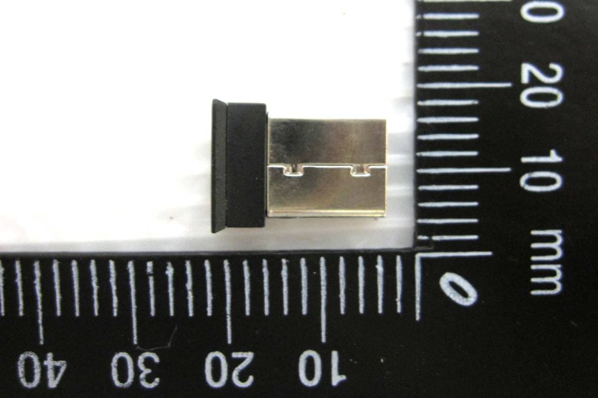
Click to zoom
Application Details
- Equipment Class
- DXX - Part 15 Low Power Communication Device Transmitter
- Date of Grant
- May 23, 2011
- Application Purpose
- Original Equipment
- Date of Application
- May 23, 2011
- Equipment Note
- GIGABYTE Nano receiver
- Frequency Range
- 2402.00000000 - 2479.00000000
- Country
- Taiwan
Documents & Files
Document Text
Text extracted from the exhibit documents filed with the FCC. Open a document above to read the original.
Users Manual
Wireless LASER MOUSE User's Guide This device complies with Part 15 of the FCC Rules. Operation is subject to the following two conditions: (1) This device may not cause harmful interference. and (2) This device must accept any interference received, including interference that may cause undesired operation. This symbol on the product or in the instructions means that your electrical and electronic equipment should be disposed at the end its life separately from your household waste. There are sparate collection system for recycling in the EU. For more information, please contact the local authority or your retailer where you purchased the product. ECO600 Long-lasting Wireless Laser Mouse Model nr: 28713ECO600 FCC ID: JCK28713ECO600 GIGABYTE Nano recevier Model nr: 28713C55RX FCC ID: JCK28713C55RX Wheel button ID reset button Mouse Introduction Congratulations on your purchase of the most innovative mini wireless mouse. With an incredible sensitivity to surface details and high tracking speed than other mice, the mouse can track reliably even on tricky polished or wood-grain surfaces. It offers even more advance that will make you more productive and more comfortable. A. Hardware Installation 2.4GHz (distance 6~8m), 16 Channels/2 16 ID Using state-of-art technology. High tracking speed and sensitivity. Nano receiver. Longer battery life. Auto-Link, Plug and Play! No need to set the channel ID. Power on/off switch. Ergonomic design. 800/1200/1600 dpi switchable. Rubber side grips. 2*AA Alkaline batteries included. Power on/off switch This product complies with IEC 60825-1, Class I laser product. The product complies with FCC and CE rules. Safety Notice Please DO NOT direct the laser beam at anyone's eyes. Features + - A wrong battery placement may cause batteries overheat. Battery compartment cover 2 * AA batteries Battery cover The unit offers a strong power saving management. Once the mouse accesses the sleeping mode, " to click any button of the mouse" is compulsory to wake it up. Power on/off: There is a Power on/off switch designed to save the batteries power while non-usage of a longer period. User can push DPI button to change the resolution. The LED on wheel bar will be flashed when dpi has been successfully switched. Receiver Internet Forward & Backward button 1. Insert the batteries a. Remove the battery compartment cover on the top case of the mouse. b. Fit in the batteries accordingly to the diagram indicated in the battery cabinet. c. Close the battery compartment cover properly. d. Make sure the Power on-off switch on the bottom of the mouse is ON. e. The Low Power LED on the wheel bar will be on for 6 seconds if the mouse power is on. Receiver Dpi ( + ) button Dpi ( - ) button Dpi light indicator 800 dpi1200 dpi1600 dpi ◎ Battery use reminders 1. Remove worn-out batteries from equipment immediately and dispose of promptly. 2. Keep all batteries (used or new) out of the reach of children. 3. To have the batteries with a regular check and replace new batteries if not used for a long time. 4. Never dispose of batteries in fire, as they could explode. 5. Always replace all the batteries at the same time. Mixing old and new batteries or mining types (such as alkaline with zinc carbon) will reduce overall performance and could cause leakage or rupture. 6. Do not mix different types of batteries (e.g. Ni MH, NiCd, alkaline, and etc) in the mouse. 7. Remove batteries from the electrical device if the device is not going to be used for a long time. 8. If the performance of the batteries decreases substantially, it is time to replace the batteries. ◎ Trouble Shooting a. Make sure you have connected the receiver correctly to the computer's USB port. b. For the best performance, we suggest you to locate the receiver with a distance from other electrical devices, such as the computer, the computer monitor or external storage drives. c. Make sure you have set the communication between the receiver and the mouse. Refer to the Communication :The mouse and the receiver d. If you find the communication channel does not connect well. You can use the software connection tool to re-connect the mouse & receiver to reset a new channel ID. You are able to get the software from the included diskette of the package or download from your local brand vendor's website. e. Some system devices might conflict with the mouse. Confirm the IRQ/address settings of these devices for conflicts, and change the settings as required. f. Make sure that you are not working the mouse on glossy or reflective surfaces. Press ID reset button Execute ID connection software 1 23 ID links OK! 4. Replace the new batteries Please replace a pair of new batteries and follow the previous instructions. (2, 3) The red LED on the scroll wheel is the low batteries power indicator. It indicates that batteries inside the mouse are needed to be replaced. Note While the mouse is working, if encountering any interference, the mouse and the receiver will automatically source out and transfer to another free channel. During the transferring, the cursor movement may have a second delay. Note 3. Communication : The mouse & the receiver The 2.4Ghz RF mouse features a dual-way transmission technology which enables the mouse and the receiver auto-communication. A. Auto-link mode 1. Make sure the Power On-Off Switch on the bottom of the mouse is ON. 2. Operate the mouse, and cursor's movement is mapping mouse movement. Now the mouse and the receiver is auto-linked successfully. B. Manual mode If you find the communication channel does not connect well, you can use the software connection tool to re-connect the mouse & receiver to reset a new channel ID. You are able to get the software from the included diskette of the package or download from your local brand vendor's website. FCC statement This equipment has been tested and found to comply with the limits for a class B digital device, pursuant to Part 15 of the FCC Rules. These limits are des…
Text truncated - open the document above for the full version.
External Photos
FCC ID: JCK28713C55RX International Standards Laboratory Report Number: ISL-11LR024FC APPENDIX 2 EXTERNAL PHOTOGRAPHS OF EUT FCC ID: JCK28713C55RX International Standards Laboratory Report Number: ISL-11LR024FC Front View of EUT Front View of EUT
Internal Photos
FCC ID: JCK28713C55RX International Standards Laboratory Report Number: ISL-11LR024FC APPENDIX 3 INTERNAL PHOTOGRAPHS OF EUT FCC ID: JCK28713C55RX International Standards Laboratory Report Number: ISL-11LR024FC Internal of EUT – 1 Internal of EUT – 2 ~ End of Report ~ RF Ant.
Test Report
Page: 1 of 33 TEST REPORT of FCC Part 15 Subpart C New Application; Class I PC; Class II PC Product : GIGABYTE Nano receiver Brand: GIGABYTE Model: 28713C55RX Model Difference: N/A FCC ID: JCK28713C55RX FCC Rule Part: §15.249 Applicant: GIGA-BYTE Technology Co., Ltd. Address: No. 6, Bau Chiang Road, Hsin-Tien, Taipei, Taiwan Test Performed by: International Standards Laboratory <Lung-Tan LAB> *Site Registration No. BSMI: SL2-IN-E-0013; MRA TW1036; TAF: 0997; IC: IC4067B-3; *Address: No. 120, Lane 180, San Ho Tsuen, Hsin Ho Rd. Lung-Tan Hsiang, Tao Yuan County 325, Taiwan *Tel : 886-3-407-1718; Fax: 886-3-407-1738 Report No.: ISL-11LR024FC Issue Date : 2011/05/09 Test results given in this report apply only to the specific sample(s) tested and are traceable to national or international standard through calibration of the equipment and evaluating measurement uncertainty herein. This report MUST not be used to claim product endorsement by TAF, NVLAP or any agency of the Government. This test report shall not be reproduced except in full, without the written approval of International Standards Laboratory. -2 of 27- FCC ID: JCK28713C55RX International Standards Laboratory Report Number: ISL-11LR024FC VERIFICATION OF COMPLIANCE Applicant: GIGA-BYTE Technology Co., Ltd. Product Description: GIGABYTE Nano receiver Brand Name: GIGABYTE FCC ID: JCK28713C55RX FCC Rule Part: §15.249 Model No.: 28713C55RX Model Difference: N/A Date of test: 2011/04/28 ~ 2011/05/06 Date of EUT Received: 2011/04/28 We hereby certify that: All the tests in this report have been performed and recorded in accordance with the standards described above and performed by an independent electromagnetic compatibility consultant, International Standards Laboratory. The test results contained in this report accurately represent the measurements of the characteristics and the energy generated by sample equipment under test at the time of the test. The sample equipment tested as described in this report is in compliance with the limits of above standards. Test By: Date: 2011/05/09 Dion Chang / Engineer Prepared By: Date: 2011/05/09 Eva Kao / Asst. Supervisor Approved By: Date: 2011/05/09 Jim Chu / Director -3 of 27- FCC ID: JCK28713C55RX International Standards Laboratory Report Number: ISL-11LR024FC Version Version No. Date Description 00 2011/05/09 Initial creation of document -4 of 27- FCC ID: JCK28713C55RX International Standards Laboratory Report Number: ISL-11LR024FC Table of Contents 1 GENERAL INFORMATION ................................................................................. 5 1.1 PRODUCT DESCRIPTION......................................................................................................... 5 1.2 RELATED SUBMITTAL(S) / GRANT (S) .................................................................................... 5 1.3 TEST METHODOLOGY............................................................................................................ 5 1.4 TEST FACILITY....................................................................................................................... 5 1.5 SPECIAL ACCESSORIES........................................................................................................... 5 1.6 EQUIPMENT MODIFICATIONS................................................................................................. 5 2 SYSTEM TEST CONFIGURATION .................................................................... 6 2.1 EUT CONFIGURATION............................................................................................................ 6 2.2 EUT EXERCISE....................................................................................................................... 6 2.3 TEST PROCEDURE................................................................................................................... 6 2.4 MEASUREMENT EQUIPMENT USED: ....................................................................................... 7 2.5 LIMITATION............................................................................................................................ 9 2.6 CONFIGURATION OF TESTED SYSTEM.................................................................................. 11 3 SUMMARY OF TEST RESULTS........................................................................ 12 4 DESCRIPTION OF TEST MODES..................................................................... 12 5 CONDUCTED EMISSIONS TEST...................................................................... 13 5.1 MEASUREMENT PROCEDURE: .............................................................................................. 13 5.2 TEST SET-UP (BLOCK DIAGRAM OF CONFIGURATION) ...................................................... 13 5.3 MEASUREMENT EQUIPMENT USED: ..................................................................................... 13 5.4 MEASUREMENT RESULT: ..................................................................................................... 13 6 RADIATED EMISSION TEST ............................................................................ 16 6.1 MEASUREMENT PROCEDURE............................................................................................... 16 6.2 TEST SET-UP (BLOCK DIAGRAM OF CONFIGURATION) ...................................................... 16 6.3 MEASUREMENT EQUIPMENT USED: ..................................................................................... 17 6.4 FIELD STRENGTH CALCULATION......................................................................................... 17 6.5 MEASUREMENT RESULT...................................................................................................... 18 7 20 DB BAND WIDTH MEASUREMENT ........................................................... 25 7.1 MEASUREMENT PROCEDURE............................................................................................... 25 7.2 TEST SET-UP (BLOC…
Text truncated - open the document above for the full version.
Test Setup Photos
FCC ID: JCK28713C55RX International Standards Laboratory Report Number: ISL-11LR024FC APPENDIX 1 PHOTOGRAPHS OF SETUP FCC ID: JCK28713C55RX International Standards Laboratory Report Number: ISL-11LR024FC Radiated Emission Setup Photos FCC ID: JCK28713C55RX International Standards Laboratory Report Number: ISL-11LR024FC Conducted Emission Setup Photos
Contact Information
Applicant
Alain Sam-Lai
Technical Contact
International Stantards LaboratoryVincent Su
No. 120, Lane 180, San Ho Tsuen,Hsin Ho · Taiwan
Test Firm
International Standards LaboratoryDavid Wu
Technical Specifications
| # | Rule Parts | Frequency Range | Power Output |
|---|---|---|---|
| 1 | 15C | 2.40 GHz - 2.48 GHz | - |
Other Applications from GIGA-BYTE TECHNOLOGY CO., LTD.

JCKGM-AORUSM6
Jun 26, 2023Mouse
Equipment Class
DTS - Digital Transmission System
JCKS3
Jun 26, 2023Mouse Dongle
Equipment Class
DTS - Digital Transmission System
JCK28713AIREM60
Jul 30, 2015Sapphire Blue Optical Mouse
Equipment Class
DXX - Part 15 Low Power Communication Device Transmitter
JCK287137580RX
Jul 30, 2015Wireless Receiver
Equipment Class
DXX - Part 15 Low Power Communication Device Transmitter
JCK-MSN09C01
Feb 10, 2015NFC Controller Module with Integrated Antenna
Equipment Class
DXX - Part 15 Low Power Communication Device Transmitter