JEBDR-024Receiver
Mascot Electric Co., Ltd.
Click to zoom
Application Details
- Equipment Class
- DTS - Digital Transmission System
- Date of Grant
- May 23, 2021
- Application Purpose
- Original Equipment
- Date of Application
- May 23, 2021
- Equipment Note
- Receiver
- Frequency Range
- 2407.00000000 - 2480.00000000
- Company
- Mascot Electric Co., Ltd.
- Country
- Taiwan
Documents & Files
Document Text
Text extracted from the exhibit documents filed with the FCC. Open a document above to read the original.
Users Manual
USER’S MANUAL 2.4GHz Digital WIRELESS MICROPHONE SYSTEM Contents: Introduction Quick Start Guide Product Description System Operation Color Label Identification Trouble Shooting Specification -------------------------------------------------------------------------- 1 ------------------------------------------------------------------ 2 ---------------------------------------------------------------- 4 ------------------------------------------------------------------ 7 --------------------------------------------------------- 12 ------------------------------------------------------------------- 13 ------------------------------------------------------------------------- 14 Thank you for purchasing our product. This wireless microphone system operates in 2.4GHz frequency with 8 selectable channels. Please read this instruction manual carefully before operating the system. This manual covers the function and operation of the wireless microphone system. Federal Communication Commission Interference Statement Introduction 1 This equipment has been tested and found to comply with the limits for a Class B digital device, pursuant to Part 15 of the FCC Rules. These limits are designed to provide reasonable protection against harmful interference in a residential installation. This equipment generates, uses and can radiate radio frequency energy and, if not installed and used in accordance with the instructions, may cause harmful interference to radio communications. However, there is no guarantee that interference will not occur in a particular installation. If this equipment does cause harmful interference to radio or television reception, which can be determined by turning the equipment off and on, the user is encouraged to try to correct the interference by one of the following measures: . Reorient or relocate the receiving antenna. . Increase the separation between the equipment and receiver. . Connect the equipment into an outlet on a circuit different from that to which the receiver is connected. . Consult the dealer or an experienced radio/TV technician for help. FCC Caution: To assure continued compliance, any changes or modifications not expressly approved by the party responsible for compliance could void the user's authority to operate this equipment. (Example - use only shielded interface cables when connecting to computer or peripheral devices). FCC Radiation Exposure Statement This equipment complies with FCC RF radiation exposure limits set forth for an uncontrolled environment. This equipment should be installed and operated with a minimum distance of 0.5 centimeters between the radiator and your body. This transmitter must not be co-located or operating in conjunction with any other antenna or transmitter. The antennas used for this transmitter must be installed to provide a separation distance of at least 0.5 cm from all persons and must not be co-located or operating in conjunction with any other antenna or transmitter. This device complies with Part 15 of the FCC Rules. Operation is subject to the following two conditions: (1) This device may not cause harmful interference, and (2) This device must accept any interference received, including interference that may cause undesired operation. AUDIO OUT DC 12V 500mA UNBALANCED LINEMIC SQ BALANCED ANT B ANT A RoHS AUDIO OUT DC 12V 500mA UNBALANCED LINEMIC SQ BALANCED ANT B ANT A RoHS AC/DC ADAPTER Quick Start Guide 2 1. Connected Receiver Power Cable 2. Connect Mixer or Amplifier 3. Select Channel 6 7 8 9 10 11 12 1 2 3 4 5 3 6 7 8 9 10 11 12 1 2 3 4 5 1 6 7 8 9 10 11 12 1 2 3 4 5 3 4. Insert Batteries 5. SYNC 3 Quick Start Guide 1.5V AA 1.5V AA 6 7 8 9 10 11 12 1 2 3 4 5 1.5V AA 1.5V AA Power Pair -20 10 0 6 7 8 9 10 11 12 1 2 3 4 5 TALK 1.5V AA 1.5V AA Power Sync -20 10 0 1.5V AA 1.5V AA Power Pair -20 10 0 < 1M Step 2 OR Step 1 Pair TALK Press 2 Times Press 2 Times Front : Rear : 4 Receiver 1. Balanced XLR Audio Output 2. Unbalanced 6.3mm Audio Output 3. MIC/LINE Switch: Use this switch to adjust audio output level for MIC level (-20dB) or LINE level (0dB). 4. Power Adapter Connector 1. Power Button 2. Pair Button: Press the button to activate pair function with transmitter. 3. RF Indicator: The LED lights to indicate that RF signal has been received. 4. LED Display: Display selected channel. 5. AF Indicator: The LED lights to indicate that AF signal has been received. 6. Battery LED: If the Red LED stays flashing, it indicate the batteries on transmitter will out of power soon, and should be changed. 7. Channel Selector: Tap the channel backward. 8. Volume Control: Adjust the receiver output level. 9. Fixed 2.4GHz Antenna 1324 AUDIO OUT DC 12V 500mA UNBALANCED LINEMIC SQ BALANCED 1234599678 5 Handheld Microphone TALK 1.5V AA 1.5V AA 1 6 2 3 LED Indicator Status GreenReady Flashing Green The synchronization process is actuated. Flashing Red Low battery power when less than 10 minutes operation 1. Grille: Protects the microphone capsule and helps reduce breath sounds and wind noise. 2. Pair Button: Press the button to activate pair function with receiver. 3. Talk Button: Push the button up to talk. Push the button down for mute. 4. Battery compartment: Insert two AA size batteries into the compartment and make sure that the polarity of batteries is correct. 5. Power Button: Press for 1 second to power microphone on or press for 3 seconds to power microphone off. 6. Power LED: Indicate the power / low battery level status. 4 5 6 Bodypack Transmitter 1.5V AA 1.5V AA Power Pair -20 -10 0 2 4 3 1 8 6 7 5 1. Power Button: Press for 1 second to power transmitter on or press for 3 seconds to power transmitter off. 2. Mute Button: With the transmitter on, a slight press for button will toggle between mute and unmute function. 3. Power LED: Indicate the power / low battery level status. 4. MUTE LED: Blue LED light on in mute status. 5. Pair Button: Press the button to activate pair function with receiver. 6. Battery compartment: Insert…
Text truncated - open the document above for the full version.
External Photos
Registration number: W6M22102-20693-FCC FCC ID: JEBDR-024 External Photos Worldwide Testing Services(Taiwan) Co., Ltd. Appendix page 2 of 20 Registration number: W6M22102-20693-FCC FCC ID: JEBDR-024 Worldwide Testing Services(Taiwan) Co., Ltd. Appendix page 3 of 20 Registration number: W6M22102-20693-FCC FCC ID: JEBDR-024 Worldwide Testing Services(Taiwan) Co., Ltd. Appendix page 4 of 20 Registration number: W6M22102-20693-FCC FCC ID: JEBDR-024 Worldwide Testing Services(Taiwan) Co., Ltd. Appendix page 5 of 20 Registration number: W6M22102-20693-FCC FCC ID: JEBDR-024 Worldwide Testing Services(Taiwan) Co., Ltd. Appendix page 6 of 20 Registration number: W6M22102-20693-FCC FCC ID: JEBDR-024 Worldwide Testing Services(Taiwan) Co., Ltd. Appendix page 7 of 20 Registration number: W6M22102-20693-FCC FCC ID: JEBDR-024 Worldwide Testing Services(Taiwan) Co., Ltd. Appendix page 8 of 20 Registration number: W6M22102-20693-FCC FCC ID: JEBDR-024 Worldwide Testing Services(Taiwan) Co., Ltd. Appendix page 9 of 20
Internal Photos
Registration number: W6M22102-20693-FCC FCC ID: JEBDR-024 Internal Photos Worldwide Testing Services(Taiwan) Co., Ltd. Appendix page 10 of 20 Registration number: W6M22102-20693-FCC FCC ID: JEBDR-024 Worldwide Testing Services(Taiwan) Co., Ltd. Appendix page 11 of 20 Registration number: W6M22102-20693-FCC FCC ID: JEBDR-024 Worldwide Testing Services(Taiwan) Co., Ltd. Appendix page 12 of 20 Registration number: W6M22102-20693-FCC FCC ID: JEBDR-024 Worldwide Testing Services(Taiwan) Co., Ltd. Appendix page 13 of 20 Registration number: W6M22102-20693-FCC FCC ID: JEBDR-024 Worldwide Testing Services(Taiwan) Co., Ltd. Appendix page 14 of 20 Registration number: W6M22102-20693-FCC FCC ID: JEBDR-024 Worldwide Testing Services(Taiwan) Co., Ltd. Appendix page 15 of 20
RF Exposure Info
Registration number: W6M22102-20693-C-1 FCC ID: JEBDR-024 3.2 Equivalent Isotropic Radiated Power (EIRP) FCC Rule: 15.247(b)(3) EIRP = max. conducted output power + antenna gain EIRP = -22.23 dBm + 2.28 dBi [antenna gain claimed by manufacturer] = -19.95 dBm = 0.0101 mW 3.3 Exemption Limits for Routine Evaluation according to FCC KDB Publication RESULT: Test standard : FCC KDB Publication 447498 D01 General RF Exposure Guidance v06 According to 447498 D01 General RF Exposure Guidance v06: SAR evaluation, by measurement or numerical simulation, is not required when the corresponding SAR Exclusion Threshold condition, listed below, is satisfied. 3.3.1 Exemption Limits for Routine Evaluation – SAR Evaluation SAR evaluation is required if the separation distance between the user and/or bystander and the antenna and/or radiating element of the device is less than or equal to 20 cm, except when the device operates at or below the applicable output power level (adjusted for tune-up tolerance) for the specified separation distance defined in Table . Table: SAR evaluation — Exemption limits for routine evaluation based on frequency and separation distance MHz 5 10 15 20 25 mm 2480 9.95 18.92 28.87 37.84 47.79 SAR Test Exclusion Threshold (mW) MHz 30 35 40 45 50 mm 2480 56.74 66.69 76.63 85.61 95.56 SAR Test Exclusion Threshold (mW) Output power level shall be the higher of the maximum conducted or equivalent isotropically radiated power (e.i.r.p.) source-based, time-averaged output power. Established separation distance is 5 mm. Operating frequency band : 2407-2480 MHz Max. output power level at 5 mm separation distance at 2480 MHz according to table is: 9.95 mW The product is exempt from SAR Evaluation/Testing because the output power of 0.0101 mW is below the exemption limit of 9.95 mW. Worldwide Testing Services(Taiwan) Co., Ltd. Page 16 of 32
Test Report
of Applicant: MASCOT ELECTRIC CO., LTD Address: No.85, Changxing 1st St., Rende Dist., Tainan City 71741, Taiwan (R.O.C.) Tested and Prepared by Worldwide Testing Services (Taiwan) Co., Ltd. FCC Registration No.: TW1477, TW0020, TW1072 Industry Canada filed test laboratory Reg. No. 20037 Report No.: W6M22102-20693-C-1 6F, NO. 58, LANE 188, RUEY-KUANG RD., NEIHU TAIPEI 114, TAIWAN, R.O.C. TEL: 886-2-66068877 FAX: 886-2-66068879 E- mail: [email protected] 47 CFR PART 15 SUBPART C TEST REPORT for Receiver Model No.: DR-024 FCC ID: JEBDR-024 Registration number: W6M22102-20693-C-1 FCC ID: JEBDR-024 TABLE OF CONTENTS 1 GENERAL INFORMATION .............................................................................................................................. 2 1.1 NOTES ...................................................................................................................................................................... 2 1.2 TESTING LABORATORY ............................................................................................................................................. 3 1.2.1 Location .............................................................................................................................................................. 3 1.2.2 Details of accreditation status ............................................................................................................................ 3 1.3 DETAILS OF APPROVAL HOLDER ............................................................................................................................... 3 1.4 APPLICATION DETAILS .............................................................................................................................................. 4 1.5 GENERAL INFORMATION OF TEST ITEM ..................................................................................................................... 4 1.6 TEST STANDARDS ..................................................................................................................................................... 5 2 TECHNICAL TEST ............................................................................................................................................. 6 2.1 SUMMARY OF TEST RESULTS ..................................................................................................................................... 6 2.2 TEST ENVIRONMENT ................................................................................................................................................. 6 2.3 TEST EQUIPMENT LIST .............................................................................................................................................. 7 2.4 GENERAL TEST PROCEDURE ................................................................................................................................... 10 3 TEST RESULTS (ENCLOSURE) ..................................................................................................................... 12 3.1 PEAK OUTPUT POWER (TRANSMITTER) ................................................................................................................... 13 3.2 EQUIVALENT ISOTROPIC RADIATED POWER (EIRP) ............................................................................................... 16 3.3 EXEMPTION LIMITS FOR ROUTINE EVALUATION ACCORDING TO FCC KDB PUBLICATION .................................... 16 3.4 TRANSMITTER RADIATED EMISSIONS IN RESTRICTED BANDS ................................................................................ 17 3.5 SPURIOUS EMISSIONS (TX) ...................................................................................................................................... 18 3.6 RADIATED EMISSION ON THE BAND EDGE ............................................................................................................... 20 3.7 MINIMUM 6 DB BANDWIDTH .................................................................................................................................. 22 3.8 PEAK POWER SPECTRAL DENSITY .......................................................................................................................... 25 3.9 RADIATED EMISSION FROM RECEIVER PART .......................................................................................................... 28 3.10 POWER LINE CONDUCTED EMISSION ...................................................................................................................... 29 APPENDIX...........................................................................................................32 Worldwide Testing Services(Taiwan) Co., Ltd. Page 1 of 32 Registration number: W6M22102-20693-C-1 FCC ID: JEBDR-024 1 General Information 1.1 Notes The purpose of conformity testing is to increase the probability of adherence to the essential requirements or conformity specifications, as appropriate. The complexity of the technical specifications, however, means that full and thorough testing is impractical for both technical and economic reasons. Furthermore, there is no guarantee that a test sample which has passed all the relevant tests conforms to a specification. Neither is there any guarantee that such a test sample will interwork with other genuinely open systems. The existence of the tests nevertheless provides the confidence that the test sample possesses the qualities as maintained and that is performance generally conforms to representative cases of communications equipment. The test results of this test report relate exclusively to the item tested as specified in 1.5. The test report may only be reproduced or published in full. Reproduction or publication of extracts from the report requires the prior written approval of the Worldwide Testing Services(Taiwan) Co., Ltd. Specific Conditions: Usage of the hereunder tested device in combination with other integra…
Text truncated - open the document above for the full version.
Test Setup Photos
Registration number: W6M22102-20693-FCC FCC ID: JEBDR-024 Set Up Photo of Radiated Emission EMI Below 1GHz Worldwide Testing Services(Taiwan) Co., Ltd. Appendix page 16 of 20 Registration number: W6M22102-20693-FCC FCC ID: JEBDR-024 Above 1GHz Worldwide Testing Services(Taiwan) Co., Ltd. Appendix page 17 of 20 Registration number: W6M22102-20693-FCC FCC ID: JEBDR-024 RF Below 1GHz Worldwide Testing Services(Taiwan) Co., Ltd. Appendix page 18 of 20 Registration number: W6M22102-20693-FCC FCC ID: JEBDR-024 Above 1GHz Worldwide Testing Services(Taiwan) Co., Ltd. Appendix page 19 of 20 Registration number: W6M22102-20693-FCC FCC ID: JEBDR-024 Set Up Photo of Conducted Emission Worldwide Testing Services(Taiwan) Co., Ltd. Appendix page 20 of 20
Contact Information
Applicant
Chia-Yu Chiang(President)
Technical Contact
Worldwide Testing Services (Taiwan) Co., Ltd.Danny Sung
[email protected]+886266068877
6F., No.58, Lane 188, Ruiguang Rd., Neihu District · Taipei · Taiwan
Test Firm
Worldwide Testing Services (Taiwan) Co., Ltd.Rex Kao
Technical Specifications
| # | Rule Parts | Frequency Range | Power Output |
|---|---|---|---|
| 1 | 15C | 2.41 GHz - 2.48 GHz | 60.00 µW |
Other Applications from Mascot Electric Co., Ltd.

JEBUF-9R1
Jul 04, 2023Handheld Microphone
Equipment Class
DWM - Part 15 Wireless Microphone
JEBDF-024
May 15, 2021Handheld Microphone
Equipment Class
DTS - Digital Transmission System
JEBDB-024
May 15, 2021Bodypack Transmitter
Equipment Class
DTS - Digital Transmission System
JEBUT-51B
Mar 30, 2020Bodypack Transmitter
Equipment Class
DWM - Part 15 Wireless Microphone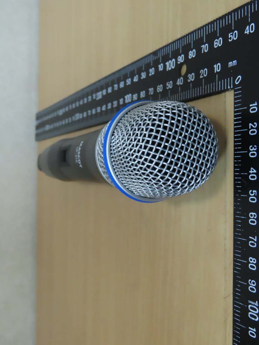
JEBUF-31B
Mar 30, 2020Handheld Microphone
Equipment Class
DWM - Part 15 Wireless Microphone