JEBUF-31BHandheld Microphone
Mascot Electric Co., Ltd.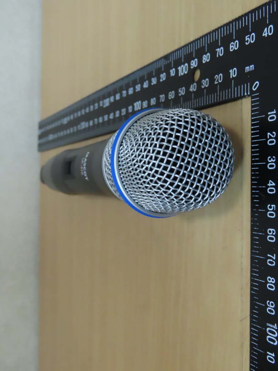
Click to zoom
Application Details
- Equipment Class
- DWM - Part 15 Wireless Microphone
- Date of Grant
- Mar 30, 2020
- Application Purpose
- Original Equipment
- Date of Application
- Mar 29, 2020
- Equipment Note
- Handheld Microphone
- Frequency Range
- 657.12500000 - 662.87500000
- Company
- Mascot Electric Co., Ltd.
- Country
- Taiwan
Documents & Files
Document Text
Text extracted from the exhibit documents filed with the FCC. Open a document above to read the original.
Users Manual
RS-51B / RS-55B RS-31B / RS-33B USER’S MANUAL WIRELESS MICROPHONE SYSTEM Channel Contents: Introduction Quick Start Guide Product Description System Operation Color Label Identification Trouble Shooting Specification -------------------------------------------------------------------------- 1 ------------------------------------------------------------------ 2 ---------------------------------------------------------------- 4 ------------------------------------------------------------------ 10 --------------------------------------------------------- 13 ------------------------------------------------------------------- 14 ------------------------------------------------------------------------- 15 This device complies with part 15 of the FCC rules. Operation is subject to the following two conditions:(1)This device may not cause harmful interferenceand (2) This device must accept any The changes or modifications not expressly approved by the party responsible for compliance could void the user’s authority to operate the equipment. IMPORTANT NOTE: To comply with the FCC RF exposure compliance requirements, no change to the antenna or the device is permitted. could result in the device exceeding the to operate the device. Thank you for purchasing our product. This PLL synthesized wireless microphone system operates in UHF band frequency with 8 selectable channels. Please read this instruction manual carefully before operating the system. This manual covers the function and operation of the wireless microphone system. Safety Do not spill liquid on the appliance and do not drop it on a hard concrete floor. Do not place the equipment near heat sources such as radiators, heating ducts, amplifier, etc. Do not expose the equipment to direct sunlight, extremely dust, excessive moisture, rain, mechanical vibrations, or shock. Take out the battery from transmitter, if the appliance has been not used for a longer period. This will avoid the damage resulting from a defective leaking battery. WARNING: To reduce the risk of fire or electric shock, do not use the products near water and do not expose them to rain or moisture. Environment When disposing the equipment, remove the batteries, separate the case, circuit boards, and cables, and dispose of all components in accordance with local waste disposal rules. Do not throw used batteries into a fire or garbage bin with domestic rubbish. Be sure to dispose of used batteries in accordance with local waste disposal rules. If the equipment is not going to be used for a long time, disconnect the AC adapter from the power outlet. Please note that if you turn the equipment off while leaving the AC adapter plugged in, it is not fully isolated from the power supply. No guarantee claims for the equipment and no liability for any resulting personal damage or material damage will be accepted if the equipment is used for other purpose than originally intended, if the equipment is not correctly connected or operated, or if the equipment is not repaired in an expert way. Notice : FCC Statement interference received, including interference that may cause undesired operation. Introduction Any change to the antenna or the device RF exposure requirements and void user’s authority 1 1. Connected Receiver Power Cable 2. Connect Mixer or Amplifier 2 Quick Start Guide 3. Insert Batteries 4. Select channel 3 Quick Start Guide Front : Rear : RS-51B: Diversity Receiver 4 Receiver 1. Balanced XLR Audio Output 2. Unbalanced 6.35mm Audio Output 3. MIC/LINE Switch: Use this switch to adjust audio output level for MIC level (-20dB) or LINE level (0dB). 4. Squelch: Turn the knob to adjust the noise floor level. 5. DC Input Jack 1. Power Button: Press and hold for 2 sec. to turn the power on. Press and hold for 2 sec. to turn the power off. 2. AF Indicator: The indicator glows to indicate that audio signal has been received. 3. RF Indicator: The indicator glows to indicate that RF signal has been received. 4. LED Display: The 7 segment LED display shows the selected preset channel. 5. Channel Selector: Press and hold for 1 sec. to select the operating channels. 6. Antenna: Fixed UHF antenna. 7. Volume Control: Adjust the receiver output level. DC 12V 500mA MIC SQ 12 3 45667 13245 5 Front : Rear : RS-55B: Diversity Receiver Receiver 1. Balanced XLR Audio Output 2. Unbalanced 6.35mm Audio Output 3. MIC/LINE Switch: Use this switch to adjust audio output level for MIC level (-20dB) or LINE level (0dB). 4. Squelch: Turn the knob to adjust the noise floor level. 5. DC Input Jack 6. Mix Out: The audio output for CH A and CH B is mixed. 1. Power Button: Press and hold for 2 sec. to turn the power on. Press and hold for 2 sec. to turn the power off. 2. AF Indicator: The indicator glows to indicate that audio signal has been received. 3. RF Indicator: The indicator glows to indicate that RF signal has been received. 4. LED Display: The 7 segment LED display shows the selected preset channel. 5. Channel Selector: Press and hold for 1 sec. to select the operating channels. 6. Antenna: Fixed UHF antenna. 7. Volume Control: Adjust the receiver output level. DC 12V 500mA MIC SQ 124572457 3322445 Front : Rear : RS-31B: Diversity Receiver 6 Receiver 1. Balanced XLR Audio Output 2. Unbalanced 6.35mm Audio Output 3. MIC/LINE Switch: Use this switch to adjust audio output level for MIC level (-20dB) or LINE level (0dB). 4. Squelch: Turn the knob to adjust the noise floor level. 5. DC Input Jack 1. Power Button: Press and hold for 2 sec. to turn the power on. Press and hold for 2 sec. to turn the power off. 2. AF Indicator: The indicator glows to indicate that audio signal has been received. 3. RF Indicator: The indicator glows to indicate that RF signal has been received. 4. LED Display: The 7 segment LED display shows the selected preset channel. 5. Channel Selector: Press and hold for 0.5 sec. to select the operating channels. 6. Antenna: Fixed UHF antenna. DC 12V 500mA MIC SQ 3245 124566 Front : Rea…
Text truncated - open the document above for the full version.
Cover Letter(s)
空中線特性 Center freq.(MHz): 809 Polarization : XY Max gain(dBi): 1.60 Min gain(dBi): -18.03 Avg gain(dBi):-3.60 Model Number:UF-31B
External Photos
Registration number: W6M21912-19528-C-1 FCC ID: JEBUF-31B External Photos Worldwide Testing Services(Taiwan) Co., Ltd. Appendix Page 1 of 21 Registration number: W6M21912-19528-C-1 FCC ID: JEBUF-31B Worldwide Testing Services(Taiwan) Co., Ltd. Appendix page 2 of 21 Registration number: W6M21912-19528-C-1 FCC ID: JEBUF-31B Worldwide Testing Services(Taiwan) Co., Ltd. Appendix page 3 of 21 Registration number: W6M21912-19528-C-1 FCC ID: JEBUF-31B Worldwide Testing Services(Taiwan) Co., Ltd. Appendix page 4 of 21 Registration number: W6M21912-19528-C-1 FCC ID: JEBUF-31B Worldwide Testing Services(Taiwan) Co., Ltd. Appendix page 5 of 21 Registration number: W6M21912-19528-C-1 FCC ID: JEBUF-31B Worldwide Testing Services(Taiwan) Co., Ltd. Appendix page 6 of 21 Registration number: W6M21912-19528-C-1 FCC ID: JEBUF-31B Internal Photos Worldwide Testing Services(Taiwan) Co., Ltd. Appendix page 7 of 21
Internal Photos
Registration number: W6M21912-19528-C-1 FCC ID: JEBUF-31B Worldwide Testing Services(Taiwan) Co., Ltd. Appendix page 8 of 21 Registration number: W6M21912-19528-C-1 FCC ID: JEBUF-31B Worldwide Testing Services(Taiwan) Co., Ltd. Appendix page 9 of 21 Registration number: W6M21912-19528-C-1 FCC ID: JEBUF-31B Worldwide Testing Services(Taiwan) Co., Ltd. Appendix page 10 of 21 Registration number: W6M21912-19528-C-1 FCC ID: JEBUF-31B Worldwide Testing Services(Taiwan) Co., Ltd. Appendix page 11 of 21 Registration number: W6M21912-19528-C-1 FCC ID: JEBUF-31B Worldwide Testing Services(Taiwan) Co., Ltd. Appendix page 12 of 21 Registration number: W6M21912-19528-C-1 FCC ID: JEBUF-31B Worldwide Testing Services(Taiwan) Co., Ltd. Appendix page 13 of 21 Registration number: W6M21912-19528-C-1 FCC ID: JEBUF-31B Worldwide Testing Services(Taiwan) Co., Ltd. Appendix page 14 of 21 Registration number: W6M21912-19528-C-1 FCC ID: JEBUF-31B Worldwide Testing Services(Taiwan) Co., Ltd. Appendix page 15 of 21 PCB Antenna / Gain: 1.6 dBi Registration number: W6M21912-19528-C-1 FCC ID: JEBUF-31B Worldwide Testing Services(Taiwan) Co., Ltd. Appendix page 16 of 21 Registration number: W6M21912-19528-C-1 FCC ID: JEBUF-31B Worldwide Testing Services(Taiwan) Co., Ltd. Appendix page 17 of 21 Registration number: W6M21912-19528-C-1 FCC ID: JEBUF-31B Worldwide Testing Services(Taiwan) Co., Ltd. Appendix page 18 of 21 Registration number: W6M21912-19528-C-1 FCC ID: JEBUF-31B Worldwide Testing Services(Taiwan) Co., Ltd. Appendix page 19 of 21
RF Exposure Info
Equivalent Isotropic Radiated Power (EIRP) FCC Rule: 15.247(b)(3) 510.125-607.875 MHz EIRP = max. conducted output power + antenna gain EIRP = 10.54 dBm = 11.32 mW 614.125-615.875 MHz EIRP = max. conducted output power + antenna gain EIRP = 9.19 dBm = 8.30 mW 657.125-662.875 MHz EIRP = max. conducted output power + antenna gain EIRP = 9.68 dBm = 9.29 mW Exemption Limits for Routine Evaluation according to FCC KDB Publication RESULT: Test standard : FCC KDB Publication 447498 D01 General RF Exposure Guidance v06 According to 447498 D01 General RF Exposure Guidance v06: SAR evaluation, by measurement or numerical simulation, is not required when the corresponding SAR Exclusion Threshold condition, listed below, is satisfied. 3.3.1 Exemption Limits for Routine Evaluation – SAR Evaluation SAR evaluation is required if the separation distance between the user and/or bystander and the antenna and/or radiating element of the device is less than or equal to 20 cm, except when the device operates at or below the applicable output power level (adjusted for tune-up tolerance) for the specified separation distance defined in Table . Table: SAR evaluation — Exemption limits for routine evaluation based on frequency and separation distance 510.125-607.875 MHz MHz 5 10 15 20 25 mm 559 20.30 41.60 61.90 82.49 103.51 SAR Test Exclusion Threshold (mW) MHz 30 35 40 45 50 mm 559 123.81 145.11 165.41 185.99 207.01 SAR Test Exclusion Threshold (mW) Output power level shall be the higher of the maximum conducted or equivalent isotropically radiated power (e.i.r.p.) source-based, time-averaged output power. Established separation distance is 5 mm. Operating frequency band : 510.125-607.875 MHz Max. output power level at 5 mm separation distance at 559 MHz according to table is: 20.30 mW The product is exempt from SAR Evaluation/Testing because the output power of 11.32 mW is below the exemption limit of 20.30 mW. 614.125-615.875 MHz MHz 5 10 15 20 25 mm 614.125 19.44 39.88 59.33 79.20 99.21 SAR Test Exclusion Threshold (mW) MHz 30 35 40 45 50 mm 614.125 118.65 139.10 158.54 178.41 198.42 SAR Test Exclusion Threshold (mW) Output power level shall be the higher of the maximum conducted or equivalent isotropically radiated power (e.i.r.p.) source-based, time-averaged output power. Established separation distance is 5 mm. Operating frequency band : 614.125-615.875 MHz Max. output power level at 5 mm separation distance at 614.125 MHz according to table is: 19.44 mW The product is exempt from SAR Evaluation/Testing because the output power of 8.30 mW is below the exemption limit of 19.44 mW. 657.125-662.875 MHz MHz 5 10 15 20 25 mm 657.125 18.77 38.54 57.32 76.63 95.86 SAR Test Exclusion Threshold (mW) MHz 30 35 40 45 50 mm 657.125 114.63 134.40 153.18 172.49 191.72 SAR Test Exclusion Threshold (mW) Output power level shall be the higher of the maximum conducted or equivalent isotropically radiated power (e.i.r.p.) source-based, time-averaged output power. Established separation distance is 5 mm. Operating frequency band : 657.125-662.875 MHz Max. output power level at 5 mm separation distance at 657.125 MHz according to table is:18.77 mW The product is exempt from SAR Evaluation/Testing because the output power of 9.29 mW is below the exemption limit of 18.77 mW.
Test Report
of Applicant: MASCOT ELECTRIC CO., LTD Address: No.85, Changxing 1st St., Rende Dist., Tainan City 71741, Taiwan (R.O.C.) Tested and Prepared by Worldwide Testing Services (Taiwan) Co., Ltd. FCC Registration No.: TW1477, TW0020, TW1072 Industry Canada filed test laboratory Reg. No. 20037 A2LA Accredited No.: 2732.01 Report No.: W6M21912-19528-C-1 6F, NO. 58, LANE 188, RUEY-KUANG RD., NEIHU TAIPEI 114, TAIWAN, R.O.C. TEL: 886-2-66068877 FAX: 886-2-66068879 E-mail: [email protected] FCC PART 15 SUBPART C TEST REPORT for Handheld Microphone Model No.: UF-31B FCC ID: JEBUF-31B Registration number: W6M21912-19528-C-1 FCC ID: JEBUF-31B TABLE OF CONTENTS CERTIFICATION OF TEST REPORT ................................................................................................ 2 1 GENERAL INFORMATION .......................................................................................................... 2 1.1 N OTES .......................................................................................................................................... 2 1.2 T ESTING LABORATORY ................................................................................................................ 3 1.2.1 Location .................................................................................................................................. 3 1.2.2 Details of accreditation status ................................................................................................. 3 1.3 DETAILS OF APPROVAL HOLDER ................................................................................................... 3 1.4 A PPLICATION DETAILS ................................................................................................................. 4 1.5 GENERAL INFORMATION OF TEST ITEM ........................................................................................ 4 1.6 TEST STANDARDS ......................................................................................................................... 4 2 TECHNICAL TEST ......................................................................................................................... 5 2.1 SUMMARY OF TEST RESULTS ........................................................................................................ 5 2.2 T EST ENVIRONMENT .................................................................................................................... 5 2.3 TEST EQUIPMENT LIST ................................................................................................................. 6 2.4 GENERAL TEST PROCEDURE ........................................................................................................ 9 3 TEST RESULTS (ENCLOSURE) ................................................................................................ 10 4 RF POWER OUTPUT, FCC15.236 (D) ........................................................................................ 11 4.1 T EST PROCEDURE ....................................................................................................................... 11 4.2 TEST RESULTS ........................................................................................................................... 12 5 OCCUPIED BANDWIDTH, FCC15.236 (F) / /EMISSION MASK, FCC15.236 (G) ............. 26 5.1 TEST PROCEDURE ...................................................................................................................... 26 5.2 TEST RESULTS ............................................................................................................................ 26 6 RADIATED SPURIOUS EMISSION , FCC 15.236(G) .......................................................... 35 6.1 T EST PROCEDURE ....................................................................................................................... 35 6.2 T EST RESULTS ............................................................................................................................ 35 7 FREQUENCY STABILITY, FCC 15.236(F)(3) .......................................................................... 36 7.1 TEST PROCEDURE ....................................................................................................................... 36 7.2 TEST RESULTS ............................................................................................................................ 36 8 LINE CONDUCTED EMISSION , FCC 15.207 .......................................................................... 39 8.1 TEST PROCEDURE ....................................................................................................................... 39 8.2 TEST RESULTS ........................................................................................................................... 39 Worldwide Testing Services(Taiwan) Co., Ltd. Page 1 of 40 Registration number: W6M21912-19528-C-1 FCC ID: JEBUF-31B 1 General Information 1.1 Notes The purpose of conformity testing is to increase the probability of adherence to the essential requirements or conformity specifications, as appropriate. The complexity of the technical specifications, however, means that full and thorough testing is impractical for both technical and economic reasons. Furthermore, there is no guarantee that a test sample which has passed all the relevant tests conforms to a specification. Neither is there any guarantee that such a test sample will interwork with other genuinely open systems. The existence of the tests nevertheless provides the confidence that the test sample possesses the qualities as maintained and that is performance generally conforms to representative cases of communications equipment. The test results of this test report relate exclusively to the item tested as specified in 1.5. The test report may only be reproduced or published in full. Reproduction or publication of extracts from the report requires the prior written approval of the World…
Text truncated - open the document above for the full version.
Test Setup Photos
Registration number: W6M21912-19528-C-1 FCC ID: JEBUF-31B Set Up Photo of Radiated Emission Below 1GHz Worldwide Testing Services(Taiwan) Co., Ltd. Appendix page 20 of 21 Registration number: W6M21912-19528-C-1 FCC ID: JEBUF-31B Above 1GHz Worldwide Testing Services(Taiwan) Co., Ltd. Appendix page 21 of 21
Contact Information
Applicant
Chia-Yu Chiang(President)
Technical Contact
Worldwide Testing Services (Taiwan) Co., Ltd.Danny Sung
[email protected]886-2-6606-8877
6F., No.58, Lane 188, Ruiguang Rd., Neihu · Taiwan
Non-Technical Contact
Worldwide Testing Services (Taiwan) Co., Ltd.Annabel Ou
[email protected]886-2-6606-8877
Test Firm
Worldwide Testing Services (Taiwan) Co., Ltd.Rex Kao
Technical Specifications
| # | Rule Parts | Frequency Range | Power Output |
|---|---|---|---|
| 3 | 15C | 657.125 MHz - 662.875 MHz | 9.30 mW |
Other Applications from Mascot Electric Co., Ltd.

JEBUF-9R1
Jul 04, 2023Handheld Microphone
Equipment Class
DWM - Part 15 Wireless Microphone
JEBDR-024
May 23, 2021Receiver
Equipment Class
DTS - Digital Transmission System
JEBDF-024
May 15, 2021Handheld Microphone
Equipment Class
DTS - Digital Transmission System
JEBDB-024
May 15, 2021Bodypack Transmitter
Equipment Class
DTS - Digital Transmission System
JEBUT-51B
Mar 30, 2020Bodypack Transmitter
Equipment Class
DWM - Part 15 Wireless Microphone