JEBQF-20Wireless Microphone
Mascot Electric Co., Ltd.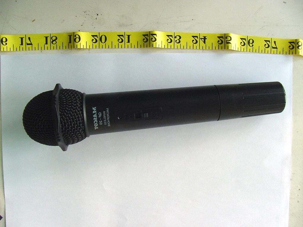
Click to zoom
Application Details
- Equipment Class
- TNF - Licensed Non-Broadcast Transmitter Held to Face
- Date of Grant
- Aug 05, 2002
- Application Purpose
- Original Equipment
- Date of Application
- Aug 05, 2002
- Equipment Note
- Wireless Microphone
- Frequency Range
- 174.00000000 - 216.00000000
- Company
- Mascot Electric Co., Ltd.
- Country
- Taiwan
Documents & Files
Document Text
Text extracted from the exhibit documents filed with the FCC. Open a document above to read the original.
Cover Letter(s)
From: willyauo [[email protected]] Sent: Tuesday, August 06, 2002 5:47 AM To: Mike Kuo Subject: Re: WA GOL INDUSTRIAL CO., LTD., FCC ID:JEBQF-20, AN02T2113 Hi Mike, Thank you for your reviewing our application project. I am very sorry, because our assistant engineer gave me the test report form file records. I check the data can meet the limit in that test report. After I saw your attachment and checked the original draft writing data. I found the submitted test report to CCS in page 15 and 16 is wrong. Our assistant engineer has corrected this error after submitted application. So, when I checked the test report data can meet the limit. Please see the attachment is correct test data in page 15 & 16. Please check. Thank you very much. Best regards, Will Yauo / ETC ----- Original Message ----- From: Mike Kuo <[email protected]> To: 'etcemi-seed' <[email protected]> Cc: Will Yauo-Personal (E-mail) <[email protected]> Sent: Tuesday, August 06, 2002 6:11 AM Subject: RE: WA GOL INDUSTRIAL CO., LTD., FCC ID:JEBQF-20, AN02T2113 > Hi Will: > > Please take a look attached Page 16 of test report, your reply to Question > #6 indicated all spurious emissions are under -13dBm. Please take a look > again. > > Best Regards > > Mike Kuo > > > > -----Original Message----- > From: etcemi-seed [mailto:[email protected]] > Sent: Monday, August 05, 2002 7:27 AM > To: Mike Kuo > Subject: Fw: WA GOL INDUSTRIAL CO., LTD., FCC ID:JEBQF-20, AN02T2113 > > > Hi Mike, > > I use another mail adress send again. > > Will Yauo / ETC > ----- Original Message ----- > From: willyauo <[email protected]> > To: Mike Kuo <[email protected]> > Sent: Monday, August 05, 2002 10:06 PM > Subject: Re: WA GOL INDUSTRIAL CO., LTD., FCC ID:JEBQF-20, AN02T2113 > > > > Hi Mike, > > > > Regarding your questions, please see the following reply and explanation. > > > > FCC ID JEBQF-20 > > Question# 1 > > Reply: We have modified the limit to 50mW in page 4 and page 6. > > Please see the attachment test report. > > > > Question# 2 > > Reply: The user manual has corrected the frequency range 174-216MHz. > Please > > see the attachment the user manual. > > > > Question# 3 > > Reply: Please see the attachment for update frequency response data in the > > test report. > > > > Question# 4 > > Reply: Please see the attachment for emission mask plots. > > > > Question# 5 > > Reply: The emission designator is 161KF3E. The calculation is (2M+2DK) > > K=1 and (2 x 32.768 + 2x 48) = 161.5kHz , so the emission designator is > > 161KF3E > > F means the Frequency modulation , 3 means a single channel containing > > quantized or digital information and E means Telephony(including sound > > broadcasting) > > The fourth and fifth symbols don't use. > > > > Question# 6 > > Reply: We have checked the page 16 in the test report. > > All of the spurious emission is under the -13dBm limits. > > In note 3 has explained above the 1GHz is too low to be detected or > > attenuated more than 60dB from limit value. > > > > If you have any question, please advise us. > > We will submit the document as your request. > > Thank you very much. > > Best regards, > > Will Yauo / ETC > > > > ----- Original Message ----- > > From: Mike Kuo <[email protected]> > > To: Will Yauo (E-mail) <[email protected]>; Will Yauo-Personal (E-mail) > > <[email protected]> > > Sent: Tuesday, July 30, 2002 7:59 AM > > Subject: FW: WA GOL INDUSTRIAL CO., LTD., FCC ID:JEBQF-20, AN02T2113 > > > > > > > > > > > > > -----Original Message----- > > > From: CERTADM > > > Sent: Monday, July 29, 2002 4:58 PM > > > To: '[email protected]' > > > Subject: WA GOL INDUSTRIAL CO., LTD., FCC ID:JEBQF-20, AN02T2113 > > > > > > > > > Notice_content > > > ------------- > > > Question #1: Per Section 74.861(e)(1)(I) of FCC rules, the max. > allowable > > > antenna conducted power for 174-216MHz band is 50mW. However, page 4 > and > > > page 6 of test report indicated otherwise, please explain. > > > > > > Question #2:User Manual indicates the frequency range for the wireless > > > microphone is from 160MHz - 250MHz but the TCB application form and test > > > report indicated the frequency range is from 174- 216MHz. Please > explain. > > > > > > Question #3: Page 7 ( Modulation Characteristic ) section. Section 4.2 > C2 > > > of test report described the modulating frequency of 15000Hz was made > but > > > there is no data to demonstrate 15000Hz modulating frequency. For units > > > with extended audio frequency response like wireless microphones, the > > audio > > > frequency response should be measured up to 15kHz. The reason being > that > > > any Broadcast related audio device is allowed to operate with an audio > > > frequency response up to 15kHz. Please provide 15000Hz data to > > demonstrate > > > compliance. > > > > > > Question #4: Emission mask per section 74.861((e)(6)(I)(ii)(iii). There > > is > > > no emission mask plots provided to demonstrate compliance. Please > provide > > > it. > > > > > > Question #5: Please justify Emission designator ( 180KF3E ) by using > > Carson > > > rules ( 2M+2DK). > > > > > > Question #6: Page 16, channel high, the spurious emissions are over the > > > -13dBm limits. Please explain. > > > > > > Best Regards > > > > > > Mike Kuo / TCB Certifier > > > The items indicated above must be submitted before processing can > continue > > > on the above referenced application. Failure to provide the requested > > > information within 60 days of the original e-mail date may result in > > > application dismissal and forfeiture of the filing fee. Also, please > note > > > that partial responses increase processing time and should not be > > submitted. > > > Any questions about the content of this correspondence should be > directed > > to > > > the e-mail address listed below the name of the sender. > > > > > > >
External Photos
ETC Report No.:ET91R-06-083-04 FCC ID.:JEBQF-20 CONSTRUCTED PHOTOS of EUT Front View of EUT Rear View of EUT
Internal Photos
ETC Report No.:ET91R-06-083-04 Sheet 2 of 3 Sheets FCC ID.:JEBQF-20 CONSTRUCTED PHOTOS of EUT Internal View of EUT Component View of Main PCB ETC Report No.:ET91R-06-083-04 Sheet 3 of 3 Sheets FCC ID.:JEBQF-20 CONSTRUCTED PHOTOS of EUT Solder View of Main PCB
Operational Description
The EUT is a frequency modulation Transmitter / Wireless Microphone with following features : Operation Frequency Range: 174MHz to 216MHz. Type of emission is 180KF3E for headset. 1. To adjust GT/MT Switch, and Gain Control, Simply push down both snap locks on the sides of battery cover and flip it backwards to expose the adjustment panel. 2. Before power on, ascertain if same channel was set up for both receiver and microphone. If not adjust to same channel accordingly. 3. The LED indicator flashes briefly when power on indicating normal battery status. If not flash occurs it has either no battery, the battery is drained or installed incorrectly. Change accordingly. 4. Plug the microphone connector into the input jack and tighten the connector screw by clockwise direction.
Parts List/Tune Up Info
QF-20 Required information according to FCC 2.1033(c)(1) – (9) (1) Applicant and manufacture: (2) WA GOL INDUSTRIAL CO., LTD. No. 85 Chang Hsing First Street, Tai-tzu Village, Jen-Te Hsiang, Taiwan, R.O.C. (3) FCC ID: JEBQF-20 (4) Installation and Operating Instructions: Please fine user’s manual attached. (5) Type of Emission: 161KF3E (2M+2D: 2 X 32.768 + 2 X48 = 161.5kHz) (6) Frequency Range: 174-216 MHz (7) Power limit of applicable part: According to Part 74 subpart H, the maximum permissive power is 50mW. (8) The DC voltage applied to and DC current in to the several elements of the final RF amplifying device: DC 3.5V, 8mA (9) Tune-up Procedure: QF-20 Tune-up Procedure 1. After AF final amplify via U1, adjust VR1 to control AF level. 2. The Aduio frequency is modulated which can get RF signal via modulator T3&D5&Q10 3. Adjust LC T3 to correct the exact frequency. 4. The Osc. Signal coupled to doubler Q7 and get threefold frequency, adjust LC T4&T5 to get better RF level. 5. The RF signal coupled to 2 nd doubler Q8 and get threefold Radio frequency, adjust T1&T6 to get better RF level. 6. After RF final amplify, adjust VC1&VC2 to get better RF level.
Test Report
FCC Part 74 Subpart H EMI TEST REPORT of E.U.T. : Transmitter / Wireless Microphone FCC ID. : JEBQF-20 MODEL : QF-20 Working Frequency : 174-216MHz for APPLICANT : WA GOL INDUSTRIAL CO., LTD. ADDRESS : No. 85 Chang Hsing First Street, Tai-tzu Village, Jen-Te Hsian, Tainan Hsien, Taiwan, R.O.C. Test Performed by ELECTRONICS TESTING CENTER, TAIWAN NO. 34, LIN 5, DING FU TSUN, LINKOU HSIANG TAIPEI HSIEN, TAIWAN, R.O.C. Tel:(02)226023052, 26023054 Fax:(02)26010910 Report Number : ET91R-06-083-04 ETC Report No.:ET91R-06-083-04 FCC ID.: JEBQF-20 TEST REPORT CIRTIFICATION Applicant : WA GOL INDUSTRIAL CO., LTD. No. 85 Chang Hsing First Street, Tai-tzu Village, Jen-Te Hsian, Tainan Hsien, Taiwan, R.O.C. Manufacturer : WA GOL INDUSTRIAL CO., LTD. No. 85 Chang Hsing First Street, Tai-tzu Village, Jen-Te Hsian, Tainan Hsien, Taiwan, R.O.C. Description of EUT : a) Type of EUT : Transmitter / Wireless Microphone b) Trade Name : MASCOT c) Model No. : QF-20 d) FCC ID : JEBQF-20 e) Working Frequency : 174-216MHz f) Power Supply : DC 3V Batteries Regulation Applied : FCC Rules and Regulations Part 74 Subpart H (2001) I HEREBY CERTIFY THAT; The data shown in this report were made in accordance with the procedures given in ANSI C63.4 and the energy emitted by the device was founded to be within the limits applicable. I assume full responsibility for accuracy and completeness of these data. Issued Date : Jul. 15, 2002 Test Engineer : ( Jeff Chuang ) Approve & Authorized Signer : Will Yauo, Manager EMC Dept. II of ELECTRONICS TESTING CENTER, TAIWAN ETC Report No.:ET91R-06-083-04 FCC ID.: JEBQF-20 Table of Contents Page 1. GENERAL INFORMATION .................................................................................................................................. 1 1.1 PRODUCT DESCRIPTIO N............................................................................................................................................ 1 1.2 CHARACTERISTICS OF DEVICE:.................................................................................................................................. 1 1.3 TEST METHODOLOGY................................................................................................................................................ 1 1.4 TEST FACILITY.......................................................................................................................................................... 1 2. REQUIREMENTS OF PROVISIONS ................................................................................................................... 2 2.1 DEFINITION............................................................................................................................................................... 2 2.2 FREQ UEN CIES AVAILABLE......................................................................................................................................... 2 2.3 REQUIREMENTS FOR RADIO EQUIPMENT ON CERTIFICATIO N..................................................................................... 2 2.4 LABELIN G REQ UIREMEN T.......................................................................................................................................... 3 3. OUTPUT POWER MEASUREMENT ................................................................................................................... 4 3.1 PROVISION APPLICABLE............................................................................................................................................ 4 3.2 MEASUREMEN T PROCEDURE...................................................................................................................................... 4 3.3 TEST DATA................................................................................................................................................................ 6 3.3 RESULT CALCULATIO N.............................................................................................................................................. 6 3.4 TEST EQUIPMENT...................................................................................................................................................... 6 4. MODULATION CHARACTERISTICS................................................................................................................. 7 4.1 PROVISIONS APPLICABLE.......................................................................................................................................... 7 4.2 MEASUREMEN T METHO D........................................................................................................................................... 7 4.3 MEASUREMEN T IN STRUMEN T.................................................................................................................................... 8 4.4 MEASUREMEN T RESULT............................................................................................................................................ 8 5. OCCUPIED BANDWIDTH OF EMISSION........................................................................................................ 10 5.1 PROVISIONS APPLICABLE........................................................................................................................................ 10 5.2 MEASUREMEN T METHO D......................................................................................................................................... 10 5.3 OCCUPIED BANDWIDTH TEST EQUIPMENT............................................................................................................... 10 5.4 BANDWIDTH MEASURED......................................................................................................................................... 11 5.4.1 Input Level Derived....................................................................................................................................... 1…
Text truncated - open the document above for the full version.
Test Report
ETC Report No.:ET91R-06-083-04 Sheet 1 of 24 Sheets FCC ID.:JEBQF-20 1. GENERAL INFORMATION 1.1 Product Description a) Type of EUT : Transmitter / Wireless Microphone b) Trade Name : MASCOT c) Model No. : QF-20 d) FCC ID : JEBQF-20 e) Working Frequency : 174-216MHz f) Power Supply : DC 3V Batteries 1.2 Characteristics of Device: The EUT is a frequency modulation Transmitter / Wireless Microphone with following features : Operation Frequency Range: 174MHz to 216MHz. Type of emission is 161KF3E for headset. 1. To adjust GT/MT Switch, and Gain Control, Simply push down both snap locks on the sides of battery cover and flip it backwards to expose the adjustment panel. 2. Before power on, ascertain if same channel was set up for both receiver and micrphone. If not adjust to same channel accordingly. 3. The LED indicator flashes briefly when power on indicating normal battery status. If not flash occurs it has either no battery, the battery is drained or installed incorrectly. Change accordingly. 4. Plug the microphone connector into the input jack and tighten the connector screw by clockwise direction. 1.3 Test Methodology Both conducted and radiated testing were performed according to the procedures in chapter 13 of ANSI C63.4. and section 2.1046, 2.1047, 2.1049, 2.1051, 2.1053, and 2.1055 of Part 2 of CFR 47 1.4 Test Facility The open area test site and conducted measurement facility used to collect the radiated data is located on the roof top of Building at No. 34, Lin 5, Ding Fu Tsun, Linkou Hsiang, Taipei Hsien, Taiwan, R.O.C. This site has been fully described in a report submitted to your office, and accepted in a letter dated Feb. 10, 2000. ETC Report No.:ET91R-06-083-04 Sheet 4 of 24 Sheets FCC ID.:JEBQF-20 3. OUTPUT POWER MEASUREMENT 3.1 Provision Applicable According to § 74.861(e)(1)(i), the output power shall not exceed 50 milliwatts. 3.2 Measurement Procedure 1. Setup the configuration per figure 1 and 2 for frequencies measured below and above 1 GHz respectively, adjusting the input voltage to produce the maximum power as measured in chapter 3. 2. Adjust the analyzer for each frequency measured in chapter 6 on a 1 MHz frequency span and 100 kHz resolution bandwidth. 3. The search antenna is to be raised and lowered over a range from 1 to 4 meters in horizontally polarized orientation. Position the highness when the highest value is indicated on spectrum analyzer, then change the orientation of EUT on test table over a range from 0 。 to 360 。 , and record the highest value indicated on spectrum analyzer as reference value. 4. Repeat step 3 until all frequencies need to be measured were complete. 5. Repeat step 4 with search antenna in vertical polarized orientations. 6. Replace the EUT with a tuned dipole antenna (horn antenna for above 1 GHz) relative to each frequency in horizontally polarized orientation and as the same polarized orientation with search antenna. Connect the tuned dipole antenna to a standard signal generator (SG) via a low loss cable. Power on the SG and tune the right frequency in measuring as well as set SG at a appreciated output level. Rise and lower the search antenna to get the highest value on spectrum analyzer, and then hold this position. Adjust the SG output to get a identical value derived from step 3 on spectrum analyzer. Record this value for result calculated. 7. Repeat step 6 until all frequencies need to be measured were complete. 8. Repeat step 7 with both dipole antenna (horn antenna for above 1 GHz) and search antenna in vertical polarized orientations. ETC Report No.:ET91R-06-083-04 Sheet 6 of 24 Sheets FCC ID.:JEBQF-20 3.3 Test Data A. Channel Low (ERP) Operated mode : Normal Test Date : Jul. 03, 2002 Temperature : 25 °C Humidity : 60 % Frequency (MHz) Meter Reading (dBμV/m) SG Reading (dBm) Cable Loss (dB) Result (dBm) Output Power (mW) Limit (mW) 174.591 69.3 -5.0 0.5 -5.5 0.28 50.0 B. Channel Mid (ERP) Operated mode : Normal Test Date : Jul. 03, 2002 Temperature : 25 °C Humidity : 60 % Frequency (MHz) Meter Reading (dBμV/m) SG Reading (dBm) Cable Loss (dB) Result (dBm) Output Power (mW) Limit (mW) 195.592 70.7 -3.8 0.5 -4.3 0.37 50.0 C. Channel High (ERP) Operated mode : Normal Test Date : Jul. 03, 2002 Temperature : 25 °C Humidity : 60 % Frequency (MHz) Meter Reading (dBμV/m) SG Reading (dBm) Cable Loss (dB) Result (dBm) Output Power (mW) Limit (mW) 215.837 75.9 1.2 0.6 0.6 1.15 50.0 3.3 Result Calculation Result calculation is as following : Result = SG Reading + Cable Loss + Antenna Gain Corrected Antenna Gain Corrected : is used for antenna other than dipole to convert radiated power to ERP. mW = log [] −1 10 Rsult(dBm)e 3.4 Test Equipment Equipment Manufacturer Model No. Next Cal. Date EMI Test Receiver R&S ESBI 05/15/2003 Plotter HP 7440A N/A ETC Report No.:ET91R-06-083-04 Sheet 9 of 24 Sheets FCC ID.:JEBQF-20 B). Modulation Limit 0 5 10 15 20 25 30 5102030405060708090100150200250300 Input Level (Vp-p) kHz 200 Hz300 Hz500 Hz1 kHz3 kHz5 kHz C). Frequency response of all circuits -40 -30 -20 -10 0 10 20 30 0.2 0.3 0.4 0.5 0.6 0.7 0.8 0.9123456789101112131415 Input Frequency (kHz) Frequency Response (dB)
Test Setup Photos
ETC Report No.:ET91R-06-083-04 FCC ID.:JEBQF-20 Radiated Measurement Photos
Contact Information
Applicant
Chia-Yu Chiang(President)
Test Firm
Electronics Testing Center, TaiwanWin-Po Tsai
Technical Specifications
| # | Rule Parts | Frequency Range | Power Output | Emission | Tolerance |
|---|---|---|---|---|---|
| 1 | 74 | 174 MHz - 216 MHz | 1.20 mW | 162KF3E | 0.0050000000 % |
Other Applications from Mascot Electric Co., Ltd.

JEBUF-9R1
Jul 04, 2023Handheld Microphone
Equipment Class
DWM - Part 15 Wireless Microphone
JEBDR-024
May 23, 2021Receiver
Equipment Class
DTS - Digital Transmission System
JEBDF-024
May 15, 2021Handheld Microphone
Equipment Class
DTS - Digital Transmission System
JEBDB-024
May 15, 2021Bodypack Transmitter
Equipment Class
DTS - Digital Transmission System
JEBUT-51B
Mar 30, 2020Bodypack Transmitter
Equipment Class
DWM - Part 15 Wireless Microphone