JEBUF-18CHandheld Wireless Microphone Transmitter
Mascot Electric Co., Ltd.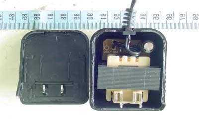
Click to zoom
Application Details
- Equipment Class
- TNF - Licensed Non-Broadcast Transmitter Held to Face
- Date of Grant
- Jan 05, 2004
- Application Purpose
- Original Equipment
- Date of Application
- Jan 05, 2004
- Equipment Note
- Handheld Wireless Microphone Transmitter
- Frequency Range
- 790.00000000 - 806.00000000
- Company
- Mascot Electric Co., Ltd.
- Country
- Taiwan
Documents & Files
Document Text
Text extracted from the exhibit documents filed with the FCC. Open a document above to read the original.
Users Manual
USER’S MANUAL BAND DIVERSITY WIRELESS MICROPHONE SYSTEM WIRELESS MICROPHONE SYSTEM 1. Introduction ........................................................................... 1 2. Safety .................................................................................... 1 3. Environment ........................................................................... 1 4. Wireless Note...................................................................... 1 5. Product Description ................................................................. 5.1 Receivers 5.2 Handheld Microphone 5.3 Bodypack Transmitter 2 6. Basic Connections.................................................................... 5 7. Setting Up ............................................................................ 7.1 Connecting the receiver to power. 7.2 Connecting the receiver to an audio mixer or an amplifier. 7.3 Inserting batteries into the handheld / bodypack transmitter 7.4 Setting up the handheld transmitter 7.5 Setting up the bodypack transmitter 7 8. Trouble-shooting .................................................................... 8 9. System Feature...................................................................... 9 10. System Specification............................................................ 9 Table of Contents WIRELESS WIRELESS NOTE 1 FCC Statement This device complies with part 15 of the FCC rules. Operation is subject to the following two conditions: (1)This device may not cause harmful interference and (2) This device must accept any interference received, including interference that may cause undesired operation Notice : The changes or modifications not expressly approved by the party responsible for compliance could void the user’s authority to operate the equipment. IMPORTANT NOTE: To comply with the FCC RF exposure compliance requirements, no change to the antenna or the device is permitted. Any change to the antenna or the device could result in the device exceeding the RF exposure requirements and void user’s authority to operate the device. 1. Introduction Thank you for purchasing our product. This wireless microphone system operates in UHF band frequency with synthesizer controlled. The system with 16 or 64 selectable frequencies via Phase Locked Loop (PLL) circuitry makes it easy to choose non-interfered channels. Please read this instruction manual carefully before operating the system. This manual covers the function and operation of the wireless microphone system. 2. Safety ÿ Do not spill liquid on the appliance and do not drop it on a hard concrete floor. ÿ Do not place the appliance near heat sources such as radiators, amplifier, or etc. Do not expose it to direct sunlight, extremely dust, excessive moisture, or vibration. ÿ Take out the battery from transmitter, if the appliance has been not used for a longer period. This will avoid the damage resulting from a defective leaking battery 3. Environment ÿ Do not throw used batteries into a fire or garbage bin with domestic rubbish. Be sure to dispose of used batteries in accordance with local waste disposal rules. ÿ When disposing the equipment, remove the batteries, separate the case, circuit boards, and cables, and dispose of all components in accordance with local waste disposal rules. 4. Wireless Note ÿ Before setting up, make sure that the transmitter and receiver are tuned to the same frequency. ÿ Do not use two transmitters in the same frequency. ÿ Use good quality batteries to avoid the damage resulting from a defective leaking battery. ÿ Turn the volume control on the receiver to adjust receiver output level to match input level requirements of a mixer or amplifier.(Please see 7.2) ÿ While checking sound, move the transmitter around the area where you use the system to look for dead spots. If you find any dead spot, change the receiver position. If it does not work, avoid such places. ÿ To avoid interference, do not put the receiver too near metal object and avoid obstructions between transmitter and receiver. ÿ Avoid the interference from TV, radio, other wireless appliances and etc. Wireless Microphone ̈ ≠ Æ Ø ∞ ± ≤ ≥ ¥ 11 15 13 14 2 5. Product Description 5.1 Receivers This is a stationary diversity receiver for use with our 16- or 64-channel selectable transmitters. The receiver operates in UHF band frequency with PLL synthesized control. Powered by 12V DC. 1. Power: Pushes the receiver on and off. 2. Group LED Display: Displays group number. 3. Channel LED Display: Displays channel number. ¥ μ 12 Wireless Microphone WIRELESS PRODUCT DESCRIPTION DC 12V 500mA AUDIO OUTPUT UNBALANCEDBALANCEDSQUELCH or FOR CHARGER O P E N WIRELESS PRODUCT DESCRIPTION 3 4. Group Button: Press this button to choose a displayed group number and the setting group will be locked in 5 seconds. 5. Channel Button: Press this button to choose a displayed channel number and the setting channel will be locked in 5 seconds. 6. Set Button: Press this button to choose a displayed group or channel number. 7. RF Level Indicators: Five LEDs per RF antenna channel glow to indicate RF signal strength. The more LEDs that glow, the stronger the received signal. If none of these LEDs glow, no signal is being received. 8. Level Control: This rotary control adjusts the receiver output level to match the input sensitivity of an audio mixer or amplifier 9. Antenna: Fixed-length UHF antenna permanently mounted on rear panel. 10. Balanced Output: 3-pin XLR connector provides balanced low-impedance output 11. Unbalanced Output: 6.3j phone jack provides unbalanced low-impedance output 12. Squelch: The squelch adjusts the output level to suppress the noise. Setting the squelch too high will reduce the usable range of the system. Set the squelch to minimum before turning the receiver on. 13. DC IN: Input connector for the supplied AC adapter. 14. Charger Input: Connect the supplied cable to the receiver and the microphone, and it takes around 10 hours to recharge and…
Text truncated - open the document above for the full version.
Cover Letter(s)
910805 2 Federal Communications Commission Authorization Agreement Dear Sir: We, the undersigned, hereby authorize ELECTRONICS TESTING CENTER, TAIWAN to act on our behalf in all matters relating to application forWireless Handheld Transmitter Microphone ( Model :UF-18, FCC ID : JEBUF-18C )authorization, including the signing of all documents relating to these matters. Any and all acts carried out by ELECTRONICS TESTING CENTER, TAIWAN on our behalf shall have the same effect as acts of our own. The applicant certifies that in the case of an individual applicant ( e.g., corporation ), no party to the applicant is subject to a denial of federal benefits, that includes FCC benefits, pursuant to section 5301 of the Anti-drug abuse Act of 1988, 21 U.S.C. 862. For a definition of a “party” for these purposes See 47 C.F.R. 1.2002(b). By: Chiang, Kun-Tien By: (Signature) (Printed) Title : President Applicant : MASCOT ELECTRIC CO., LTD. Address : No. 85 Chang Hsing First Street, Tai-tzu Village, Jen-Te Hsian, Tainan Hsien, Taiwan Tel : +886-6-2710171 Fax: +886-6-2710808 Date : Nov., 28, 2003 910805 3 Federal Communications Commission FCC ID: JEBUF-18C Dear Sir: This is to request confidentiality on information submitted for above application. We would like to request confidentiality on some exhibits we submitted for above original application for the reason of trade secret. If those exhibits are available for public inspection, any person who once gets the information contained in those exhibits will be able to design and to make the same products very easily. This is a very serious problem and huge loss for us, because we did invest so much on it. Please be not made the Exhibit Types listed below routinely available for public inspection: Block Diagram and Schematics. By: Chiang, Kun-Tien By: (Signature) (Printed) Title : President Applicant : MASCOT ELECTRIC CO., LTD. Address : No. 85 Chang Hsing First Street, Tai-tzu Village, Jen-Te Hsian, Tainan Hsien, Taiwan Tel : +886-6-2710171 Fax: +886-6-2710808 Date : Nov., 28, 2003
ID Label/Location Info
M a d e i n T a i w a n F C C I D . : J E B U F - 1 8 C M o d e l : U F - 1 8 F C C 認 證 貼 紙 黑 底 白 字 PDF created with FinePrint pdfFactory trial version http://www.fineprint.com
Internal Photos
ETC Report No.:ET92R-11-041-01 FCC ID.:JEBUF-18C Rev. 2.0 CONSTRUCTED PHOTOS of EUT Internal View of EUT Internal View of EUT ETC Report No.:ET92R-11-041-01 FCC ID.:JEBUF-18C Rev. 2.0 CONSTRUCTED PHOTOS of EUT Component View of PCB Component View of PCB ETC Report No.:ET92R-11-041-01 FCC ID.:JEBUF-18C Rev. 2.0 CONSTRUCTED PHOTOS of EUT Component View of PCB Solder View of PCB ETC Report No.:ET92R-11-041-01 FCC ID.:JEBUF-18C Rev. 2.0 CONSTRUCTED PHOTOS of EUT Internal View of Adaptor ETC Report No.:ET92R-11-041-01 FCC ID.:JEBUF-18C Rev. 2.0 CONSTRUCTED PHOTOS of EUT Component View of Adaptor’s PCB Solder View of Adaptor’s PCB
Operational Description
The handheld microphone operates in UHF band frequency with PLL synthesized control. UHF 16 or 64 preprogrammed selectable frequencies to avoid interference. Uni-directional dynamic or uni-directional condenser capsules with different characters for various choices. Use 1.5V x 2 AA size batteries for low operating cost.
Parts List/Tune Up Info
UF-18 TRANSMITTER PROCEDURE 1. Audio from the microphone is coupled through IC BA4510 applied to Audio amplifier and buffer stages. Adjust VR1 to control audio amplify level. 2. D1(Variable Capacitance Diode) of the VCO modulate the audio signal into RF signal 3. The RF signal of 682MHz to 698MHz is generated from VCO and is locked via PLL IC U4 when selected. Adjust VC C31 to correct the exact frequency. The RF level at this stage is about –15dBm. 4. The locked RF signal is coupled to bufferQ8and amplifiers Q9 & Q5. 5. After RF pre-amplify and final amplify,L4,L8,C63 & L11,C76 to filter the spurious and harmonics and have the correct frequency pass through the maximum pass-point of the filter to transmit out. At this stage, the RF level is about 7dBm. MASCOT ELECTRIC CO, LTD DATE NOV 11 2003 UF-18 TRANSMITTER PROCEDURE 1. Audio from the microphone is coupled through IC BA4510 applied to Audio amplifier and buffer stages. Adjust VR1 to control audio amplify level. 2. D1(Variable Capacitance Diode) of the VCO modulate the audio signal into RF signal 3. The RF signal of 740MHz to 752MHz is generated from VCO and is locked via PLL IC U4 when selected. Adjust VC C31 to correct the exact frequency. The RF level at this stage is about –15dBm. 4. The locked RF signal is coupled to bufferQ8and amplifiers Q9 & Q5. 5. After RF pre-amplify and final amplify,L4,L8,C63 & L11,C76 to filter the spurious and harmonics and have the correct frequency pass through the maximum pass-point of the filter to transmit out. At this stage, the RF level is about 7dBm. MASCOT ELECTRIC CO, LTD DATE NOV 11 2003 UF-18 TRANSMITTER PROCEDURE 1. Audio from the microphone is coupled through IC BA4510 applied to Audio amplifier and buffer stages. Adjust VR1 to control audio amplify level. 2. D1(Variable Capacitance Diode) of the VCO modulate the audio signal into RF signal 3. The RF signal of 790MHz to 806MHz is generated from VCO and is locked via PLL IC U4 when selected. Adjust VC C31 to correct the exact frequency. The RF level at this stage is about –15dBm. 4. The locked RF signal is coupled to bufferQ8and amplifiers Q9 & Q5. 5. After RF pre-amplify and final amplify,L4,L8,C63 & L11,C76 to filter the spurious and harmonics and have the correct frequency pass through the maximum pass-point of the filter to transmit out. At this stage, the RF level is about 7dBm. MASCOT ELECTRIC CO, LTD DATE NOV 11 2003
Test Report
Rev. 2.0 FCC Part 74 Subpart H EMI TEST REPORT of E.U.T. : Wireless Handheld Transmitter Microphone FCC ID. : JEBUF-18C MODEL : UF-18 Working Frequency : 682MHz-806MHz for APPLICANT : MASCOT ELECTRONIC CO., LTD. ADDRESS : No. 85 Chang Hsing First Street, Tai-tzu Village, Jen-Te Hsian, Tainan Hsien, Taiwan, R.O.C. Test Performed by ELECTRONICS TESTING CENTER, TAIWAN NO. 34, LIN 5, DING FU TSUN, LINKOU HSIANG TAIPEI HSIEN, TAIWAN, R.O.C. Tel:(02)226023052 Fax:(02)26010910 http://www.etc.org.tw ; e-mail : [email protected] Report Number : ET92R-11-041-01 ETC Report No.:ET92R-11-041-01 FCC ID.: JEBUF-18C Rev. 2.0 TEST REPORT CIRTIFICATION Applicant : MASCOT ELECTRONIC CO., LTD. No. 85 Chang Hsing First Street, Tai-tzu Village, Jen-Te Hsian, Tainan Hsien, Taiwan, R.O.C. Manufacturer : MASCOT ELECTRONIC CO., LTD. No. 85 Chang Hsing First Street, Tai-tzu Village, Jen-Te Hsian, Tainan Hsien, Taiwan, R.O.C. Description of EUT : a) Type of EUT : Wireless Handheld Transmitter Microphone b) Trade Name : MASCOT c) Model No. : UF-18 d) FCC ID : JEBUF-18C e) Working Frequency : 682MHz-806MHz f) Power Supply : DC 3V Batteries Regulation Applied : FCC Rules and Regulations Part 74 Subpart H (2001) I HEREBY CERTIFY THAT; The data shown in this report were made in accordance with the procedures given in ANSI C63.4 and the energy emitted by the device was founded to be within the limits applicable. I assume full responsibility for accuracy and completeness of these data. Issued Date : Dec. 12, 2003 Test Engineer : ( Tien Lu Liao ) Approve & Authorized Signer : Will Yauo, Manager EMC Dept. II of ELECTRONICS TESTING CENTER, TAIWAN ETC Report No.:ET92R-11-041-01 FCC ID.: JEBUF-18C Rev. 2.0 Table of Contents Page 1. GENERAL INFORMATION ............................................................................................................................... 1 1.1 P RODUCT D ESCRIPTION .......................................................................................................................................... 1 1.2 C HARACTERISTICS OF D EVICE : ...............................................................................................................................1 1.3 T EST M ETHODOLOGY ............................................................................................................................................. 1 1.4 T EST F ACILITY ........................................................................................................................................................ 1 2. REQUIREMENTS OF PROVISIONS ................................................................................................................ 2 2.1 D EFINITION ............................................................................................................................................................. 2 2.2 F REQUENCIES A VAILABLE ...................................................................................................................................... 2 2.3 R EQUIREMENTS FOR R ADIO E QUIPMENT ON C ERTIFICATION .................................................................................. 2 2.4 L ABELING R EQUIREMENT ....................................................................................................................................... 3 3. OUTPUT POWER MEASUREMENT ................................................................................................................ 4 3.1 P ROVISION A PPLICABLE ......................................................................................................................................... 4 3.2 M EASUREMENT P ROCEDURE ................................................................................................................................... 4 3.3 T EST D ATA ............................................................................................................................................................. 6 3.4 R ESULT C ALCULATION ........................................................................................................................................... 9 3.5 T EST E QUIPMENT .................................................................................................................................................... 9 4. MODULATION CHARACTERISTICS ........................................................................................................... 10 4.1 P ROVISIONS A PPLICABLE ...................................................................................................................................... 10 4.2 M EASUREMENT M ETHOD ...................................................................................................................................... 10 4.3 M EASUREMENT I NSTRUMENT ...............................................................................................................................11 4.4 M EASUREMENT R ESULT ....................................................................................................................................... 11 5. OCCUPIED BANDWIDTH OF EMISSION .................................................................................................... 17 5.1 P ROVISIONS A PPLICABLE ...................................................................................................................................... 17 5.2 M EASUREMENT M ETHOD ...................................................................................................................................... 17 5.3 O CCUPIED B ANDWIDTH T EST E QUIPMENT ............................................................................................................ 17 5.4 B ANDWIDTH M EASURED ...................................................................................................................................... 18 5.4.1 I NPUT L EVEL D ERIVED ....................................................................…
Text truncated - open the document above for the full version.
Test Setup Photos
ETC Report No.:ET92R-11-041-01 FCC ID.:JEBUF-18C Rev. 2.0 Radiated Measurement Photos ETC Report No.:ET92R-11-041-01 FCC ID.:JEBUF-18C Rev. 2.0 (Charge) ETC Report No.:ET92R-11-041-01 FCC ID.:JEBUF-18C Rev. 2.0 Photos of Conduction Measuring Setup
Contact Information
Applicant
Chia-Yu Chiang(President)
Test Firm
Electronics Testing Center, TaiwanWin-Po Tsai
Technical Specifications
| # | Rule Parts | Frequency Range | Power Output | Emission | Tolerance |
|---|---|---|---|---|---|
| 3 | 74 | 790 MHz - 806 MHz | 5.50 mW | 161KF3E | 0.005 % |
Other Applications from Mascot Electric Co., Ltd.

JEBUF-9R1
Jul 04, 2023Handheld Microphone
Equipment Class
DWM - Part 15 Wireless Microphone
JEBDR-024
May 23, 2021Receiver
Equipment Class
DTS - Digital Transmission System
JEBDF-024
May 15, 2021Handheld Microphone
Equipment Class
DTS - Digital Transmission System
JEBDB-024
May 15, 2021Bodypack Transmitter
Equipment Class
DTS - Digital Transmission System
JEBUT-51B
Mar 30, 2020Bodypack Transmitter
Equipment Class
DWM - Part 15 Wireless Microphone