JJ4TCG001Projector RF Remote Control
Movea, Inc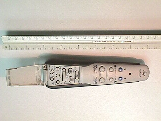
Click to zoom
Application Details
- Equipment Class
- DXX - Part 15 Low Power Communication Device Transmitter
- Date of Grant
- Mar 11, 2001
- Application Purpose
- Original Equipment
- Date of Application
- Mar 11, 2001
- Equipment Note
- Projector RF Remote Control
- Frequency Range
- 49.83000000 - 49.90000000
- Company
- Movea, Inc
- Country
- United States
Documents & Files
Document Text
Text extracted from the exhibit documents filed with the FCC. Open a document above to read the original.
Cover Letter(s)
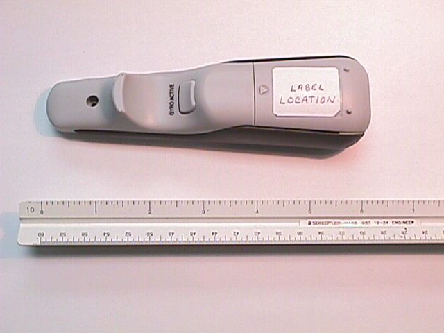
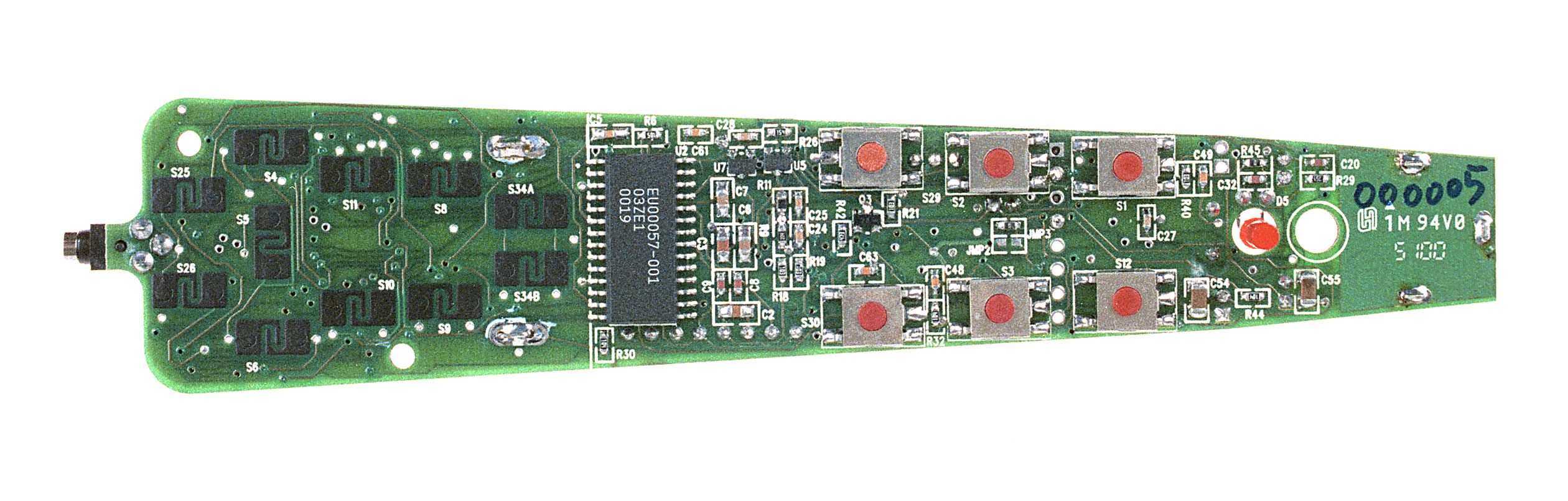
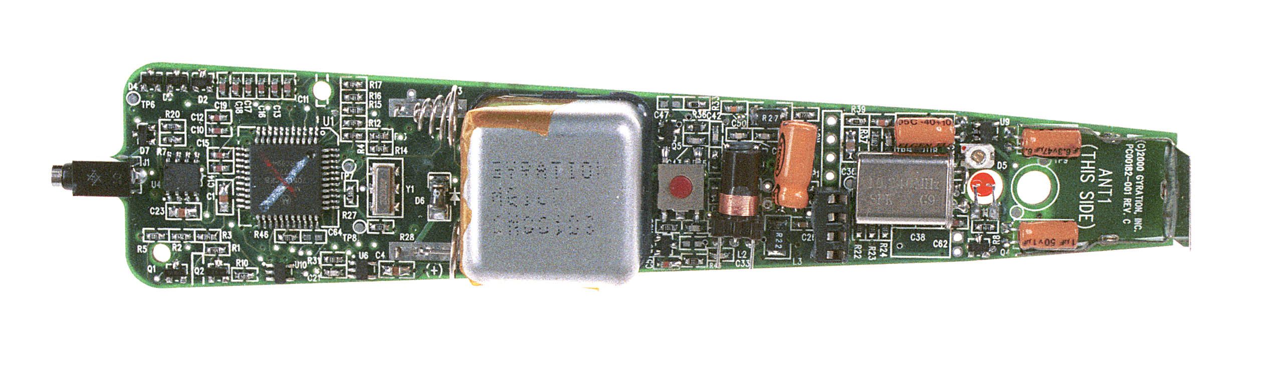
American Telecommunications Certification Body Inc. 6731 Whittier Ave, McLean, VA 22101 March 2, 2001 TO: Mark Hill RE: Gyration FCC ID: JJ4TCG001 Mark, I have a couple of comments about the application. 1.) The internal photographs are a bit fuzzy. I do not believe they will be unacceptable to the Commission. Please address. See 2.1033(7) for guidance. 2.) The Test Setup photos don’t provide a heck of a lot of information on the device as it was tested. Please provide new photographs showing it’s positioning on the table relative to the search antenna. In addition, Test Setup photos must be supplied to a separate “bucket” at the Commission. In the future please provide the photos to me as a separate document. 3.) 15.235(a) specifies the field strength is to be reported as average, not Quasi-Peak as your EMC Test Data report indicates on pp. 5 of 6. 4.) 15.235(b) specifies all signals exceeding 20uV/m shall be reported. This is different than what is usually required by 15.31(o). Has this been done? Has it been done to the frequency range specified in 15.33(a)(1) and (4)? Loved the Circuit Description. All applications should have one this good. William H. Graff Examining Engineer President and Director of Engineering The items indicated above must be submitted before processing can continue on the above referenced application. Failure to provide the requested information within 30 days of the original e-mail date may result in application dismissal pursuant to Section 2.917(c). Correspondence should be considered part of the permanent submission and may be viewed from the Internet after a Grant of Equipment Authorization is issued. Please do not reply to this correspondence using the email reply button. In order for your response to be processed expeditiously, you must attach your answers to email correspondence. Reply to the examiner at the email address shown below. Also, please note that partial responses increase processing time and should not be submitted. Any questions about the content of this correspondence should be directed to the e-mail address listed below the name of the sender.
Cover Letter(s)
From: dave guidotti [[email protected]] Sent: March 02, 2001 4:30 PM To: William Graff Subject: Re: Gyration JJ4TCG001 Bill, We are working on items 1 and 2, we will be submitting photos shortly. Item 3: Elliott incorrectly put the QP reading in the report on page 5. On page 22 of the technical report there is radiated emissions data showing both the peak and QP readings being well under the limit. This should satisfy the Average reading requirement. Let us know if we need to update our technical report to show the peak data. Item 4: You asked if all emissions exceeding 20 uV/m were reported. The answer is Yes. A preliminary scan was performed in an anechoic chamber over the frequency range 30 MHz to 1 GHz before going out to the open site. I'm glad you like the circuit description, You have no idea how difficult it was to get that. At 10:22 AM 3/2/2001 -0700, you wrote: >Mark, > >Attached I have my comments on this application. > >Also, save yourself a bit of time on the 731 Application. The microprocessor >and power output are not required (unless RF exposure is involved >i.e.15.247). > >~~~~~~~~~~~~~~~~~~~~~~~~~~~~~~~~ >~ William H. Graff, NARTE Certified >~ President and Director of Engineering >~ AmericanTCB, Inc. >~ 6731 Whittier Ave >~ McLean, VA 22101 >~ mailto:[email protected] >~ mobile mailto:[email protected] >~ Direct Phone: (480)317-0683 >~ Direct Mobile: (602)790-6788 >~ Corporate Phone: (703)847-4700 >~ Corporate FAX: (703) 847-6888 >~~~~~~~~~~~~~~~~~~~~~~~~~~~~~~~~ David Guidotti Documentation Specialist Elliott Laboratories, Inc. Ph: 408-245-7800 ext. 270 Fax: 408-245-3499 [email protected]
Operational Description
MillenniumProjectorRemoteTheoryofOperation1.doc 1/15/2001 Page 1 of 1 Theory of Operation Gyration, Inc. Millennium Series Projector RF Remote Model RRMCG1631CESA January 15, 2001 The Millennium Series Projector Remote consists of a 40 or 49 MHz (49 MHz for United States, 40 MHz for other countries.) electrical assembly (including gyro) mounted in a compact ABS plastic remote control housing. A battery compartment (with slide-off cover) containing four AAA-sized alkaline cells is located in the underside of the handle portion of the housing. The top of the housing contains a number of exposed push buttons with custom printed legends allowing for customized applications, plus an additional group buttons hidden beneath a hinged cover. A single LED indicator mounted on the top side of the remote near the tip farthest from the user can be programmed to flash in a number of different ways depending upon OEM requirements. The pc board in the Projector Remote consists of an 8-bit CPU (U1) with internal masked ROM memory and an external EEPROM (U4) surrounded by associated power supply and switch matrix scanning circuitry, plus an FSK RF transmitter. Information concerning motion originates with the gyro assembly (U3). The output from the gyro is processed by a custom ASIC (U2) and relayed via serial peripheral interface to the CPU. The RF transmitter consists of a dual PLL synthesizer (U8) and a 40/49 MHz VCO (Voltage Controlled Oscillator) (Q7, Q5) plus an RF output amplifier/filter section. The output from this transmitter is connected to a short end-loaded monopole antenna located at the top (away from user) end of the pc board. The VCO consists of a varactor (D8) tuned Colpitts oscillator (Q7, L1, C39, C45) plus a buffer stage (Q5). Both Q7 and Q5 operate in the emitter follower configuration. The PLL synthesizer operates with a reference frequency determined by 10.24 MHz crystal Y2. The 10.24 MHz reference oscillator is frequency modulated by pulling the crystal frequency downward with a parallel capacitance (C46) switched in and out of circuit with a bipolar transistor (Q4). Q4 is in turn switched on and off at a rate corresponding to 4800 bits per second (bps) by the tx data output from the CPU. The RF signal generated by the VCO thus becomes modulated to a level of 2.4 KHz deviation, representing a minimum shift keying (MSK) condition for 4800 bps binary FSK signaling (BT = 0.5). The 40/49 MHz VCO output at the emitter of Q5 branches off into two separate directions. The first branch (via C43) is sent back to the PLL in order to provide an output reference for frequency/phase comparison. The second branch (via C40) is sent onward to the RF output stage (Q6) and then on to the antenna via a matching network. The antenna matching network (consisting of L2, C33, C56, C53, C52 and C57) also functions as a transmitting filter to reduce the radiated harmonic output levels in order to meet emission limits imposed by government regulations. The power supply section consists of a 4-cell (6 VDC) alkaline battery pack, a reverse polarity protection diode (D6), a fixed 4.0 VDC linear low-dropout regulator U7 (supply for CPU -- always on) and a fixed 3.3 VDC linear low- dropout regulator with external on/off control (U9). The 3.3V supply is used to power the VCO and PLL sections only and is shut off when the transmitter is not turned on. Low voltage detector U5 resets the CPU during conditions of insufficient pack voltage (about 1 V per cell), thus eliminating the possibility of out-of-spec transmitter operation at low battery voltages.
Test Report
File: R41641 January 23, 2001 AmericanTCB, Inc. 6731 Whittier Avenue McLean, VA 22101 Gentlemen: The enclosed documents constitute a formal submittal and application for a Grant of Equipment Authorization pursuant to Subpart C of Part 15 of FCC Rules (CFR 47) regarding intentional radiators. Data within this report demonstrates that the equipment tested complies with the FCC limits for intentional radiators. Elliott Laboratories, as duly authorized agent prepared this submittal. A copy of the letter of our appointment as agent is enclosed. If there are any questions or if further information is needed, please contact Elliott Laboratories for assistance. Sincerely, Mark E. Hill Manager, EMC Consulting Services MEH/dmg Enclosures: Agent Authorization Letter Emissions Test Report with Exhibits File: R41641 Page 1 of 13 Electromagnetic Emissions Test Report and Application for Grant of Equipment Authorization pursuant to FCC Part 15, Subpart C Specifications for an Intentional Radiator on the Gyration, Inc. Model: Projector RF Remote Control FCC ID: JJ4TCG001 GRANTEE: Gyration, Inc. 12930 Saratoga Avenue, Suite C-6 Saratoga, CA. 95070 TEST SITE: Elliott Laboratories, Inc. 684 W. Maude Avenue Sunnyvale, CA 94086 REPORT DATE: January 23, 2001 FINAL TEST DATE: January 18, 2001 AUTHORIZED SIGNATORY: ______________________________ Mark E. Hill Manager, EMC Consulting Services This report shall not be reproduced, except in its entirety, without the written approval of Elliott Laboratories, Inc. Elliott Laboratories, Inc. -- EMC Department Test Report Report Date: January 23, 2001 File: R41641 Page 2 of 13 pages TABLE OF CONTENTS COVER PAGE.....................................................................................................................................................1 TABLE OF CONTENTS...................................................................................................................................2 SCOPE...............................................................................................................................................................4 OBJECTIVE......................................................................................................................................................4 STATEMENT OF COMPLIANCE..................................................................................................................4 EMISSION TEST RESULTS............................................................................................................................5 LIMITS OF CONDUCTED INTERFERENCE VOLTAGE.............................................................................5 LIMITS OF RADIATED INTERFERENCE FIELD STRENGTH...................................................................5 MEASUREMENT UNCERTAINTIES............................................................................................................6 EQUIPMENT UNDER TEST (EUT) DETAILS..............................................................................................7 GENERAL......................................................................................................................................................7 ENCLOSURE.................................................................................................................................................7 MODIFICATIONS..........................................................................................................................................7 SUPPORT EQUIPMENT................................................................................................................................7 EXTERNAL I/O CABLING............................................................................................................................7 TEST SOFTWARE.........................................................................................................................................7 TEST SITE.........................................................................................................................................................8 GENERAL INFORMATION..........................................................................................................................8 RADIATED EMISSIONS CONSIDERATIONS.............................................................................................8 MEASUREMENT INSTRUMENTATION......................................................................................................9 RECEIVER SYSTEM.....................................................................................................................................9 INSTRUMENT CONTROL COMPUTER.......................................................................................................9 LINE IMPEDANCE STABILIZATION NETWORK (LISN)..........................................................................9 POWER METER...........................................................................................................................................10 FILTERS/ATTENUATORS...........................................................................................................................10 ANTENNAS..................................................................................................................................................10 ANTENNA MAST AND EQUIPMENT TURNTABLE.................................................................................10 INSTRUMENT CALIBRATION....................................................................................................................10 TEST PROCEDURES......................................................................................................................................11 EUT AND CABLE PLACEMENT.................................................................................................................11 RADIATED EMISSIONS.........................…
Text truncated - open the document above for the full version.
Test Setup Photos
Elliott Laboratories, Inc. -- EMC Department Test Report Report Date: March 9, 2001 File: R41641 EXHIBIT 3: Test Configuration Photographs Elliott Laboratories, Inc. -- EMC Department Test Report Report Date: March 9, 2001 File: R41641
Contact Information
Applicant
Tim Kelliher(Movea engineering Director)
Technical Contact
Gyration, Inc.Dan DeVaul
[email protected]408 255 3016
12930 Saratoga Avenue · Saratoga, Florida · United States
Test Firm
Elliott Laboratories LLCDavid Bare
Technical Specifications
| # | Rule Parts | Frequency Range | Power Output |
|---|---|---|---|
| 1 | 15C | 49.83 MHz - 49.9 MHz | - |
Other Applications from Movea, Inc

JJ4-MCTL3
Jul 26, 2011WIRELESS MOTION MEASUREMENT UNIT-CONTROLLER
Equipment Class
DXT - Part 15 Low Power Transceiver, Rx Verified
JJ4-AS04130
Sep 28, 2010In-Air Wireless Optical Laser Computer Mouse
Equipment Class
DTS - Digital Transmission System
JJ4-AS04126
Apr 08, 2010Wireless Keyboard
Equipment Class
DXX - Part 15 Low Power Communication Device Transmitter
JJ4-TT2
Sep 17, 2006Transceiver
Equipment Class
DTS - Digital Transmission System
JJ4-DD2
Apr 16, 2006Transceiver
Equipment Class
DTS - Digital Transmission System