JPADMEH2AVIATION SERVICES DME TRANSMITTER
Indra Air Traffic Inc.
Click to zoom
Application Details
- Equipment Class
- TNB - Licensed Non-Broadcast Station Transmitter
- Date of Grant
- Oct 16, 2006
- Application Purpose
- Original Equipment
- Date of Application
- Oct 15, 2006
- Equipment Note
- AVIATION SERVICES DME TRANSMITTER
- Frequency Range
- 960.00000000 - 1215.00000000
- Company
- Indra Air Traffic Inc.
- Country
- United States
Documents & Files
Document Text
Text extracted from the exhibit documents filed with the FCC. Open a document above to read the original.
Users Manual
1.INSTALLATION, INTEGRATION AND CHECKOUT 1.1 Introduction This section contains installation information for the independently located DME. If the DME is to be collocated with VOR or ILS refer to the basic instructions in this section and to the installation instructions for the VOR or ILS equipment. With respect to general requirements, a good VOR or ILS site will satisfy the DME requirements as well. System performance must be verified by flight inspection. Figure 1-1 shows a typical DME site. NOTE After flight inspections and prior to use by pilots, it is mandatory that the monitor be left in control of the facility and not in bypass. 1.2 Site Information 1.2.1 Site Selection The signal radiated from the DME is affected by obstructions and terrain in the immediate vicinity of the antenna and by obstructions and terrain within the service range of the station. An ideal site would be the highest ground in the vicinity with level terrain, cleared of all objects for a radius of at least 3000 feet (915 meters), and with no obstructions extending above the horizontal plane of the antenna within the service range of the station. In most localities, it is not possible to satisfy the ideal site requirements. Every effort must be made to obtain the best site available. Although no absolute minimum requirements can be stated, a site is normally acceptable if it meets the recommendations contained in the following paragraphs. 1.2.1.1 Terrain Features The terrain should be level within a radius of 200 feet (61 meters). In a radius between 200 and 1000 feet (61 and 305 meters), a downward slope is acceptable if (1) the rate of descent is not more than 4 feet in 100 feet (1.22 meters in 30.5 meters) and (2) contour lines are generally circular around the site. Beyond a radius of 1000 feet (305 meters), terrain should be below the horizontal plane of the antenna. 1.2.1.2 Obstructions There should be no structures within 750 feet (229 meters) of the antenna. Metallic structures should not subtend vertical angles greater than 1.2 degrees as measured from the antenna. Wooden structures with negligible metal content should not subtend vertical angles greater than 2.5 degrees as measured from the antenna. Structures having considerable length (such as aircraft hangers or administration buildings) should be situated lengthwise on a radial from the antenna. Single trees less than 35 feet (11 meters) high may be tolerated beyond 750 feet. No group of trees or groves may be within 1000 feet. No overhead power or control lines are permissible within 750 feet of the antenna. Figure 1-1 Typical DME Site 1.2.2 Shelter Requirements The shelter location depends primarily on the maximum cable run allowed and on the desired location for the DME antenna. An RF transmission line of 2" foamflex cable (with Type N connectors at each end), one cable for the monitor antenna made up of 1/4" foamflex (with a Type N connector at one end and a TNC male connector at the opposite end), and one AC cable for the OB Lite may be supplied with the DME equipment. These cables are 35 feet long. When the requirements exceed 35 feet, company engineering personnel can provide the necessary planning to determine the requirements. The DME ground equipment is designed to operate continuously and unattended, but space must be allocated for maintenance personnel and their equipment. 1.3 Unpacking and Repacking The DME electronic subsystem is shipped unassembled. Only general precautions can be given because the crating and unpacking depends upon destination and what optional equipment is included. Most items are packed separately in individual containers; these are then grouped for crating. Each crate contains a packing list which details what equipment is enclosed in the crate. Unpack the equipment and visually inspect each item for accuracy and damage, but DO NOT REMOVE any ESD protective wrapping. Report any damage immediately. After inspection, repack each item to prevent damage. During installation, unpack items as they are needed. 1.3.1 Environmental Considerations The environmental conditions must not exceed those listed in the Specifications of Table 1-1 Error! Reference source not found.. 1.4 Input Power Requirement Summary The requirements for input power must not exceed those listed in the Specification of Table 1-1 Error! Reference source not found.. 1.5 Installation Procedures 1.5.1 Installation Tools and Test Equipment Refer to Error! Reference source not found.for a list of test equipment and Table 1-1 for a list of special tools required for installation. Table 1-1 Special Tools Required for Installation Description Tube Cutter File Knife 2-1/4" Hole Saw Assorted Screw Drivers and Wrenches Thread Tape 1.5.2 Installation Kits Refer to Table 1-2 for all component or modification kits required to install the DME station. Some kits listed are optional equipment. Kits ending with “X” have many different varieties and will vary depending on the site specific requirements. In all necessary cases installation drawings for each kit are provided with the kit hardware. Table 1-2 Component or Modification Kits Required to Install the DME Part Number Description 470085-000X DME Tower Antenna Kit 470561-0001 DME Unidirectional GS Tower Mount Antenna Kit 470628-000X DME Battery Backup Kit, 35AHr 470622-0001 DME Accessory Kit 470627-0001 DME AC Power/Installation Kit 470291-000X DME OB Light Kit 470623-0001 Environmental Sensors Kit 470360-000X PMDT Kit Table 1-3 Additional kits required to Install Shelter and Tower Grounding Systems Part Number Description 470252-0002 Civil Install Kit, 45G Rohn Tower 470225-0001 Civil Install Kit, Shelter 470557-0001 Shelter Internal Grounding Kit 1.5.3 Shelter Foundation Installation For shelters not supplied by SELEX Sistemi Integrati Inc., the manufacturer of the shelter will supply drawings for the site engineer. 1.5.4 Shelter Installation a. Use a crane and four nylon slings (20 feet long) to position t…
Text truncated - open the document above for the full version.
Users Manual
1. TECHNICAL DESCRIPTION 1.1 Introduction This section contains a technical description of the single and dual 2160 and 2170 DME. This includes, simplified system block diagram theory and block diagram and detailed circuit theory of the Circuit Card Assemblies (CCA) contained in the system. 1.2 DME Operation Principles Refer to Figure 1-1. The DME system requires a single-channel receiver-transmitter combination (transponder beacon) in conjunction with a special omni-directional antenna as the ground station, and a multichannel receiver-transmitter combination (interrogator) on board the aircraft. One multichannel airborne receiver-transmitter (transmitting and receiving coded, pulsed information) provides both the distance and identification functions. The DME system has 252 operating channels, with the adjacent channels spaced one megahertz apart. For air-to-ground transmission (interrogation), there are 126 channels within the frequency band of 1025 MHz to 1150 MHz. For ground-to-air transmission (reply), there are 63 channels in the frequency of 960 MHz to 1024 MHz, plus 63 channels in the frequency band of 1151 MHz to 1215 MHz. The DME system utilizes pulse-coding techniques in the transmission of its intelligence. The transmissions are composed of pulse groups with a prearranged spacing between the pulses of the group. For X- Channels, the interrogation pulses and the transponder reply pulses are both spaced 12 μs apart. For Y- Channels, the interrogation pulses are spaced at 36 μs; and the transponder reply pulses are spaced at 30 μs. Both the interrogator and transponder receivers employ pulse decoders, which are set to pass only pulse pairs of the prescribed spacing. The purpose of the two-pulse technique is to increase the signal-to-noise ratio and to discriminate against pulse interference, such as might be produced by radar transmission and other extraneous sources of RF energy on the frequency. The intelligence supplied to the aircraft by the DME transponder is both identity and distance information. The identity information is necessary for the pilot to positively identify the station that has been selected. Identity information is provided to the aircraft approximately every 30 seconds. The distance information, however, is provided to the aircraft only upon demand. Each aircraft must interrogate the ground facility by means of the coded interrogation pulse pairs, before the transponder beacon can generate and transmit distance information. Figure 1-1 Basic X-Channel DME System Block Diagram Refer to Figure 2-2. As stated, the transponder beacon must be interrogated by the aircraft before the ground facility can transmit usable distance information. Assuming an aircraft has interrogated the ground facility; the interrogation signal is received at the beacon antenna, and then routed to the receiver through the Circulator and Preselector. The signal is then amplified and fed to the Receiver Transmitter Controller (RTC) for verification of proper pulse spacing. Once receive pulses are validated the RTC encodes a reply with the proper pulse spacing and delay. The shaped pulses modulate the gated RF in the transmitter power amplifier (PA) to produce the RF output pulses. The output pulses are then sent to the antenna and radiated to the aircraft as reply pulse pairs. Figure 1-2 DME Transponder Block Diagram Three separate signals are transmitted by the beacon as a train of pulse pairs. These signals, in order of priority, are: identification, replies to interrogations, and squitter pulse pairs (used as fill-in pulses). This priority system prevents any interference between the three signals in the overall pulse train. The identification of the ground facility is important to the using aircraft; therefore, it has been assigned first priority in the priority system. The generation of identification intelligence is a function of the RTC. Identification is transmitted periodically in International Morse Code with the characters of the code consisting of a periodic train of pulse pairs. Identification keying occurs approximately every 30 seconds. When keyed, the priority logic circuit input is disabled; and the circuits will not accept any decodes from the receiver. The replies to an interrogation signal are second in the order of priority. Their induction into the pulse train must be controlled (to prevent interference with the identity cycle and to establish priority over the squitter pulses). This is accomplished by allowing them to enter the pulse train only during a time interval not occupied by the identity cycle. This is a major portion of the time, since the identity cycle only occurs approximately every 30 seconds. Once the receiver accepts an interrogation and decodes it, a blanking gate is generated (the so-called dead-time gate). The dead-time gate is used to inhibit the transponder decoder for approximately 60 μs. During this period, the decoded interrogation is delayed a predetermined amount of time and transmitted back as a reply. The total delay from the time of a received interrogation to transmission of a reply is typically set for 50 μs for an X-Channel DME. The squitter pulses are third in the order of priority. In the absence of interrogations or identity information, random squitter pulses are generated to maintain an average output pulse train of 800 Pulses Pairs Per Second (PPS). The purpose of transmitting squitter pulses is to stabilize the Automatic Gain Control (AGC) circuits in the aircraft interrogator. The process of distance measuring originates in the airborne unit with the generation and transmission of pulse signals called interrogations. The airborne transmitter repeatedly initiates and transmits pulse signals consisting of pulse pairs having 12 μs spacing, a pulse width of 3.5 μs, and a gaussian or sine-squared shape. These pulse pairs are recovered by the transponder beacon receiver, whose output triggers the associated transmitter into transmit…
Text truncated - open the document above for the full version.
Cover Letter(s)
October 11, 2006 Scot Rogers Rogers Labs Inc. SUBJECT: SELEX SISTEMI INTEGRATI INC. - FCC ID: JPADMEH2 REFERENCE: JOB 2786UC6 Dear MR. ROGERS: The following clarifications are provided to the FCC Type acceptance questions asked by the TCB. 1. The schematic provided under the Transmitter Schematic folder is for the Final amplifier only. Another set can be found under the Theory of Operation//Drawings. These schematics are for the frequency synthesizer and rf amplifiers. The set of schematics was reduced in number to limit the electronic submission to less then the required 3 Megabytes. I have attached the full set of schematics for your review. 2. The Test Procedure TS030802-0001 Tune.pdf requires that the amplifier module as a removable assembly produce 1260 Watts (or 61-dBm minimum). There are losses following this module due to: • Cables within equipment cabinet • Coaxial transfer relay • Isolator • Directional coupler for power measurement The specifications for this DME transmitter require the power at the output of the cabinet to be 1000 Watts so in order to overcome the loss of approximately 1 dB in the above items the module itself has to produce 1260 watts on the bench at the module output connector. The system level (complete product) test verifies that the output power is 1000 Watts at the cabinet output connector. 3. The current and voltage into the amplifier are expressed in average power not peak power. The average power into the amplifier module was measured to be 48 volts at 3.1 amps. This is an average power of 148.8 Watts. The module was producing 1000-Watts peak power at 2% duty cycle, which is equivalent to 20-Watts average. A peak current measurement was completed and the results are 67.2 Amps peak at 53.5 Volts. This results in 3595.2 watts peak 4. Please find the FAA reply letter attached. 5. Please find attached two pages from the Maintenance and Operation Manual with warning on the subject of radiation exposure. This is the same manual as the Low Power (100 W) so a similar warning was placed for that equipment also. The warning was added to the front of the manual and also in the Installation section. Kurt Rieke Navaid Product Manager Selex Sistemi Integrati Inc. 913-495-2666 [email protected]
Cover Letter(s)
October 2, 2006 Timco Engineering Inc. 849 NW State Road 45 Newberry, FL 32669 Office of Engineering and Technology Federal Communications Commission Columbia, MD 21046 Applicant: SELEX SISTEMI INTEGRATI INC. 11300 West 89th Street Overland Park, KS 66214 Re: Confidentiality for submittal information regarding FCC ID number JPADMEH2 PRODUCT: Aviation Services Transmitter (Distance Measuring Equipment). Dear Sirs: Short-term Pursuant to DA 04-1705 of the Commission’s pubic notice, we request short-term confidential treatment for the following information until 45 days after the Grant Date of Equipment Authorization in order to ensure sensitive business information remains confidential until the actual marketing of the device: External Photos, file Selex 1119A DME External Photos.jpg Internal Photos, file Selex 1119A DME Internal Photos.jpg Test Setup Photos, file Selex 1119A 1000 DME Test Setup Photos.jpg User Manual, file Technical Description manual.pdf User Manual, file Installation – section 9 of manual.pdf Permanent SELEX SISTEMI INTEGRATI INC. requests that the material in the Parts List, Schematics, block diagram, and Operational Description be withheld from public disclosure in accordance with Section 0.459 of the Commissions Rules, 47 C.F.R. 0.459, following grant of the application. In support of this request, SELEX SISTEMI INTEGRATI INC. submits the following: Parts List, file PL030804-0001 parts.jpg Schematic, file 030804-9001 schematic.jpg Block Diagram, file Selex 1119A 1000 DME Block Diagram.jpg Operational Description, file Selex 1119A 1000 DME Operation Theory.jpg Operational Description, file TSO30804-1000 tune.jpg 1. Identification of the specific information for which confidential treatment is sought: The materials set fourth in the Operational Description, Parts List, block diagram, and Schematics, which are segregated from the non-confidential exhibits of the application, are those for which confidentiality is sought. ROGERS LABS, INC. 4405 West 259 th Terrace Louisburg, KS 66053 2. Identification of the Commission proceeding in which the information was submitted or a description of the circumstances giving rise to the submission: The proceeding is that involving the application for equipment authorization (certification) under FCC ID No: JPADMEH2 3. Explanation of the degree to which the information is commercial or financial, or contains a trade secret or is privileged: This material includes a detailed theory of operation, circuit diagrams, (schematic diagrams) and detail Parts List. As such, this material is treated as highly confidential business information. 4. Explanation of the degree to which the information concerns a service that is subject to competition: The material for which confidentiality is sought is employed in the design and manufacture of this transmitting equipment that is offered on a highly competitive basis. Customers for this equipment have a variety of competing sources. 5. Explanation of how disclosure of the information could result in substantial competitive harm: Disclosure would, in effect, give away the fruits of the labors of SELEX SISTEMI INTEGRATI INC.’s engineering personnel, who have designed the equipment and the manufacturing process. Disclosure would also offer competitors additional unwarranted insight into the state of the product development, thereby allowing competitors an advantage, not available to SELEX SISTEMI INTEGRATI INC. 6. Identification of any measures taken by the submitting party to prevent unauthorized disclosure: The information for which confidential treatment is sought is kept confidential by SELEX SISTEMI INTEGRATI INC. and not made available to third parties except pursuant to non-disclosure agreements. 7. Identification of whether the information is available to the public and the extent of any previous disclosure of the information to third parties: To the knowledge of those preparing this application, the information has not been disclosed publicly heretofore. While the general theory of operation of this equipment has been the subject of numerous disclosures in industry and standards groups as well as in rule making proceedings of the FCC, the protection sought is narrowly drawn and pertains to certain specific implementations of this radio technology. 8. Justification of the period during which the submitting party asserts that the material should not be available for public disclosure: This material should not be disclosed for at least 25 years. While improvements in design are made relatively frequently, disclosure of the design information would lead to insights into both design and manufacturing techniques that could have an adverse competitive effect for many years to come. This equipment is designed for commercial, industrial, and governmental applications. As such, unlike most consumer equipment, this equipment could be used for more than a decade in some cases. As such, it is important that the design not be made available to unauthorized persons who might attempt to use knowledge of the design to compromise the applications for which the equipment will be employed. Should you require any further information, please contact the undersigned. Thank you for your consideration in this matter. Sincerely, Scot Rogers
Cover Letter(s)
October 2, 2006 Timco Engineering Inc. 849 NW State Road 45 Newberry, FL 32669 Federal Communications Commission Equipment Approval Services P.O. Box 35815 Pittsburgh, PA 15251-3315 Applicant: SELEX SISTEMI INTEGRATI INC. 11300 West 89th Street Overland Park, KS 66214 Equipment: FCC ID: JPADMEH2 FCC Rules: Part 87 Gentlemen: The 731 form and application have been electronically submitted and any attachments will be up loaded to your web site to be used in obtaining a grant of certification. It is requested that the information contained in the parts list, block diagram, operational description, and schematics of the application be held confidential per Section 0.459. A statement of confidentiality will be attached with the application at the time of submittal. SELEX SISTEMI INTEGRATI INC. requests that the material in the Parts List, Schematics, block diagram, and Operational Description be withheld from public disclosure in accordance with Section 0.459 of the Commissions Rules, 47 C.F.R. 0.459, following grant of the application. In support of this request, SELEX SISTEMI INTEGRATI INC. submits the following files be permanently held confidential. Parts List, file PL030804-0001 parts.jpg Schematic, file 030804-9001 schematic.jpg Block Diagram, file Selex 1119A 1000 DME Block Diagram.jpg Operational Description, file Selex 1119A 1000 DME Operation Theory.jpg Operational Description, file TSO30804-0001 Tune.jpg Additionally we request short-term confidentiality for this application. Pursuant to DA 04-1705 of the Commission’s pubic notice, we request short-term confidential treatment for the following information until 45 days after the Grant Date of Equipment Authorization in order to ensure sensitive business information remains confidential until the actual marketing of the device: External Photos, file Selex 1119A DME External Photos.jpg Internal Photos, file Selex 1119A DME Internal Photos.jpg Test Setup Photos, file Selex 1119A 1000 DME Test Setup Photos.jpg User Manual, file Technical Description manual.pdf User Manual, file Installation – section 9 of manual.pdf ROGERS LABS, INC. 4405 West 259 th Terrace Louisburg, KS 66053 Phone / Fax (913) 837-3214 z Page 2 October 2, 2006 Any special fees for request of confidentiality will be submitted with the application. Should you require any further information, please contact the undersigned. Thank you for your consideration in this matter. Sincerely, Scot Rogers Rogers Labs, Inc. Enclosures
External Photos
ROGERS LABS, INC. Selex Sistemi Integrati Inc. 4405 W. 259th Terrace Model: 1119A FCCID#: JPA1119A Louisburg, KS 66053 Test #: 060821 SN: E200 Phone/Fax: (913) 837-3214 Test to: FCC Parts 2 and 87 Page 1 of 5 Selex 1119A 1000 DME External Photos 9/15/2006 EUT Enclosure front ROGERS LABS, INC. Selex Sistemi Integrati Inc. 4405 W. 259th Terrace Model: 1119A FCCID#: JPA1119A Louisburg, KS 66053 Test #: 060821 SN: E200 Phone/Fax: (913) 837-3214 Test to: FCC Parts 2 and 87 Page 2 of 5 Selex 1119A 1000 DME External Photos 9/15/2006 EUT Enclosure rear ROGERS LABS, INC. Selex Sistemi Integrati Inc. 4405 W. 259th Terrace Model: 1119A FCCID#: JPA1119A Louisburg, KS 66053 Test #: 060821 SN: E200 Phone/Fax: (913) 837-3214 Test to: FCC Parts 2 and 87 Page 3 of 5 Selex 1119A 1000 DME External Photos 9/15/2006 Transmitter Top Transmitter Bottom ROGERS LABS, INC. Selex Sistemi Integrati Inc. 4405 W. 259th Terrace Model: 1119A FCCID#: JPA1119A Louisburg, KS 66053 Test #: 060821 SN: E200 Phone/Fax: (913) 837-3214 Test to: FCC Parts 2 and 87 Page 4 of 5 Selex 1119A 1000 DME External Photos 9/15/2006 Amplifier front Amplifier rear ROGERS LABS, INC. Selex Sistemi Integrati Inc. 4405 W. 259th Terrace Model: 1119A FCCID#: JPA1119A Louisburg, KS 66053 Test #: 060821 SN: E200 Phone/Fax: (913) 837-3214 Test to: FCC Parts 2 and 87 Page 5 of 5 Selex 1119A 1000 DME External Photos 9/15/2006 Amplifier top
ID Label/Location Info
ROGERS LABS, INC. Selex Sistemi Integrati Inc. 4405 W. 259th Terrace Model: 1119A FCCID#: JPADMEH2 Louisburg, KS 66053 Test #: 060821 SN: E200 Phone/Fax: (913) 837-3214 Test to: FCC Parts 2 and 87 Page 1 of 2 Selex 1119A DME ID Label 9/29/2006 EUT FCC ID Label locations ROGERS LABS, INC. Selex Sistemi Integrati Inc. 4405 W. 259th Terrace Model: 1119A FCCID#: JPADMEH2 Louisburg, KS 66053 Test #: 060821 SN: E200 Phone/Fax: (913) 837-3214 Test to: FCC Parts 2 and 87 Page 2 of 2 Selex 1119A DME ID Label 9/29/2006
Internal Photos
ROGERS LABS, INC. Selex Sistemi Integrati Inc. 4405 W. 259th Terrace Model: 1119A FCCID#: JPADMEH2 Louisburg, KS 66053 Test #: 060821 SN: E200 Phone/Fax: (913) 837-3214 Test to: FCC Parts 2 and 87 Page 1 of 3 Selex 1119A DME Internal Photos 9/29/2006 Printed Circuit Boards ROGERS LABS, INC. Selex Sistemi Integrati Inc. 4405 W. 259th Terrace Model: 1119A FCCID#: JPADMEH2 Louisburg, KS 66053 Test #: 060821 SN: E200 Phone/Fax: (913) 837-3214 Test to: FCC Parts 2 and 87 Page 2 of 3 Selex 1119A DME Internal Photos 9/29/2006 ROGERS LABS, INC. Selex Sistemi Integrati Inc. 4405 W. 259th Terrace Model: 1119A FCCID#: JPADMEH2 Louisburg, KS 66053 Test #: 060821 SN: E200 Phone/Fax: (913) 837-3214 Test to: FCC Parts 2 and 87 Page 3 of 3 Selex 1119A DME Internal Photos 9/29/2006
RF Exposure Info
ROGERS LABS, INC. Selex Sistemi Integrati Inc. 4405 W. 259th Terrace Model: 1119A FCCID#: JPA1119A Louisburg, KS 66053 Test #: 060821 SN: E200 Phone/Fax: (913) 837-3214 Test to: FCC Parts 2 and 87 Page 1 of 1 Selex 1119A 1000 DME MPE Calculation 10/9/2006 MPE CalculatorMPE uses EIRP for calculation. EIRP is based on TX power added to the antenna gain in dBi. dBi = dB gain compared to an isotropic radiator. S = power density in mW/cm^2 Antenna Gain (dBi)9 Output PowerdBd + 2.17 = dBidBi to dBd3 Tx Frequency (MHz)960Average (Watts)1000.0000Antenna Gain (dBd)6 Cable Loss (dB)0.0(dBm)60.00Antenna minus cable (dBi)9.00 Calculated ERP (mw) 3981071.706EIRP = Po(dBM) + Gain (dB) Calculated EIRP (mw) 7943282.347Radiated (EIRP) dBm69.000 ERP = EIRP - 2.17 dB Occupational LimitRadiated (ERP) dBm66.000 3.20000 mW/cm 2 General Public Limit 0.64000 mW/cm 2 Frequency (MHz)Occupational LimitPublic Limit 300-1,500f/300f/1500 1,500-10,00051 Frequency (MHz) Occupational Limit @ Tx Freq (mW/cm^2) Public Limit @ Tx Freq (mW/cm^2) 300-1,5003.20.64 1,500-10,00051 EIRPDistanceDistanceSDistance milliwattscminchesmW/c m 2 Feet 7943282.3471000.00393.700.6321132.80839895 7943282.347940.00370.080.7153830.83989501 7943282.347800.00314.960.9876726.24671916 7943282.347700.00275.591.2900122.96587927 7943282.347650.00255.911.4961121.32545932 7943282.347600.00236.221.7558519.68503937 7943282.347550.00216.542.0896118.04461942 7943282.347500.00196.852.5284316.40419948 7943282.347475.00187.012.8015815.5839895 7943282.347450.00177.173.1215114.76377953 7943282.347445.00175.203.1920514.59973753 7943282.347430.00169.293.4186414.10761155 7943282.347420.00165.353.5833713.77952756 7943282.347419.00164.963.6004913.74671916 7943282.347418.00164.573.6177413.71391076 7943282.347417.00164.173.6351113.68110236 7943282.347416.00163.783.6526113.64829396 7943282.347415.00163.393.6702413.61548556 7943282.347410.00161.423.7603013.45144357 7943282.347400.00157.483.9506613.12335958 7943282.347350.00137.805.1600511.48293963 7943282.347300.00118.117.023409.842519685 7943282.347250.0098.4310.113708.202099738 7943282.347200.0078.7415.802666.56167979 7943282.347150.0059.0628.093614.921259843 7943282.347100.0039.3763.210633.280839895 7943282.34790.0035.4378.037822.952755906 7943282.34780.0031.5098.766612.624671916 7943282.34770.0027.56129.001292.296587927 7943282.34760.0023.62175.585091.968503937 7943282.34750.0019.69252.842531.640419948 Frequency (MHz) Occupational Limit minimum Distance (inches) Public Limit minimum distance (inches) 300-1,500175.20393.00 1,500-10,000N/AN/A FCC radio frequency radiation exposure limits per 1.1310 FCC radio frequency radiation exposure limits per 1.1310 Power density (S) EIRP ------- = mW/cm^2 4 π r^2 r (cm) EIRP (mW)
Test Report
APPLICATION SUBMITTAL FOR FCC GRANT OF CERTIFICATION Per CFR47 Part 87 FOR MODEL: 1119A 960.0-1215.0 MHz DISTANCE MEASURING EQUIPMENT FCC ID: JPADMEH2 FOR Selex Sistemi Integrati Inc. 11300 West 89th Street Overland Park, KS 66214 Test Report Number 060821 NVLAP Accredited Laboratory NVLAP Lab Code: 200087-0 ROGERS LABS, INC. Selex Sistemi Integrati Inc. 4405 West 259 th Terrace MODEL: 1119A SN: E200 Louisburg, KS 66053 Test #: 060821 FCC ID#: JPADMEH2 Phone/Fax: (913) 837-3214 Test to: FCC Parts 2, 15 and 87 Page 2 of 23 Selex 1119A DME Test Report 9/29/2006 TEST REPORT For APPLICATION of CERTIFICATION For SELEX SISTEMI INTEGRATI INC. 11300 West 89th Street OVERLAND PARK, KS 66214 Phone: (913) 495-2667 Kurt Rieke Product Manager DISTANCE MEASURING EQUIPMENT Model: 1119A Frequency Range: 960.0-1215.0 MHz FCC ID: JPADMEH2 Test Date: August 21, 2006 Certifying Engineer: Scot D. Rogers ROGERS LABS, INC. 4405 West 259th Terrace Louisburg, KS 66053 Phone: (913) 837-3214 FAX: (913) 837-3214 This report shall not be reproduced except in full, without the written approval of the laboratory. This report must not be used by the client to claim product endorsement by NVLAP or any agency of the U.S. Government. Rogers Labs, Inc. 4405 West 259 th Terrace Louisburg, KS 66053 Phone / Fax (913) 837-3214 NVLAP Accredited Laboratory NVLAP Lab Code: 200087-0 ROGERS LABS, INC. Selex Sistemi Integrati Inc. 4405 West 259 th Terrace MODEL: 1119A SN: E200 Louisburg, KS 66053 Test #: 060821 FCC ID#: JPADMEH2 Phone/Fax: (913) 837-3214 Test to: FCC Parts 2, 15 and 87 Page 3 of 23 Selex 1119A DME Test Report 9/29/2006 TABLE OF CONTENTS TABLE OF CONTENTS 3 FORWARD 4 LIST OF TEST EQUIPMENT 4 2.1033(C) APPLICATION FOR CERTIFICATION 5 2.1046 RF POWER OUTPUT 6 Measurements Required 6 Test Arrangement 6 Results 7 2.1047 MODULATION CHARACTERISTICS 8 Measurements Required 8 Results 8 2.1049 OCCUPIED BANDWIDTH 9 Measurements Required 9 Test Arrangement 9 Results 9 2.1051 SPURIOUS EMISSIONS AT ANTENNA TERMINALS 10 Measurements Required 10 Test Arrangement 10 Results 13 2.1053 FIELD STRENGTH OF SPURIOUS RADIATION 14 Measurements Required 14 Test Arrangement 15 Results 16 2.1055 FREQUENCY STABILITY 17 Measurements Required 17 Test Arrangement 17 Results 18 APPENDIX 20 NVLAP Accredited Laboratory NVLAP Lab Code: 200087-0 ROGERS LABS, INC. Selex Sistemi Integrati Inc. 4405 West 259 th Terrace MODEL: 1119A SN: E200 Louisburg, KS 66053 Test #: 060821 FCC ID#: JPADMEH2 Phone/Fax: (913) 837-3214 Test to: FCC Parts 2, 15 and 8…
Text truncated - open the document above for the full version.
Contact Information
Applicant
Luke Jones(VP of Quality)
Test Firm
Rogers Labs, Inc.Scot Rogers
Technical Specifications
| # | Rule Parts | Frequency Range | Power Output | Emission | Tolerance |
|---|---|---|---|---|---|
| 1 | 87 | 960 MHz - 1.22 GHz | 1000 W | 560KP0N | 20.0000000000 ppm |
Other Applications from Indra Air Traffic Inc.
JPAMKR2
Oct 17, 2006Aviation Services Marker Beacon Transmitter
Equipment Class
TNB - Licensed Non-Broadcast Station Transmitter
JPADMEL2
Oct 17, 2006Aviation Services DME Transmitter
Equipment Class
TNB - Licensed Non-Broadcast Station Transmitter
JPACEGSB
Dec 20, 1998Glideslope
Equipment Class
TNB - Licensed Non-Broadcast Station Transmitter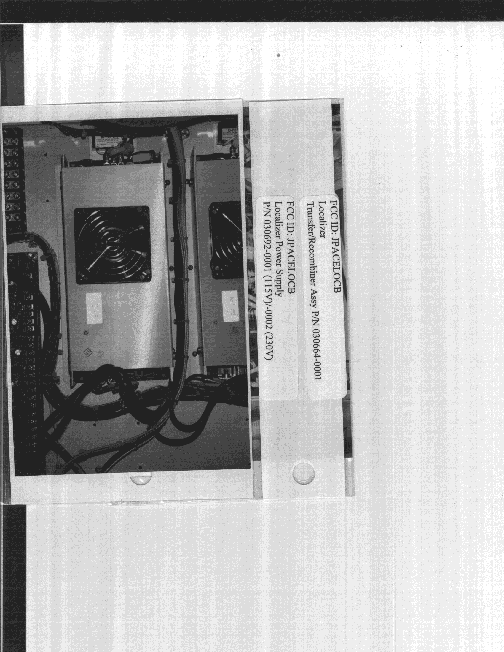
JPACELOCB
Dec 20, 1998Localizer
Equipment Class
TNB - Licensed Non-Broadcast Station TransmitterJPACEGSA
May 02, 1993TNB - Licensed Non-Broadcast Station Transmitter
Equipment Class
TNB - Licensed Non-Broadcast Station Transmitter