JPAMKR2Aviation Services Marker Beacon Transmitter
Indra Air Traffic Inc.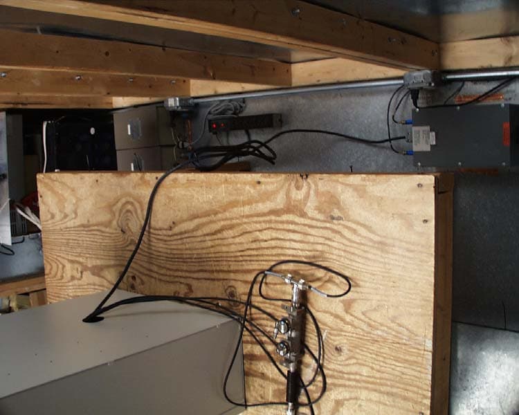
Click to zoom
Application Details
- Equipment Class
- TNB - Licensed Non-Broadcast Station Transmitter
- Date of Grant
- Oct 17, 2006
- Application Purpose
- Original Equipment
- Date of Application
- Oct 16, 2006
- Equipment Note
- Aviation Services Marker Beacon Transmitter
- Frequency Range
- 74.99600000 - 75.00400000
- Company
- Indra Air Traffic Inc.
- Country
- United States
Documents & Files
Document Text
Text extracted from the exhibit documents filed with the FCC. Open a document above to read the original.
Users Manual
THIS DOCUMENT CONTAINS PROPRIETARY INFORMATION AND SUCH INFORMATION MAY NOT BE DISCLOSED TO OTHERS FOR ANY PURPOSES WITHOUT WRITTEN PERMISSION FROM SELEX Sistemi Integrati Inc. Copyright © 2006, SELEX Sistemi Integrati Inc. Operations and Maintenance Manual Model 2130 Marker Beacon 572130-0001 Rev A April, 2005 SELEX Sistemi Integrati Inc. 11300 West 89th Street Overland Park, KS U.S.A. 66214 THIS SHEET INTENTIONALLY BLANK SAFETY SUMMARY The following are general safety precautions that are unrelated to specific procedures and therefore do not appear elsewhere in this publication. These are recommended precautions that personnel should understand and apply during through the many phases of operation and maintenance. ELECTROSTATIC SENSITIVE DEVICES PRECAUTIONS Since most modules used in all models of equipment have Electrostatic Discharge (ESD) sensitive devices included in them, all modules should be considered sensitive to electrostatic discharge. Handling in the field shall be the same as in the factory. Each system is shipped with a wrist strap that must be worn while maintaining the equipment. The wrist strap shall be fastened to the equipment chassis either in the designated plug-in or attached to the equipment chassis with the alligator clip. The wrist strap must be used before any modules are removed from the equipment and at all times while handling the modules until they are placed in a protective environment such as an anti-static bag. Modules or boards must not be placed on any non-conducting surface such as wooden work benches, painted metal work benches, plastics, or technical manuals. Any work surface to be used must have a conducting mat placed on it and attached to earth ground. The mat and additional wrist straps can be obtained from SELEX Sistemi Integrati Inc. KEEP AWAY FROM LIVE CIRCUITS Operating personnel must at all times observe all safety regulations. Under no circumstances should any person remove any protective covers that expose lethal voltages. Do not replace components or make adjustments inside the equipment with primary power supply turned on. Under certain conditions, dangerous potentials may exist when the power is in the off position, due to charges retained by capacitors. To avoid casualties, always remove power and allow time for the capacitors to discharge before touching it. DO NOT SERVICE OR ADJUST ALONE Under no circumstances should any person reach into or enter the enclosure for the purpose of servicing or adjusting the equipment except in the presence of someone who is capable of rendering aid. RESUSCITATION Personnel working with or near high voltages should be familiar with modern methods of resuscitation. THIS SHEET INTENTIONALLY BLANK SELEX Sistemi Integrati Inc. This equipment is supplied by SELEX Sistemi Integrati Inc. For replacement parts and repair service, contact SELEX Sistemi Integrati Inc. using the contact information provided below. HOW TO ORDER REPLACEMENT PARTS When ordering replacement parts, you should contact SELEX Sistemi Integrati Inc. by fax, phone or email. Please address the following items (as applicable) in your correspondence to enable us to provide the best possible service. 1. SELEX Sistemi Integrati Inc. model number, type and serial number of equipment. 2. Unit sub-assembly number (where applicable). 3. Item or reference symbol number from parts list or schematic. 4. SELEX Sistemi Integrati Inc. part number and description. 5. Manufacturer's code, name and part number (where applicable). 6. Quantity of each replacement part required. HOW TO REQUEST REPAIR SERVICE In order to ensure prompt attention, parts returned for repair should have the following: 1. RMA number (Return Material Authorization number), assigned prior to return when requesting repair service. 2. Unit part number 3. Site location 4. System information 5. Ship-to address for return 6. Contact name and number 7. Date and time of request CONTACT INFORMATION SELEX Sistemi Integrati Inc. 11300 W 89th Street Overland Park KS, 66214, USA Main Switchboard: (913) 495-2600 Main Fax: (913) 492-0870 Toll free: (800) 331-2744 CSM Direct Phone: (913) 495-2625 CSM E-mail: [email protected] World Wide Web URL: www.selex-si-us.com THIS SHEET INTENTIONALLY BLANK MANUFACTURER’S WARRANTY SELEX Sistemi Integrati Inc. The following warranty is applicable in all cases, except where modified or superseded by specific contract terms. Contact SELEX Sistemi Integrati Inc. if clarification is required. A. The Manufacturer warrants to the original Purchaser, subject to the limitations and exclusions stated below, that mechanical and electrical parts of products which it manufactures, (the “Products” will be free of defects in materials and workmanship for a period of (I) one (1) year from the date of installation or (ii) 18 months from the date of shipment, whichever first occurs (the “Warranty Period”). B. If the Customer believes a Product is defective, notice thereof shall be provided to the Manufacturer’s Customer Service Department at the address provided on the cover page and (if applicable) to the selling distributor. A defect in material and workmanship covered by this warranty shall be deemed to have occurred only if, and as of the time when, the Manufacturer is notified in writing by the Customer, within the Warranty Period, that the Product has become defective, and the Manufacturer’s personnel verify that the said Product, in fact, does not comply with the warranty provided hereunder and it is determined that: (i) The Products, during the entire Warranty Period, have been operated within normal service conditions, recommended by the Manufacturer and recognized in the industry, and (ii) The Products have been installed and adjusted according to the Manufacturer’s procedures as stated in the Instruction Manual or other instructions supplied in writing by the Manufacturer. C. Failures caused by lightning or other acts of God, or power surges, are not considere…
Text truncated - open the document above for the full version.
Cover Letter(s)
September 29, 2006 Timco Engineering Inc. 849 NW State Road 45 Newberry, FL 32669 Office of Engineering and Technology Federal Communications Commission Columbia, MD 21046 Applicant: SELEX SISTEMI INTEGRATI INC. 11300 West 89th Street Overland Park, KS 66214 Re: Confidentiality for submittal information regarding FCC ID number JPAMKR2 PRODUCT: Aviation Services Transmitter (Marker Beacon). Dear Sirs: Short-term Pursuant to DA 04-1705 of the Commission’s pubic notice, we request short-term confidential treatment for the following information until 45 days after the Grant Date of Equipment Authorization in order to ensure sensitive business information remains confidential until the actual marketing of the device: External Photos, file Selex 2130 JPAMKR2 External Photos.pdf Internal Photos, file Selex 2130 JPAMKR2 Internal Photos.pdf Test Setup Photos, file Selex 2130 JPAMKR2 Test Setup Photos.pdf User Manual, file 572130-0001A Manual.pdf Permanent SELEX SISTEMI INTEGRATI INC. requests that the material in the Parts List, Schematics, block diagram, and Operational Description be withheld from public disclosure in accordance with Section 0.459 of the Commissions Rules, 47 C.F.R. 0.459, following grant of the application. In support of this request, SELEX SISTEMI INTEGRATI INC. submits the following: Parts List, file PL012141-0001 parts.pdf Parts List, file PL012141-1001 parts.pdf Schematic, file 012141-9001 schematic.pdf Schematic, file 012130-9001 schematic.pdf Block Diagram, file Selex 2130 JPAMKR2 Block Diagram.pdf Operational Description, file Selex 2130 JPAMKR2 Operation Theory.pdf 1. Identification of the specific information for which confidential treatment is sought: The materials set fourth in the Operational Description, Parts List, block diagram, and Schematics, which are segregated from the non-confidential exhibits of the application, are those for which confidentiality is sought. ROGERS LABS, INC. 4405 West 259 th Terrace Louisburg, KS 66053 2. Identification of the Commission proceeding in which the information was submitted or a description of the circumstances giving rise to the submission: The proceeding is that involving the application for equipment authorization (certification) under FCC ID No: JPAMKR2 3. Explanation of the degree to which the information is commercial or financial, or contains a trade secret or is privileged: This material includes a detailed theory of operation, circuit diagrams, (schematic diagrams) and detail Parts List. As such, this material is treated as highly confidential business information. 4. Explanation of the degree to which the information concerns a service that is subject to competition: The material for which confidentiality is sought is employed in the design and manufacture of this transmitting equipment that is offered on a highly competitive basis. Customers for this equipment have a variety of competing sources. 5. Explanation of how disclosure of the information could result in substantial competitive harm: Disclosure would, in effect, give away the fruits of the labors of SELEX SISTEMI INTEGRATI INC.’s engineering personnel, who have designed the equipment and the manufacturing process. Disclosure would also offer competitors additional unwarranted insight into the state of the product development, thereby allowing competitors an advantage, not available to SELEX SISTEMI INTEGRATI INC. 6. Identification of any measures taken by the submitting party to prevent unauthorized disclosure: The information for which confidential treatment is sought is kept confidential by SELEX SISTEMI INTEGRATI INC. and not made available to third parties except pursuant to non-disclosure agreements. 7. Identification of whether the information is available to the public and the extent of any previous disclosure of the information to third parties: To the knowledge of those preparing this application, the information has not been disclosed publicly heretofore. While the general theory of operation of this equipment has been the subject of numerous disclosures in industry and standards groups as well as in rule making proceedings of the FCC, the protection sought is narrowly drawn and pertains to certain specific implementations of this radio technology. 8. Justification of the period during which the submitting party asserts that the material should not be available for public disclosure: This material should not be disclosed for at least 25 years. While improvements in design are made relatively frequently, disclosure of the design information would lead to insights into both design and manufacturing techniques that could have an adverse competitive effect for many years to come. This equipment is designed for commercial, industrial, and governmental applications. As such, unlike most consumer equipment, this equipment could be used for more than a decade in some cases. As such, it is important that the design not be made available to unauthorized persons who might attempt to use knowledge of the design to compromise the applications for which the equipment will be employed. Should you require any further information, please contact the undersigned. Thank you for your consideration in this matter. Sincerely, Scot Rogers
Cover Letter(s)
October 11, 2006 Timco Engineering Inc. 849 NW State Road 45 Newberry, FL 32669 Applicant: SELEX SISTEMI INTEGRATI INC. 11300 West 89th Street Overland Park, KS 66214 Re: Response to Request for Additional information Equipment: FCC ID: JPAMKR2 Gentlemen: A portion of the correspondence requesting additional information is shown below for reference. The response to this request is addressed below for your consideration. Request 1. Please confirm that this device is a Radio beacon station. A station in the radio navigation service the emissions of which are intended to enable a mobile station to determine its bearing or direction in relation to the radio beacon station. 2. Form 731: Please confirm that the application is made for 74.996-75.004MHz. 3. User’s manual – RF exposure compliance: Users and installers must be provided with appropriate antenna installation instructions and transmitter operating conditions, including antenna co-location requirements of §1.1307(b)(3), for satisfying RF exposure compliance. Please include such a statement “The antenna(s) used for this transmitter must be fixed-mounted on outdoor permanent structures with a separation distance of at least 20cm from all persons during normal operation. The peak conducted output power at each antenna terminal must not exceed 3.2W and the peak radiated output power must not exceed 25.1W EIRP. 4. FAA – par 87.147(d)(2) and (d)(3): TCBs are required to have the reply from the FAA before issuing a grant of equipment authorization. Please submit the response letter from the FAA when available. Response Below please find relevant photographs per your request demonstrating spacing between the back of the device and antenna, and the back of the clip and antenna. 1. The Equipment design, installation, and use allow a mobile station to determine its bearing or direction in relation to the radio beacon station EUT (JPAMKR2). 2. The unit operates on the frequencies discussed and reported in the test report and documentation. If the current policy to issue grant of certification for 75 MHz (allowing operation in a +/- 1 MHz band about 75 MHz), issuance of a grant of certification displaying 75 MHz frequency of operation would be acceptable. 3. The equipment and antenna arrangement are located in a controlled access area (airport) limiting the possibility RF exposure. Appropriate information will be added to the user/installation manual for compliance. Please refer to file “radiation hazard informaiton.pdf” which will be included in the appropriate section of the manual. 4. The FAA confirmation letter has been attached. Please refer to file “Selex_2130_marker- beacon.pdf” for the FAA letter of acceptance. Please review this information and continue processing the application for grant of certification. Should you require any further information, please contact the undersigned. Thank you for your consideration in this matter. Sincerely, Scot Rogers Rogers Labs, Inc. Enclosures
External Photos
ROGERS LABS, INC. Selex Sistemi Integrati Inc. 4405 W. 259th Terrace Model: 2130 FCCID#: JPAMKR2 Louisburg, KS 66053 Test #: 060822 SN: EDM1511 Phone/Fax: (913) 837-3214 Test to: FCC Parts 2 and 87 Page 1 of 3 Selex 2130 JPAMKR2 External Photos 9/14/2006 EUT Enclosure front EUT Enclosure rear ROGERS LABS, INC. Selex Sistemi Integrati Inc. 4405 W. 259th Terrace Model: 2130 FCCID#: JPAMKR2 Louisburg, KS 66053 Test #: 060822 SN: EDM1511 Phone/Fax: (913) 837-3214 Test to: FCC Parts 2 and 87 Page 2 of 3 Selex 2130 JPAMKR2 External Photos 9/14/2006 EUT Top EUT Bottom ROGERS LABS, INC. Selex Sistemi Integrati Inc. 4405 W. 259th Terrace Model: 2130 FCCID#: JPAMKR2 Louisburg, KS 66053 Test #: 060822 SN: EDM1511 Phone/Fax: (913) 837-3214 Test to: FCC Parts 2 and 87 Page 3 of 3 Selex 2130 JPAMKR2 External Photos 9/14/2006 EUT Inside Enclosure Note: EUT Mounted to left side of enclosure
ID Label/Location Info
ROGERS LABS, INC. Selex Sistemi Integrati Inc. 4405 W. 259th Terrace Model: 2130 FCCID#: JPAMKR2 Louisburg, KS 66053 Test #: 060822 SN: EDM1511 Phone/Fax: (913) 837-3214 Test to: FCC Parts 2 and 87 Page 1 of 2 Selex 2130 JPAMKR2 ID Label 9/14/2006 EUT FCC ID Label locations ROGERS LABS, INC. Selex Sistemi Integrati Inc. 4405 W. 259th Terrace Model: 2130 FCCID#: JPAMKR2 Louisburg, KS 66053 Test #: 060822 SN: EDM1511 Phone/Fax: (913) 837-3214 Test to: FCC Parts 2 and 87 Page 2 of 2 Selex 2130 JPAMKR2 ID Label 9/14/2006
Internal Photos
ROGERS LABS, INC. Selex Sistemi Integrati Inc. 4405 W. 259th Terrace Model: 2130 FCCID#: JPAMKR2 Louisburg, KS 66053 Test #: 060822 SN: EDM1511 Phone/Fax: (913) 837-3214 Test to: FCC Parts 2 and 87 Page 1 of 2 Selex 2130 JPAMKR2 Internal Photos 9/14/2006 Photographs inside Enclosure of EUT ROGERS LABS, INC. Selex Sistemi Integrati Inc. 4405 W. 259th Terrace Model: 2130 FCCID#: JPAMKR2 Louisburg, KS 66053 Test #: 060822 SN: EDM1511 Phone/Fax: (913) 837-3214 Test to: FCC Parts 2 and 87 Page 2 of 2 Selex 2130 JPAMKR2 Internal Photos 9/14/2006 Transmitter PCB
Parts List/Tune Up Info
ROGERS LABS, INC. Selex Sistemi Integrati Inc. 4405 W. 259th Terrace Model: 2130 FCCID#: JPAMKR2 Louisburg, KS 66053 Test #: 060822 SN: EDM1511 Phone/Fax: (913) 837-3214 Test to: FCC Parts 2 and 87 Page 1 of 1 Selex 2130 JPAMKR2 Tune 9/14/2006 Refer to section 2.3.1.2 of owners/installation manual for detailed Circuit theory and tuning.
RF Exposure Info
SAFETY SUMMARY The following are general safety precautions that are unrelated to specific procedures and therefore do not appear elsewhere in this publication. These are recommended precautions that personnel should understand and apply during through the many phases of operation and maintenance. ELECTROSTATIC SENSITIVE DEVICES PRECAUTIONS Since most modules used in all models of equipment have Electrostatic Discharge (ESD) sensitive devices included in them, all modules should be considered sensitive to electrostatic discharge. Handling in the field shall be the same as in the factory. Each system is shipped with a wrist strap that must be worn while maintaining the equipment. The wrist strap shall be fastened to the equipment chassis either in the designated plug-in or attached to the equipment chassis with the alligator clip. The wrist strap must be used before any modules are removed from the equipment and at all times while handling the modules until they are placed in a protective environment such as an anti-static bag. Modules or boards must not be placed on any non-conducting surface such as wooden work benches, painted metal work benches, plastics, or technical manuals. Any work surface to be used must have a conducting mat placed on it and attached to earth ground. The mat and additional wrist straps can be obtained from SELEX Sistemi Integrati Inc. KEEP AWAY FROM LIVE CIRCUITS Operating personnel must at all times observe all safety regulations. Under no circumstances should any person remove any protective covers that expose lethal voltages. Do not replace components or make adjustments inside the equipment with primary power supply turned on. Under certain conditions, dangerous potentials may exist when the power is in the off position, due to charges retained by capacitors. To avoid casualties, always remove power and allow time for the capacitors to discharge before touching it. DO NOT SERVICE OR ADJUST ALONE Under no circumstances should any person reach into or enter the enclosure for the purpose of servicing or adjusting the equipment except in the presence of someone who is capable of rendering aid. RESUSCITATION Personnel working with or near high voltages should be familiar with modern methods of resuscitation. RADIATION EXPOSURE The antenna(s) used for this transmitter must be fixed-mounted on outdoor permanent structures with a separation distance of at least 20cm from all persons during normal operation. The peak conducted output power at each antenna terminal must not exceed 3.2W and the peak radiated output power must not exceed 25.1W EIRP. THIS SHEET INTENTIONALLY BLANK MODEL 2130 MARKER BEACON Rev. B October, 2006 9-1 This document contains proprietary information and such information may not be disclosed to others for any purposes without written permission from SELEX Sistemi Integrati Inc. 9. INSTALLATION, INTEGRATION AND CHECKOUT The antenna(s) used for this transmitter must be fixed-mounted on outdoor permanent structures with a separation distance of at least 20cm from all persons during normal operation. The peak conducted output power at each antenna terminal must not exceed 3.2W and the peak radiated output power must not exceed 25.1W EIRP. 9.1 Introduction This section contains the information required to install the equipment, inspect the installation, perform startup and preliminary testing procedures, and perform an installation verification test. 9.2 Site Information The Marker Beacons are located along the extended runway centerline to provide a rough indication of an aircraft's distance from the runway threshold, and to indicate significant points along an instrument approach path. An Outer Marker is typically located 4 nautical miles from the runway threshold; this location normally coincides with the point on the Marker Beacon approach at which the glide slope altitude equals the intercept altitude. A Middle Marker is typically located 3500 feet from the runway threshold; this location normally coincides with the point on the glide path at which the decision height (DH) is located for Category I operations--200 feet above the touchdown zone elevation. A typical Marker Beacon site plan is illustrated in Figure 9-1. This illustration shows the shelter and tower foundation locations, trenching details, and site preparation requirements. The terrain around the Marker Beacon site is to be graded to the specifications of FAA Order 6750.16B, Siting Criteria for Instrument Landing Systems, or as determined by the siting engineer. 9.3 Unpacking and Repacking Packing cases are to be handled and opened with care to avoid damage to electronics components. Be certain all fasteners, supports, and tie-downs have been removed before attempting to remove the units. Inspect all items for ship- ping damage and check against the packing slip to ensure complete shipment. Check the packing slip against Table 1-2. 9.4 Input Requirement Summary Refer to Table 1-1 for input power requirements. 9.5 Installation Procedures 9.5.1 Installation Test Equipment Refer to Table 1-3 for a list of test equipment required for installation. MODEL 2130 MARKER BEACON 9-2 Rev. B October, 2006 This document contains proprietary information and such information may not be disclosed to others for any purposes without written permission from SELEX Sistemi Integrati Inc. Figure 9-1 Typical Marker Beacon Site Details
RF Exposure Info
ROGERS LABS, INC. Selex Sistemi Integrati Inc. 4405 W. 259th Terrace Model: 2130 FCCID#: JPAMKR2 Louisburg, KS 66053 Test #: 060822 SN: EDM1511 Phone/Fax: (913) 837-3214 Test to: FCC Parts 2 and 87 Page 1 of 1 Selex 2130 JPAMKR2 MPE Claculation 9/14/2006 MPE CalculatorMPE uses EIRP for calculation. EIRP is based on TX power added to the antenna gain in dBi. dBi = dB gain compared to an isotropic radiator. S = power density in mW/cm^2 Antenna Gain (dBi)9 Output PowerdBd + 2.17 = dBidBi to dBd3 Tx Frequency (MHz)75Average (Watts)3.0000Antenna Gain (dBd)6 Cable Loss (dB)0.0(dBm)34.77Antenna minus cable (dBi)9.00 Calculated ERP (mw) 11943.215EIRP = Po(dBM) + Gain (dB) Calculated EIRP (mw) 23829.847Radiated (EIRP) dBm43.771 ERP = EIRP - 2.17 dB Occupational LimitRadiated (ERP) dBm40.771 0.25000 mW/cm 2 General Public Limit 0.05000 mW/cm 2 Frequency (MHz)Occupational LimitPublic Limit 300-1,500f/300f/1500 1,500-10,00051 Frequency (MHz) Occupational Limit @ Tx Freq (mW/cm^2) Public Limit @ Tx Freq (mW/cm^2) 300-1,5000.250.05 1,500-10,00051 EIRPDistanceDistanceSDistance milliwattscminchesmW/c m 2 Feet 23829.847350.00137.800.0154811.48293963 23829.847300.00118.110.021079.842519685 23829.847275.00108.270.025089.022309711 23829.847250.0098.430.030348.202099738 23829.847225.0088.580.037467.381889764 23829.847200.0078.740.047416.56167979 23829.847175.0068.900.061925.741469816 23829.847150.0059.060.084284.921259843 23829.847125.0049.210.121364.101049869 23829.847100.0039.370.189633.280839895 23829.84790.0035.430.234112.952755906 23829.84780.0031.500.296302.624671916 23829.84770.0027.560.387002.296587927 23829.84760.0023.620.526761.968503937 23829.84750.0019.690.758531.640419948 23829.84740.0015.751.185201.312335958 23829.84730.0011.812.107020.984251969 23829.84725.009.843.034110.820209974 23829.84720.007.874.740800.656167979 23829.84715.005.918.428080.492125984 23829.84714.005.519.675100.459317585 23829.84713.005.1211.220820.426509186 23829.84712.004.7213.168880.393700787 23829.84711.004.3315.672060.360892388 23829.84710.003.9418.963190.32808399 23829.8479.003.5423.411350.295275591 23829.8478.003.1529.629980.262467192 23829.8477.002.7638.700390.229658793 23829.8476.002.3652.675530.196850394 23829.8475.001.9775.852760.164041995 23829.8471.600.63740.749600.052493438 Frequency (MHz) Occupational Limit minimum Distance (inches) Public Limit minimum distance (inches) 300-1,5000.633.20 1,500-10,000N/AN/A FCC radio frequency radiation exposure limits per 1.1310 FCC radio frequency radiation exposure limits per 1.1310 Power density (S) EIRP ------- = mW/cm^2 4 π r^2 r (cm) EIRP (mW)
Test Report
APPLICATION SUBMITTAL FOR FCC GRANT OF CERTIFICATION Per CFR47 Part 87 FOR MODEL: 2130 74.996-75.004 MHz MARKER BEACON TRANSMITTER FCC ID: JPAMKR2 FOR Selex Sistemi Integrati Inc. 11300 West 89th Street Overland Park, KS 66214 Test Report Number 060822 NVLAP Accredited Laboratory NVLAP Lab Code: 200087-0 ROGERS LABS, INC. Selex Sistemi Integrati Inc. 4405 West 259 th Terrace MODEL: 2130 SN: EDM1511 Louisburg, KS 66053 Test #: 060822 FCC ID#: JPAMKR2 Phone/Fax: (913) 837-3214 Test to: FCC Parts 2, 15 and 87 Page 2 of 20 Selex 2130 Mrkr Test Report.doc 9/14/2006 TEST REPORT For APPLICATION of CERTIFICATION For SELEX SISTEMI INTEGRATI INC. 11300 West 89th Street OVERLAND PARK, KS 66214 Phone: (913) 495-2667 Kurt Rieke Product Manager MARKER BEACON TRANSMITTER Model: 2130 Frequency Range: 74.996-75.004 MHz FCC ID: JPAMKR2 Test Date: August 22, 2006 Certifying Engineer: Scot D. Rogers ROGERS LABS, INC. 4405 West 259th Terrace Louisburg, KS 66053 Phone: (913) 837-3214 FAX: (913) 837-3214 This report shall not be reproduced except in full, without the written approval of the laboratory. This report must not be used by the client to claim product endorsement by NVLAP or any agency of the U.S. Government. Rogers Labs, Inc. 4405 West 259 th Terrace Louisburg, KS 66053 Phone / Fax (913) 837-3214 NVLAP Accredited Laboratory NVLAP Lab Code: 200087-0 ROGERS LABS, INC. Selex Sistemi Integrati Inc. 4405 West 259 th Terrace MODEL: 2130 SN: EDM1511 Louisburg, KS 66053 Test #: 060822 FCC ID#: JPAMKR2 Phone/Fax: (913) 837-3214 Test to: FCC Parts 2, 15 and 87 Page 3 of 20 Selex 2130 Mrkr Test Report.doc 9/14/2006 TABLE OF CONTENTS TABLE OF CONTENTS 3 FORWARD 4 LIST OF TEST EQUIPMENT 4 2.1033(C) APPLICATION FOR CERTIFICATION 5 2.1046 RF POWER OUTPUT 6 Measurements Required 6 Test Arrangement 6 Results 7 2.1047 MODULATION CHARACTERISTICS 8 Measurements Required 8 Test Arrangement 8 Results 8 2.1049 OCCUPIED BANDWIDTH 9 Measurements Required 9 Test Arrangement 9 Results 9 2.1051 SPURIOUS EMISSIONS AT ANTENNA TERMINALS 10 Measurements Required 10 Test Arrangement 10 Results 11 2.1053 FIELD STRENGTH OF SPURIOUS RADIATION 12 Measurements Required 12 Test Arrangement 12 Results 14 2.1055 FREQUENCY STABILITY 14 Measurements Required 14 Test Arrangement 15 Results 16 APPENDIX 17 NVLAP Accredited Laboratory NVLAP Lab Code: 200087-0 ROGERS LABS, INC. Selex Sistemi Integrati Inc. 4405 West 259 th Terrace MODEL: 2130 SN: EDM1511 Louisburg, KS 66053 Test #: 060822 FCC ID#: JPAMKR2 Phone/Fax: (913) 837-3214 Test to: FCC Parts 2, 15 and 87 Page 4 of 20 Selex 2130 Mrkr Test Report.doc 9/14/2006 FORWARD In accordance with the Federal Communications Commission (FCC) Code of Federal Regulations (CFR), dated October 1, 2005, Part 2 Subpart J, Paragraphs 2.907, 2.911, 2.913, 2.915, 2.925, 2.926, 2.1031 through 2.1057, and Part 87, Subchapter D, Paragraphs 87.131 through 87.147, and applicable paragraphs of Part 15, the following information is submitted. List of Test Equipment A Hewlett Packard 8591EM and or 8562A Spectrum Analyzer was used as the measuring device for the emissions testing. The analyzer settings used are described in the following table. Refer to the Appendix for a complete list of Test Equipment. HP 8591EM SPECTRUM ANALYZER SETTINGS CONDUCTED EMISSIONS: RBW AVG. BW DETECTOR FUNCTION 9 kHz 30 kHz Peak/Quasi Peak RADIATED EMISSIONS (30 – 1000 MHz) RBW AVG. BW DETECTOR FUNCTION 120 kHz 300 kHz Peak/Quasi Peak HP 8562A SPECTRUM ANALYZER SETTINGS RADIATED EMISSIONS (1 – 40 GHz) RBW AVG. BW DETECTOR FUNCTION 1 MHz 1 MHz Peak/Average ANTENNA CONDUCTED EMISSIONS RBW AVG. BW DETECTOR FUNCTION 300 Hz -120 kHz 100 kHz Peak NVLAP Accredited Laboratory NVLAP Lab Code: 200087-0 ROGERS LABS, INC. Selex Sistemi Integrati Inc. 4405 West 259 th Terrace MODEL: 2130 SN: EDM1511 Louisburg, KS 66053 Test #: 060822 FCC ID#: JPAMKR2 Phone/Fax: (913) 837-3214 Test to: FCC Parts 2, 15 and 87 Page 5 of 20 Selex 2130 Mrkr Test Report.doc 9/14/2006 2.1033(c) Application for Certification (1) Manufacturer: SELEX SISTEMI INTEGRATI INC. 11300 West 89th Street OVERLAND PARK, KS 66214 (2) Identification: FCC I.D.: JPAMKR2 (3) Instruction Book: Refer to exhibit for Draft Instruction Manual. (4) Emission Type: Emissions designator 6k00A2D. Double-sideband amplitude modulated single channel, data transmission. (5) Frequency Range: 74.996-75.004 MHz (6) Operating Power Level: 3 - 0.050 Watts (Software adjustable at installation) delivered from the EUT. (7) Maximum P o : 3 Watts delivered from the EUT. Maximum power output varies as approved by Federal Aviation Administration. (8) Power into final amplifying circuitry: Final driver and amplifier 5.4 volts @ 1.43 amps, 7.7 watts. (9) Tune Up Procedure for Output Power: Refer to Exhibit for Transmitter Alignment Procedure. (10) Circuit Diagrams; description of circuits, frequency stability, spurious suppression, and power and modulation limiting: Refer to Exhibit for Circuit Diagrams. Refer to Exhibit for Theory of Operation. (11) Photograph or drawing of the Identification Plate: Refer to Exhibit for Photograph or Drawing. (12) Drawings of Construction and Layout: Refer to Exhibit for Drawings/pictures of Components Layout and Chassis Drawings. (13) Detail Description of Digital Modulation: Not applicable. NVLAP Accredited Laboratory NVLAP Lab Code: 200087-0 ROGERS LABS, INC. Selex Sistemi Integrati Inc. 4405 West 259 th Terrace MODEL: 2130 …
Text truncated - open the document above for the full version.
Contact Information
Applicant
Luke Jones(VP of Quality)
Test Firm
Rogers Labs, Inc.Scot Rogers
Technical Specifications
| # | Rule Parts | Frequency Range | Power Output | Emission | Tolerance |
|---|---|---|---|---|---|
| 1 | 87 | 74.996 MHz - 75.004 MHz | 3 W | 6K00A2D | 2.0000000000 ppm |
Other Applications from Indra Air Traffic Inc.
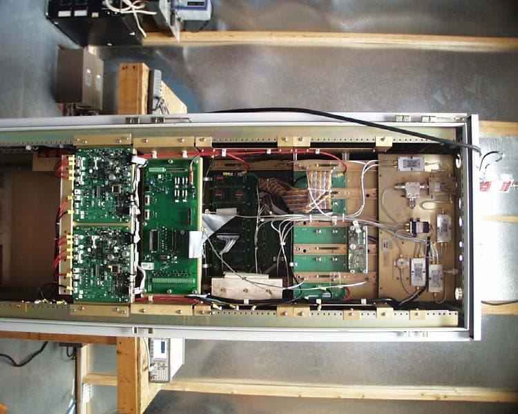
JPADMEL2
Oct 17, 2006Aviation Services DME Transmitter
Equipment Class
TNB - Licensed Non-Broadcast Station Transmitter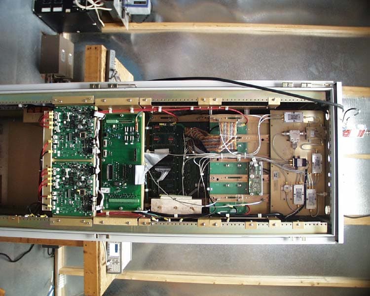
JPADMEH2
Oct 16, 2006AVIATION SERVICES DME TRANSMITTER
Equipment Class
TNB - Licensed Non-Broadcast Station Transmitter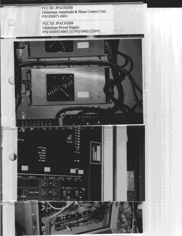
JPACEGSB
Dec 20, 1998Glideslope
Equipment Class
TNB - Licensed Non-Broadcast Station Transmitter
JPACELOCB
Dec 20, 1998Localizer
Equipment Class
TNB - Licensed Non-Broadcast Station TransmitterJPACEGSA
May 02, 1993TNB - Licensed Non-Broadcast Station Transmitter
Equipment Class
TNB - Licensed Non-Broadcast Station Transmitter