JWFTS4000GLRadio Modem
Teledesign Systems Inc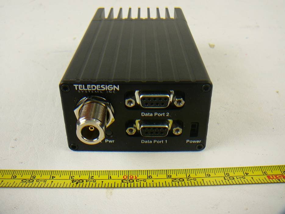
Click to zoom
Application Details
- Equipment Class
- TNB - Licensed Non-Broadcast Station Transmitter
- Date of Grant
- Oct 28, 2012
- Application Purpose
- Original Equipment
- Date of Application
- Oct 28, 2012
- Equipment Note
- Radio Modem
- Frequency Range
- 136.00000000 - 162.00000000
- Company
- Teledesign Systems Inc
- Country
- United States
Documents & Files
Document Text
Text extracted from the exhibit documents filed with the FCC. Open a document above to read the original.
Users Manual
TS4000 Radio Modem User’s Manual 1729 South Main Street Milpitas, CA 95035 (408) 941-1808 (800) 663-3674 (408) 941-1818 Fax www.teledesignsystems.com [email protected] [email protected] This document is copyrighted by Teledesign Systems Inc. with all rights reserved. No part of this document may be reproduced in any form without the prior written consent of Teledesign Systems Inc. Copyright Copyright 2012 by Teledesign Systems Inc. All rights reserved. This manual has been thoroughly reviewed for accuracy, and every effort has been made to ensure that the information is accurate and complete. However, different versions of this product have different features and capabilities, and this manual reflects only one of those versions. Therefore, Teledesign Systems Inc. assumes no responsibility for errors, omissions or defects in this material, and shall not be liable for any damages resulting from their use. Disclaimer The information in this document is subject to change without notice. TELEDESIGN SYSTEMS INC. MAKES NO WARRANTY OF ANY KIND WITH RESPECT TO THIS DOCUMENT AND SOFTWARE, EITHER EXPRESSED OR IMPLIED, INCLUDING WITHOUT LIMITATION ANY IMPLIED WARRANTIES OF MERCHANTABILITY OR FITNESS FOR A PARTICULAR PURPOSE. Emissions FCC The TS4000 complies with Part 15 of the FCC Rules (Code of Federal Regulations 47CFR Part 15). Operation is subject to the following two conditions: (1) This device does not cause harmful interference, and (2) this device must accept any interference received, including interference that may cause undesired operation. Part 15 The TS4000 has been type accepted for operation by the FCC in accordance with Part 90 of the FCC rules (47CFR Part 90). See the label on the unit for the specific FCC ID and any other certification designations. Part 90 The TS4000 has been type accepted for operation by the FCC in accordance with Part 95 of the FCC rules (47CFR Part 95). See the label on the unit for the specific FCC ID and any other certification designations. Part 95 Industry Canada This Class B digital apparatus meets all requirements of the Canadian Interference-Causing Equipment Regulations. ICES-003 The TS4000 has been certified for operation by Industry Canada in accordance with RSS-119 of the Industry Canada rules. See the label on the unit for the specific Industry Canada certification number and any other certification designations. RSS-119 Changes or modifications not expressly approved by Teledesign Systems Inc. could void the user’s authority to operate this equipment. Notice Shielded cable must be used with this equipment in order to ensure that it meets the emissions limits for which it was designed. It is the responsibility of the user to obtain and use good quality shielded cables with this device. In order to ensure the safe operation of this radio equipment, the following practices should be observed. Safety Warning DO NOT operate radio equipment near electrical blasting caps or in an explosive atmosphere. DO NOT operate any radio transmitter unless all RF connectors are secure and any open connectors are properly terminated. DO NOT allow the antenna to come close to, or touch, the eyes, face, or any exposed body parts while the radio is transmitting. In order to ensure the safe operation of this radio equipment, the minimum distance that a person should be from the attached antenna when this equipment is transmitting is 6 ft. (180 cm). This is based on using the TS4000 at a power of 5 watts with a 10dBd (12.1dbi) gain antenna. RF Exposure TS4000 Radio Modem User’s Manual Emissions iii Table of Contents Emissions ......................................................................................................iii FCC.................................................................................................... iii Industry Canada................................................................................. iii Notice.......................................................................................................iii Safety Warning .......................................................................................iii RF Exposure ...........................................................................................iii Table of Contents..........................................................................................iv TS4000 Overview ...........................................................................................1 Introduction..............................................................................................1 Features....................................................................................................1 Connections.............................................................................................3 Serial Port ...........................................................................................3 Antenna Connector .............................................................................3 Power Connection...............................................................................3 Mounting ..................................................................................................4 Configuring the TS4000 ..........................................................................4 AirTest - Data Testing .............................................................................4 Upgrading the TS4000 Firmware ...........................................................4 AirScan.....................................................................................................4 Remote Diagnostics ................................................................................4 AirCalc - Range Estimation ....................................................................5 Status Lights............................................................................................6 Configuration Program..............................…
Text truncated - open the document above for the full version.
External Photos
Teledesign Systems, Inc. FCC ID: JWFTS4000GL Report Number: R1209046-90GL Page 35 of 39 FCC Part 90 Test Report 14 Exhibit C - EUT Photographs 14.1 EUT - Top View 14.2 EUT – Bottom View Teledesign Systems, Inc. FCC ID: JWFTS4000GL Report Number: R1209046-90GL Page 36 of 39 FCC Part 90 Test Report 14.3 EUT – Port View 14.4 EUT – Side View
ID Label/Location Info
Suggested Label Location on EUT FCC Label: The label shown shall be permanently affixed at a conspicuous location on the device and be readily visible to the user at the time purchase (Labeling requirements per 2.925) Label here
Internal Photos
Teledesign Systems, Inc. FCC ID: JWFTS4000GL Report Number: R1209046-90GL Page 37 of 39 FCC Part 90 Test Report 14.5 EUT – Modem PCB Top View 14.6 EUT – Modem PCB Bottom View Teledesign Systems, Inc. FCC ID: JWFTS4000GL Report Number: R1209046-90GL Page 38 of 39 FCC Part 90 Test Report 14.7 EUT – Radio PCB Top View 14.8 EUT – Radio PCB Bottom View Teledesign Systems, Inc. FCC ID: JWFTS4000GL Report Number: R1209046-90GL Page 39 of 39 FCC Part 90 Test Report 14.9 EUT – Radio PCB (Shielding off) Top View 14.10 EUT – Radio PCB (Shielding off) Bottom View --- END OF REPORT ---
Parts List/Tune Up Info
Type Acceptance Information for TS4000 Radio Modem with 3433 Transceiver Proposed FCC ID : JWFTS4000GL Teledesign Systems, Inc Confidential Information Page 1 of 1 TS4000 Tune-up Procedure Introduction Tuning up the modem board and radio board pair consists of setting the tuning adjustments on the radio transceiver and also setting the tuning adjustments of the modem board. The tuning adjustments of the TS4000 modem board and DM-3433 radio transceiver are electronically tuned. Tuning the modem board adjustments requires using the TS4000 tune-up software that interfaces to the modem board through the serial port. Radio Configuration Before the modem board and radio transceiver are tuned up together, the modem board is configured for the specifics of the radio transceiver that it is connected to. This configuration sets the following radio parameters: Maximum Radio Power - This limits the maximum power that the user can configure the radio modem for. Frequency Range - This sets the frequency range that the radio transceiver is designed to operate over. This limits the frequencies that the radio channels can be set for. Maximum Modulation Rate - This limits the modulation rate that the user can configure the modem for. As a result, this limits the bandwidth of the transmit signal that the radio modem produces. Transmit Power Tune-up The transmit power is controlled by a DAC on the radio board. This DAC is controlled by the modem board by passing data to the microcontroller on the radio board through the SPI port. Procedure: 1) Connect the radio modem to a service monitor set to measure power. 2) Start the TS4000 tune-up software and set it so that the radio modem transmits at the maximum power on the middle transmit frequency. 3) Adjust the power setting to the correct level with the tune-up software. 4) Set the tune-up software for a lower transmit power. Adjust the power appropriately with the tune-up software. 5) Repeat step 4 for all power levels (1.0W, 2.0W, 5.0W) and transmit frequencies (lowest, center and highest) defined by the tune-up software. 6) With the tune-up software, store the tune-up values into the modem board’s non-volatile memory. Transmit Modulation Level Tune-up The transmit modulation level is set controlled by the amplitude of the modulation signal sent to the radio board from the modem board. Procedure: 1) Connect the radio modem to a service monitor set to monitor frequency deviation. 2) Start the TS4000 tune-up software and set it for the center frequency. 3) Using the software, adjust the deviation to the appropriate value. 4) Repeat step 3 for all frequencies (low, middle and high) defined by the tune-up software. 5) With the tune-up software, store the tune-up values into the modem board’s non-volatile memory. Transmit Frequency Error Tune-up The center transmit frequency error is controlled by the DC level of the modulation signal sent to the radio board from the modem board. Procedure: 1) Connect the radio modem to a service monitor set to measure frequency. 2) Start the TS4000 tune-up software and set it so that the radio modem transmits at maximum power on the center transmit frequency. 3) Adjust the frequency control settings in the software so that the transmit frequency is correct. 4) Store the values in the modem board’s non-volatile memory.
RF Exposure Info
Teledesign Systems, Inc. FCC ID: JWFTS4000GL Report Number: R1209046-90GL Page 9 of 39 FCC Part 90 Test Report 4 FCC §2.1091 - RF Exposure Information 4.1 Applicable Standards FCC §2.1091, (a) Requirements of this section are a consequence of Commission responsibilities under the National Environmental Policy Act to evaluate the environmental significance of its actions. See subpart I of part 1 of this chapter, in particular §1.1307(b). According to §1.1310 and §2.1091 RF exposure is calculated. Frequency Range (MHz) Electric Field Strength (V/m) Magnetic Field Strength (A/m) Power Density (mW/cm 2 ) Averaging Time (minutes) (B) Limits for General Population/Uncontrolled Exposure 0.3-1.34 614 1.63 *(100) 30 1.34-30 842/f 2.19/f *(180/f 2 ) 30 30-300 27.5 0.073 0.2 30 300-1500 / / f/1500 30 1500-100,000 / / 1 30 f = frequency in MHz * = Plane-wave equivalent power density MPE Prediction Predication of MPE limit at a given distance, Equation from OET Bulletin 65, Edition 97-01 S = PG/4πR² Where: S = power density P = power input to antenna G = power gain of the antenna in the direction of interest relative to an isotropic radiator R = distance to the center of radiation of the antenna Conclusion The device complies with the MPE requirements by providing a safe separation distance of at least 6 ft. (180) cm between the antenna with maximum 10 dBd (12.1 dBi) gain, including any radiating structure, and any persons when normally operated. RF exposure has been specified in the user manual. Maximum rated peak output power at antenna input terminal (dBm): 36.99 Maximum peak output power at antenna input terminal (mW): 5000 Prediction distance (cm): 180 Prediction frequency (MHz): 140.985 Maximum Antenna Gain, typical (dBi): 12.1 Maximum Antenna Gain (numeric): 16.218 Power density of prediction frequency at 180 cm (mW/cm 2 ): 0.199 MPE limit for uncontrolled exposure at prediction frequency (mW/cm 2 ): 0.2
Test Report
Note: This test report is prepared for the customer shown above and for the device described herein. It may not be duplicated or used in part without prior written consent from Bay Area Compliance Laboratories Corp. This report must not be used by the customer to claim product certification, approval, or endorsement by A2LA* or any agency of the Federal Government. * This report may contain data that are not covered by the A2LA accreditation and are marked with an asterisk “*” (Rev.3) FCC PART 90 TEST AND MEASUREMENT REPORT For Teledesign Systems, Inc. 1729 South Main Street, Milpitas, CA 95035, USA FCC ID: JWFTS4000GL Model: TS4000-05G13 Report Type: Original Report Product Type: VHF Radio Modem Test Engineer: Lionel Lara Report Number: R1209046-90GL Report Date: 2012-10-29 Reviewed By: Victor Zhang RF/EMC Lead Bay Area Compliance Laboratories Corp. 1274 Anvilwood Avenue, Sunnyvale, CA 94089, USA Tel: (408) 732-9162 Fax: (408) 732 9164 Teledesign Systems, Inc. FCC ID: JWFTS4000GL Report Number: R1209046-90GL Page 2 of 39 FCC Part 90 Test Report TABLE OF CONTENTS 1. General Information.............................................................................................................................................5 1.1 PRODUCT DESCRIPTION FOR EQUIPMENT UNDER TEST (EUT) ........................................................................5 1.2 MECHANICAL DESCRIPTION............................................................................................................................5 1.3 OBJECTIVE......................................................................................................................................................5 1.4 RELATED SUBMITTAL(S)/GRANT(S)................................................................................................................5 1.5 TEST METHODOLOGY.....................................................................................................................................6 1.6 MEASUREMENT UNCERTAINTY.......................................................................................................................6 1.7 TEST FACILITY................................................................................................................................................6 2 System Test Configuration...................................................................................................................................7 2.1 JUSTIFICATION................................................................................................................................................7 2.2 EUT EXERCISE SOFTWARE.............................................................................................................................7 2.3 EQUIPMENT MODIFICATIONS..........................................................................................................................7 2.4 INTERNAL CONFIGURATION............................................................................................................................7 2.5 LOCAL SUPPORT EQUIPMENT..........................................................................................................................7 2.6 LOCAL SUPPORT EQUIPMENT POWER SUPPLY AND LINE FILTERS..................................................................7 2.7 EXTERNAL I/O CABLING LIST AND DETAILS..................................................................................................7 3 Summary of Test Results......................................................................................................................................8 4 FCC §2.1091 - RF Exposure Information...........................................................................................................9 4.1 APPLICABLE STANDARDS...............................................................................................................................9 5 FCC §2.1046 & §90.205 – RF Output Power....................................................................................................10 5.1 APPLICABLE STANDARD...............................................................................................................................10 5.2 TEST PROCEDURE.........................................................................................................................................10 5.3 TEST EQUIPMENT LIST AND DETAILS............................................................................................................10 5.4 TEST ENVIRONMENTAL CONDITIONS............................................................................................................11 5.5 TEST RESULTS..............................................................................................................................................11 6 FCC §2.1047 & §90.207 – Modulation Characteristic .....................................................................................13 6.1 APPLICABLE STANDARD...............................................................................................................................13 6.2 TEST RESULT................................................................................................................................................13 7 FCC §2.1049 & §90.210 – Occupied Bandwidth & Emission Mask ...............................................................14 7.1 APPLICABLE STANDARD...............................................................................................................................14 7.2 TEST PROCEDURE.........................................................................................................................................14 7.3 TEST EQUIPMENT LIST AND DETAILS............................................................................................................14 7.4 TEST ENVIRONMENTAL CONDITIONS.............................................................…
Text truncated - open the document above for the full version.
Test Setup Photos
Teledesign Systems, Inc. FCC ID: JWFTS4000GL Report Number: R1209046-90GL Page 33 of 39 FCC Part 90 Test Report 13 Exhibit B - Test Setup Photographs 13.1 Radiated Emission below 1 GHz – Front View 13.2 Radiated Emission below 1 GHz– Rear View Teledesign Systems, Inc. FCC ID: JWFTS4000GL Report Number: R1209046-90GL Page 34 of 39 FCC Part 90 Test Report 13.3 Radiated Emission above 1 GHz – Front View 13.4 Radiated Emission above 1 GHz – Rear View
Contact Information
Applicant
Bruce Delevaux(Vice President)
Test Firm
Bay Area Compliance Laboratories Corp.Lisa Tang
Technical Specifications
| # | Rule Parts | Frequency Range | Power Output | Emission | Tolerance |
|---|---|---|---|---|---|
| 1 | 90 | 136 MHz - 162 MHz | 5 W | 11K2F1D | 1.5000000000 ppm |
Other Applications from Teledesign Systems Inc
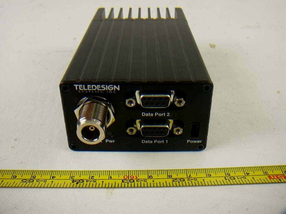
JWFTS4000GH
Oct 28, 2012Radio Modem
Equipment Class
TNB - Licensed Non-Broadcast Station Transmitter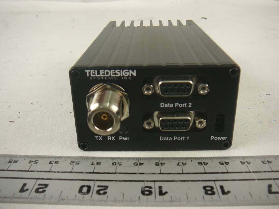
JWFTS4000EL
Apr 06, 2012Radio Modem
Equipment Class
TNB - Licensed Non-Broadcast Station Transmitter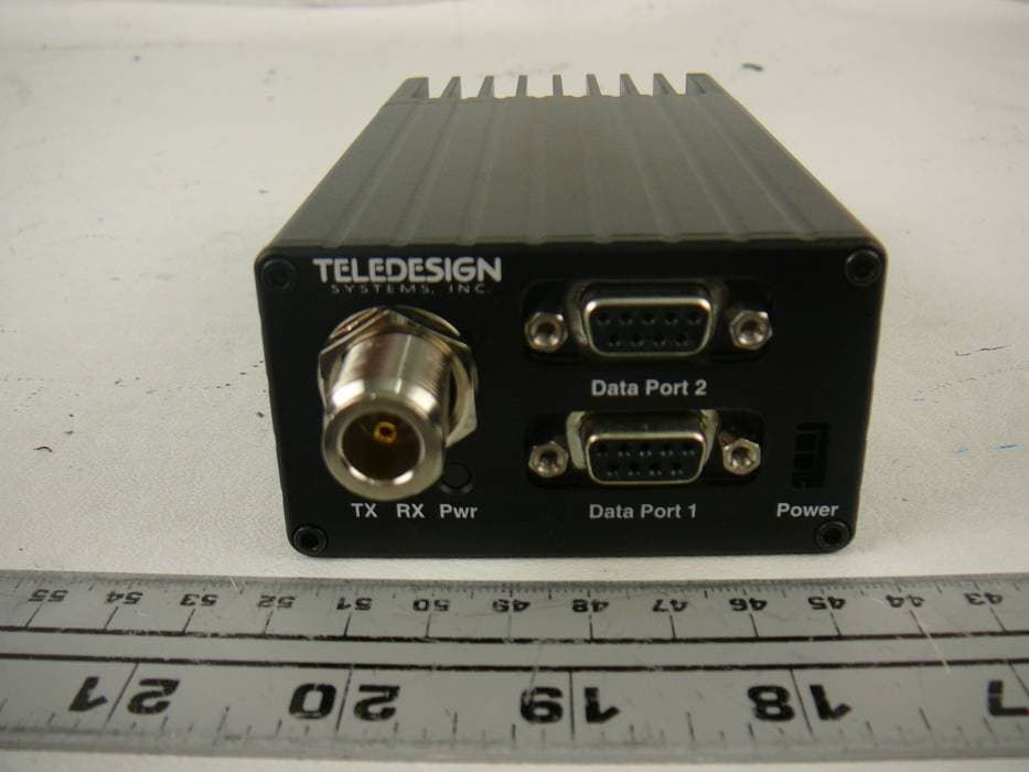
JWFTS4000EH
Apr 06, 2012Radio Modem
Equipment Class
TNB - Licensed Non-Broadcast Station Transmitter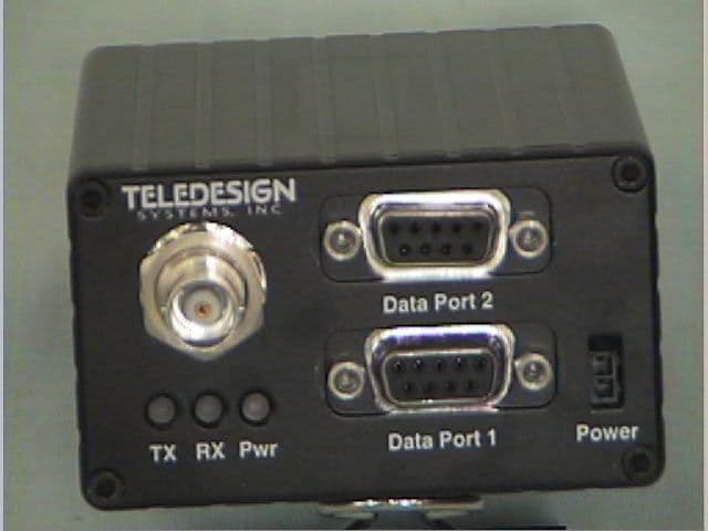
JWFTS4000B
Apr 05, 1999Radio Modem with 3412 Transceiver
Equipment Class
TNB - Licensed Non-Broadcast Station Transmitter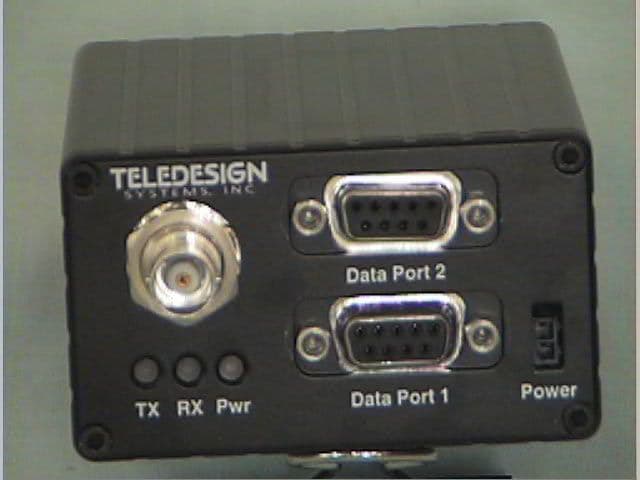
JWFTS4000D
Apr 05, 1999Radio Modem with 3492 Transceiver
Equipment Class
TNB - Licensed Non-Broadcast Station Transmitter