JYCG510PCS 1900 (with WAP & GPRS)
Pantech Co Ltd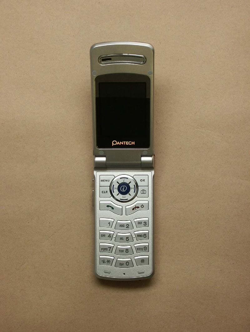
Click to zoom
Application Details
- Equipment Class
- PCE - PCS Licensed Transmitter held to ear
- Date of Grant
- Sep 28, 2003
- Application Purpose
- Original Equipment
- Date of Application
- Sep 28, 2003
- Equipment Note
- PCS 1900 (with WAP & GPRS)
- Frequency Range
- 1850.20000000 - 1909.80000000
- Company
- Pantech Co Ltd
- Country
- South Korea
Documents & Files
Document Text
Text extracted from the exhibit documents filed with the FCC. Open a document above to read the original.
Users Manual
USER MANUAL Characteristic Specification Caution Table of contents Components The mobile phone AC adapter Handset Description * For detail usage of key Antenna Sub display LCD display Microphone Navigation keys Alphanumeric ke ys Menu key N Clear key N Ear-microphone OK key N Side keys Antenna Power Adaptor Connectors Power Adaptor Connectors Camera key Earpiece Camera Side keys Ear-microphone Internal LCD(Main LCD) Sub-LCD Menu options Function keys There are function keys, which have one and more features. Following table shows list of function keys. Function keys Key Icon Name Key Function Quick start Getting started 1. Turn on the phone power 2. Turn off the phone power 3. Make a call 4. End a call 5. Answer a call 6. Adjust the earpiece volume 7. Browse main menu 8. Type numbers and letters on handset Basic call functions Menu functions Before you start T9 options
Cover Letter(s)
___________________________________________________________________________________ ETSHandelsregister:Bankverbindung: Electronic Technology Systems Dr. Genz GmbHAmtsgericht Frankfurt/Oder HRB 5151Sparkasse Oder-Spree Storkower Strasse 38cGeschäftsführung: Dr. Dietmar GenzBLZ 170 550 50 D-15526 Reichenwalde b. Berlin Norbert KasparKto. Nr. 3105165974 ELECTRONIC TECHNOLOGY SYSTEMS DR.GENZ GMBH ELECTRONIC TECHNOLOGY SYSTEMS DR. GENZ GMBH - ETS - STORKOWER STRASSE 38c, D-15526 REICHENWALDE B. BERLIN Tel: 033631 888 000 FAX: 033631 888660 BZT ETS CERTIFICATION GMBH Storkower Str. 38c 15526 Reichenwalde b. Berlin GERMANY IHR ZEICHEN / YOUR REF.IHR SCHREIBEN / YOUR INFORM.UNSER ZEICHEN / OUR REF. DATUM / DATE 29.09.2003 Subject:Application for TCB Certification Applicant: Pantech Co., Ltd. Equipment: PCS 1900 (with WAP & GPRS) FCC ID: JYCG510 Dear Sirs, Submitted herewith, on behalf of Pantech Co., Ltd., is an application for certification under FCC Rule 24 of the following PCS equipment: PCS 1900 (with WAP & GPRS) / FCC ID: JYCG510 Attached are the 731Form, Confidentiality request letter, test report (TestRpt1=test data, TestRpt2=test plots), SAR TestRpt, FCC ID label and label location information, test setup photographs, internal and external photographs, operational description, part’s list, block diagrams, schematics, tune procedure information and user manual. In accordance with 0.459 of CFR 47 Pantech Co., Ltd. hereby requests confidentiality of all Block Diagrams, Circuit Diagrams (Schematics) and Parts List (see attached Confi- dentiality Request Letter) for the subject application. Should you have any questions or comments concerning the above, please contact the following e-mail addresses: [email protected]. Best Regards Jenifer Täubert Electronic Technology Systems Dr. Genz GmbH Storkower Strasse 38c 15526 Reichenwalde bei Berlin Germany e-mail: [email protected]
Cover Letter(s)
Pantech Co., Ltd. Sinsong Center Bldg. 6th Fl., 25-12,Yeouido-dong, Yeoungdeungpo-gu, Seoul, Korea Tel.: +82-2-3660-5862 Fax: +82-2-3660-5990 ______________________________________________________________________ Federal Communications Commission Equipment Authorization Branch 7435 Oakland Mills Road Columbia, MD 21046 Request for Confidentiality
External Photos
ELECTRONIC TECHNOLOGY SYSTEMS DR.GENZ GMBH ETS Dr. Genz GmbH, GermanyRegistration number: G5M203080155-P-24Page 1 of 15 Appendix A. Pictures ELECTRONIC TECHNOLOGY SYSTEMS DR.GENZ GMBH ETS Dr. Genz GmbH, GermanyRegistration number: G5M203080155-P-24Page 2 of 15 ELECTRONIC TECHNOLOGY SYSTEMS DR.GENZ GMBH ETS Dr. Genz GmbH, GermanyRegistration number: G5M203080155-P-24Page 3 of 15 ELECTRONIC TECHNOLOGY SYSTEMS DR.GENZ GMBH ETS Dr. Genz GmbH, GermanyRegistration number: G5M203080155-P-24Page 4 of 15 ELECTRONIC TECHNOLOGY SYSTEMS DR.GENZ GMBH ETS Dr. Genz GmbH, GermanyRegistration number: G5M203080155-P-24Page 5 of 15
ID Label/Location Info
Pantech Co., Ltd. Sinsong Center Bldg. 6th Fl., 25-12,Yeouido-dong, Yeoungdeungpo-gu, Seoul, Korea Tel.: +82-2-3660-5862 Fax: +82-2-3660-5990 ______________________________________________________________________ PCS 1900 (with WAP & GPRS)
ID Label/Location Info
Pantech Co., Ltd. Sinsong Center Bldg. 6th Fl., 25-12,Yeouido-dong, Yeoungdeungpo-gu, Seoul, Korea Tel.: +82-2-3660-5862 Fax: +82-2-3660-5990 ______________________________________________________________________ [FCC ID Label sample] Description: PCS 1900 (with WAP & GPRS) FCC ID: JYCG510
Internal Photos
ELECTRONIC TECHNOLOGY SYSTEMS DR.GENZ GMBH ETS Dr. Genz GmbH, GermanyRegistration number: G5M203080155-P-24Page 5 of 15 ELECTRONIC TECHNOLOGY SYSTEMS DR.GENZ GMBH ETS Dr. Genz GmbH, GermanyRegistration number: G5M203080155-P-24Page 6 of 15 ELECTRONIC TECHNOLOGY SYSTEMS DR.GENZ GMBH ETS Dr. Genz GmbH, GermanyRegistration number: G5M203080155-P-24Page 7 of 15 ELECTRONIC TECHNOLOGY SYSTEMS DR.GENZ GMBH ETS Dr. Genz GmbH, GermanyRegistration number: G5M203080155-P-24Page 8 of 15 ELECTRONIC TECHNOLOGY SYSTEMS DR.GENZ GMBH ETS Dr. Genz GmbH, GermanyRegistration number: G5M203080155-P-24Page 9 of 15 ELECTRONIC TECHNOLOGY SYSTEMS DR.GENZ GMBH ETS Dr. Genz GmbH, GermanyRegistration number: G5M203080155-P-24Page 10 of 15
Operational Description
PreparedReviewConfirm Approval Specification Sheet Approval / / / / Model ZEUS1900 REV. IR No Page 1 of 1 Name JIN HONG PARK Date 2003. 8. 29 Electrical Spec GSM PCS Frequency Range (GHz) 0.88 – 0.96 1.85 – 1.99 TX RX TX RX Band (GHz) 0.88-0.9150.925-0.961.85-1.91 1.93-1.99 FC 3.5 2.5 3.0 3.0 V. S . W. R (Less than) FO 3.0 3.0 3.5 2.5 FC -3.5 -1.5 -4.0 -2.5 Gain(dBi) (Peak Gain , More Than) FO -3.5 -2.0 -3.0 0.5 Nominal Impedance 50 ohms Polarization Vertical Max Input power 2 Watt Mechanical Spec Length 29.5 ±3.0 mm Weight 2.85 g Connector type SCREW TYPE (M4.0 x P0.5) Cover material PA66(KN333HI2) Swivel Torque More Than 3Kgf Pulling force More Than 10Kgf Temperature Range -20 +70 Other AQF04-01-11.E Antenna Radiation Pattern GSM-E1-FOLDER CLOSED G510 Antenna Data(20030828) 1/1 Antenna Radiation Pattern GSM-E1-FOLDER OPENED G510 Antenna Data(20030828) 2/2 Antenna Radiation Pattern GSM-E2-FOLDER CLOSED G510 Antenna Data(20030828) 3/3 Antenna Radiation Pattern GSM-E2-FOLDER OPENED G510 Antenna Data(20030828) 4/4 Antenna Radiation Pattern GSM-H-FOLDER CLOSED G510 Antenna Data(20030828) 5/5 Antenna Radiation Pattern GSM-H-FOLDER OPENED G510 Antenna Data(20030828) 6/6 Antenna Radiation Pattern PCS-E1-FOLDER CLOSED G510 Antenna Data(20030828) 7/7 Antenna Radiation Pattern PCS-E1-FOLDER OPENED G510 Antenna Data(20030828) 8/8 Antenna Radiation Pattern PCS-E2-FOLDER CLOSED G510 Antenna Data(20030828) 9/9 Antenna Radiation Pattern PCS-E2-FOLDER OPENED G510 Antenna Data(20030828) 10/10 Antenna Radiation Pattern PCS-H-FOLDER CLOSED G510 Antenna Data(20030828) 11/11 Antenna Radiation Pattern PCS-H-FOLDER OPENED G510 Antenna Data(20030828) 12/12 Antenna Radiation Pattern VSWR Folder Close G510 Antenna Data(20030828) 13/13 Antenna Radiation Pattern VSWR Folder Open G510 Antenna Data(20030828) 14/14 Antenna Radiation Pattern G510 Antenna Data(20030828) 15/15
Operational Description
G510 Service Manual G510 G510 Service Manual (GSM Cellular Phone) Pantech Co., Ltd., Korea September 5, 2003 1 st Edition For Use by Authorized Service/Maintenance Personal Only Documents to Receive This Addendum: G510 Maintenance/Repair/Operating Manual G510 Service Manual PANTECH R&D CONFIDENTIAL 1 CONTENTS SECTION 1 INTRODUCTION .............................................................................................................3 1.1 INTRODUCTION..............................................................................................................................3 1.2 FREQUENCY ALLOCATION AND ITS USE...........................................................................................3 1.3 ITEM NAME AND USE.....................................................................................................................4 1.4 CHARACTERISTICS........................................................................................................................4 SECTION 2 ELECTRICAL SPECIFICATIONS....................................................................................5 2.1 GENERAL......................................................................................................................................5 2.2 TRANSMITTER..........................................................................................................5 2.3 RECEIVER...............................................................................................................5 SECTION 3 OPERATION....................................................................................................................6 3.1 NAME OF EACH PART...................................................................................................6 3.2.DISPLAY ..................................................................................................................7 3.3 KEYPAD ................................................................................................................7 SECTION 4 THEORY OF OPERATION..............................................................................................8 4.1 LOGIC SECTION ........................................................................................................................8 4.1.1 DC DISTRIBUTION AND REGULATION PART......................................................................8 4.1.2 LOGIC PART..........................................................................................................8 4.1.2.1 SUMMARY..........................................................................................................8 4.1.2.2 BASEBAND DIGITAL SIGNAL PROCESSING....................................................................8 4.1.3 MEMORY PART.....................................................................................................10 4.1.4 NOTIFICATION PART.............................................................................................................. ...11 4.1.5 KEY PAD PART......................................................................................................................... 11 4.1.6 LCD MODULE(DISPLAY PART) .................................................................................................. 11 4.2 RADIO TRANSCEIVER SECTION.....................................................................................................12 4.2.1 DC DISTRIBUTION AND REGULATION PART.................................................................................13 4.2.2 TRANSCEIVER PIN DESCRIPTION.......................................................................14 4.2.3 RECEIVE SECTION.................................................................................................14 4.2.3.1 AN OVERVIEW OF RECEIVE SECTION......................................................................................14 4.2.3.2 RECEIVER PART.................................................................................................155 4.2.4 TRANSMIT SECTION..................................................................................................................17 4.2.4.1 AN OVERVIEW OF TRANSMIT SECTION....................................................................................17 4.2.4.2 TRANSMITTER PART...............................................................................................................18 4.2.5 OFFSET PLL.........................................................................................................19 4.2.5.1 AN OVERVIEW OF OFFSET PLL............................................................................................19 4.2.5.2 VCTCXO(VOLTAGE CONTROLLED TEMPERATURE COMPENSATED CRYSTAL OSCILLATOR):V801....20 SECTION 5 ALIGNMENT PROCEDURE..........................................................................................21 5.1 RECOMMENDED TEST EQUIPMENT...............................................................................................21 5.2 CONNECTION OF TEST EQUIPMENT..............................................................................................21 SECTION 6 EQUIPMENT REPAIR PROCEDURE ...........................................................................22 6.1 NO POWER ON WITH BATTERY APPLIED..........................................................................................22 6.1.1 POWER CHECK.........................................................................................................................22 6.1.2 OSCILLATION CHECK ...............................................................................................................26 6.1.3 KEYPAD LED NOT IN OPERATION(BLUE) ....................................................................................27 6.1.4 LCD EL BACKLIGHT LED NOT IN OPERATION(WHITE).................................................. ...29 6.2 AUDIO PART(EARPIECE, HANDS FREE EARPHONE, MICROPHONE, HANDS FREE MIC) ..........…
Text truncated - open the document above for the full version.
RF Exposure Info
ELECTRONIC TECHNOLOGY SYSTEMS DR. GENZ GMBH TEST - REPORT SAR Compliance Test Report Test report no.: G5M203080155-S-8 SAR ELECTRONIC TECHNOLOGY SYSTEMSSTORKOWER STRASSE 38C, D-15526 REICHENWALDE B. BERLIN DR. GENZ GMBHPHONE +49-33631-888 00 FAX +49-33631-888 660 ETS Dr. Genz GmbH, GermanyRegistration number: G5M203080155-S-8Page 1 of 25 ELECTRONIC TECHNOLOGY SYSTEMS DR.GENZ GMBH TABLE OF CONTENTS 1General information 1.1Notes 1.2Testing laboratory 1.3Details of approval holder 1.4 Manufacturer 1.5Application details 1.6Test item 1.7Test results 1.8Test standards 2Technical test 2.1Summary of test results 2.2Test environment 2.3Test equipment utilized 2.4Definitions 2.5Measurement system description 2.6Test system specification 2.7Measurement procedure 2.8Reference points 2.9Test positions 2.10Measurement uncertainty 3Tissue and system verification 3.1Tissue verification 3.2System verification 4Test Results 5References 6Appendix ETS Dr. Genz GmbH, GermanyRegistration number: G5M203080155-S-8Page 2 of 25 ELECTRONIC TECHNOLOGY SYSTEMS DR.GENZ GMBH 1General Information 1.1Notes The purpose of conformity testing is to increase the probability of adherence to the essential requirements or conformity specifications, as appropriate. The complexity of the technical specifications, however, means that full and thorough testing is impractical for both technical and economic reasons. Furthermore, there is no guarantee that a test sample which has passed all the relevant tests conforms to a specification. The existence of the tests nevertheless provides the confidence that the test sample possesses the qualities as maintained and that is performance generally conforms to representative cases of communications equipment. The test results of this test report relate exclusively to the item tested as specified in 1.5. The test report may only be reproduced or published in full. Reproduction or publication of extracts from the report requires the prior written approval of the ELECTRONIC TECHNOLOGY SYSTEMS DR. GENZ GMBH. I attest to the accuracy of data. All measurements reported herein were performed by me or were made under my supervision and are correct to the best of my knowledge and belief. I assume full responsibility for the completeness of these measurements and vouch for the qualification of all persons taking them. Tester: 29.09.2003N. Kaspar DateETS-Lab.NameSignature Technical responsibility for area of testing: 29.09.2003Dr. Genz DateETSNameSignature ETS Dr. Genz GmbH, GermanyRegistration number: G5M203080155-S-8Page 3 of 25 ELECTRONIC TECHNOLOGY SYSTEMS DR.GENZ GMBH 1.2 Testing laboratory 1.2.1Location ELECTRONIC TECHNOLOGY SYSTEM DR. GENZ GMBH (ETS) Storkower Straße 38c D-15526 Reichenwalde b. Berlin Germany Telephone : +49 33631 888 00 Fax: +49 33631 888 660 1.2.2Details of accreditation status ACCREDITED TESTING LABORATORY DAR-REGISTRATION NUMBER: TTI-P-G 126/96 FCC FILED TEST LABORATORY REG. NO. 96970 BLUETOOTH QUALIFICATION TEST FACILITY (BQTF) ACCREDITED BY BLUETOOTH QUALIFICATION REVIEW BOARD INDUSTRY CANADA FILED TEST LABORATORY REG. NO. IC 3470 A2LA ACCREDITED Certificate Number 1983-01 1.3Details of approval holder Name: Pantech Co., Ltd. Street: Sinsong Center Bldg. 6th Fl., 25-12, Yeouido-dong Town: Yeoungdeungpo-gu, Seoul Country: Korea Telephone: +82-2-3660-5862 Fax: +82-2-3660-5990 Contact: Mr. B.W. Kim E-Mail: [email protected] 1.4Manufacturer: (if applicable) Name: Street: Town: Country: ETS Dr. Genz GmbH, GermanyRegistration number: G5M203080155-S-8Page 4 of 25 ELECTRONIC TECHNOLOGY SYSTEMS DR.GENZ GMBH 1.5Application details Date of receipt of application: 18.08.2003 Date of receipt of test item: 18.08.2003 Date of test: 23.08.2003 - 28.08.2003 1.6Test item FCC ID: JYCG510 Description of test item: Dual Band GSM 900 (E-GSM)/PCS 1900 (with WAP & GPRS) Type identification: G510 Serial number: without;Identical prototype Device category: PCE ( Licensed Portable Transmitter held to ear) Technical data PCS TX Frequency range: 1850,2 - 1909,8 MHz RX Frequency range: 1930,2 - 1989,8 MHz Max. Radiated RF output power: 30,45 dBm (1,109 W) Max. Conducted RF output power : 28,92 dBm (0,779 W) Power supply : 3,7 V DC rechargeable battery Antenna Tx: integral Antenna RX: integral Additional information: Tx and Rx. antenna are the same. This device contains 900 MHz GSM functions are not operational in U.S. Territories. This filing is only applicable for 1900 MHz PCS operations. 1.7Test Results Max. SAR Measurement: 0,958 W/kg (averaged over 1 gram) This EUT has been shown to be capable of compliance for localized specific absorption rate (SAR) for uncontrolled environment/general population exposure limits specified in ANSI/IEEE Std. C95.1-1992 and had been tested in accordance with the measurement procedures specified in FCC/OET Bulletin 65 Supplement C (2001) and IEEE Std. 1528-200X (Draft 6.5, January 2002). ETS Dr. Genz GmbH, GermanyRegistration number: G5M203080155-S-8Page 5 of 25 ELECTRONIC TECHNOLOGY SYSTEMS DR.GENZ GMBH 1.8Test standards Standards: - IEEE Std. 1528-200X (Draft 6.5, January 2002) FCC Rule Part(s): - FCC OET Bulletin 65, Supplement C, Edition 01-01 2Technical test 2.1Summary of test results Applicable Configuration Handset (Head)X Handset (Body)X Headset (Head) Body Worn Equipment EUT complies with the RF radiation exposure limits of the FCC as shown by the SAR measurement results. These measurements are taken to simulate the RF effects exposure under worst-case conditions. The EUT complies with the requirements in respect to all parameters subject to the test. The test results and statements relate only to the item(s) tested. Please note that the absorption and distribution of electromagnetic energy in the body are very complex phenomena that depend on the mass, shape, and size of the body, the orientation of the body with respect to the field vectors, and the electrical properties of both the body and the environment. Other variables that may play a substantial…
Text truncated - open the document above for the full version.
RF Exposure Info
ETS Dr. Genz GmbH, GermanyRegistration number: G5M203080155-S-8Appendix B ELECTRONIC TECHNOLOGY SYSTEMS DR.GENZ GMBH Appendix B Measurement Plots Date/Time: 08/26/03 14:58:43 Test Laboratory: ELECTRONIC TECHNOLOGY SYSTEMS DR. GENZ GMBH File Name: Dipol Valid.1900(h)_26.08.03.da4 Dipol Valid.1900(h)_26.08.03 DUT: Dipole 1900 MHz; Type: D1900V2; Serial: 5d025 Program: Dipol Valid 1900 Communication System: CW; Frequency: 1900 MHz;Duty Cycle: 1:1 Medium: Head 1900 MHz (σ = 1.41529 mho/m, ε r = 39.8679, ρ = 1000 kg/m 3 ) Phantom section: Flat Section DASY4 Configuration: z Probe: ET3DV6 - SN1711; ConvF(5.3, 5.3, 5.3); Calibrated: 11/29/2002 z Sensor-Surface: 4mm (Mechanical And Optical Surface Detection) z Electronics: DAE3 Sn522; Calibrated: 9/11/2002 z Phantom: SAM 12; Type: TP-1217; Serial: QD000P40CA z Measurement SW: DASY4, V4.1 Build 47; Postprocessing SW: SEMCAD, V1.6 Build 115 Dipol 1900 (17dBm)/Area Scan (81x81x1): Measurement grid: dx=10mm, dy=10mm Reference Value = 41.9 V/m Power Drift = 0.1 dB Maximum value of SAR = 2.28 mW/g Dipol 1900 (17dBm)/Zoom Scan (7x7x7)/Cube 0: Measurement grid: dx=5mm, dy=5mm, dz=5mm Peak SAR (extrapolated) = 3.81 W/kg SAR(1 g) = 2.09 mW/g; SAR(10 g) = 1.07 mW/g Reference Value = 41.9 V/m Power Drift = 0.1 dB Maximum value of SAR = 2.34 mW/g 0 dB = 2.34mW/g Page 1 of 1 8/26/2003file://C:\TEMP\Dipol%20Valid.1900(h)_26.08.03-1.htm Date/Time: 08/27/03 13:15:44 Test Laboratory: ELECTRONIC TECHNOLOGY SYSTEMS DR. GENZ GMBH File Name: Dipol Valid.1900(h)_27.08.03.da4 Dipol Valid.1900(h)_27.08.03 DUT: Dipole 1900 MHz; Type: D1900V2; Serial: 5d025 Program: Dipol Valid 1900 Communication System: CW; Frequency: 1900 MHz;Duty Cycle: 1:1 Medium: Head 1900 MHz (σ = 1.41529 mho/m, ε r = 39.8679, ρ = 1000 kg/m 3 ) Phantom section: Flat Section DASY4 Configuration: z Probe: ET3DV6 - SN1711; ConvF(5.3, 5.3, 5.3); Calibrated: 11/29/2002 z Sensor-Surface: 4mm (Mechanical And Optical Surface Detection) z Electronics: DAE3 Sn522; Calibrated: 9/11/2002 z Phantom: SAM 12; Type: TP-1217; Serial: QD000P40CA z Measurement SW: DASY4, V4.1 Build 47; Postprocessing SW: SEMCAD, V1.6 Build 115 Dipol 1900 (17dBm)/Area Scan (81x81x1): Measurement grid: dx=10mm, dy=10mm Reference Value = 42.0 V/m Power Drift = 0.12 dB Maximum value of SAR = 2.3 mW/g Dipol 1900 (17dBm)/Zoom Scan (7x7x7)/Cube 0: Measurement grid: dx=5mm, dy=5mm, dz=5mm Peak SAR (extrapolated) = 3.83 W/kg SAR(1 g) = 2.1 mW/g; SAR(10 g) = 1.09 mW/g Reference Value = 42.0 V/m Power Drift = 0.12 dB Maximum value of SAR = 2.36 mW/g 0 dB = 2.36mW/g Page 1 of 1 8/27/2003file://C:\TEMP\Dipol%20Valid.1900(h)_27.08.03-1.htm Date/Time: 08/28/03 07:41:33 Test Laboratory: ELECTRONIC TECHNOLOGY SYSTEMS DR. GENZ GMBH File Name: Dipol Valid.1900(h)_28.08.03.da4 Dipol Valid.1900(h)_28.08.03 DUT: Dipole 1900 MHz; Type: D1900V2; Serial: 5d025 Program: Dipol Valid 1900 Communication System: CW; Frequency: 1900 MHz;Duty Cycle: 1:1 Medium: Head 1900 MHz (σ = 1.41529 mho/m, ε r = 39.8679, ρ = 1000 kg/m 3 ) Phantom section: Flat Section DASY4 Configuration: z Probe: ET3DV6 - SN1711; ConvF(5.3, 5.3, 5.3); Calibrated: 11/29/2002 z Sensor-Surface: 4mm (Mechanical And Optical Surface Detection) z Electronics: DAE3 Sn522; Calibrated: 9/11/2002 z Phantom: SAM 12; Type: TP-1217; Serial: QD000P40CA z Measurement SW: DASY4, V4.1 Build 47; Postprocessing SW: SEMCAD, V1.6 Build 115 Dipol 1900 (17dBm)/Area Scan (81x81x1): Measurement grid: dx=10mm, dy=10mm Reference Value = 41.7 V/m Power Drift = -0.04 dB Maximum value of SAR = 2.2 mW/g Dipol 1900 (17dBm)/Zoom Scan (7x7x7)/Cube 0: Measurement grid: dx=5mm, dy=5mm, dz=5mm Peak SAR (extrapolated) = 3.53 W/kg SAR(1 g) = 1.97 mW/g; SAR(10 g) = 1.02 mW/g Reference Value = 41.7 V/m Power Drift = -0.04 dB Maximum value of SAR = 2.2 mW/g 0 dB = 2.2mW/g Page 1 of 1 8/28/2003file://C:\TEMP\Dipol%20Valid.1900(h)_28.08.03-1.htm Date/Time: 08/27/03 17:25:20 Test Laboratory: ELECTRONIC TECHNOLOGY SYSTEMS DR. GENZ GMBH File Name: 1900_right_ch512_cheek.da4 1900_right_ch512_cheek DUT: Dual Band GSM900 (EGSM) / PCS1900 (with WAP & GPRS); Type: -; Serial: G510 Program: PCS 1900 Communication System: GSM 1900; Frequency: 1850.2 MHz;Duty Cycle: 1:8 Medium: Head 1900 MHz (σ = 1.3685 mho/m, ε r = 39.9283, ρ = 1000 kg/m 3 ) Phantom section: Right Section DASY4 Configuration: z Probe: ET3DV6 - SN1711; ConvF(5.3, 5.3, 5.3); Calibrated: 11/29/2002 z Sensor-Surface: 4mm (Mechanical And Optical Surface Detection) z Electronics: DAE3 Sn522; Calibrated: 9/11/2002 z Phantom: SAM 12; Type: TP-1217; Serial: QD000P40CA z Measurement SW: DASY4, V4.1 Build 47; Postprocessing SW: SEMCAD, V1.6 Build 115 G510/Area Scan (101x141x1): Measurement grid: dx=10mm, dy=10mm Reference Value = 7.15 V/m Power Drift = 0.04 dB Maximum value of SAR = 0.567 mW/g G510/Zoom Scan (7x7x7)/Cube 0: Measurement grid: dx=5mm, dy=5mm, dz=5mm Peak SAR (extrapolated) = 0.809 W/kg SAR(1 g) = 0.511 mW/g; SAR(10 g) = 0.284 mW/g Reference Value = 7.15 V/m Power Drift = 0.04 dB Maximum value of SAR = 0.564 mW/g 0 dB = 0.564mW/g Page 1 of 1 8/28/2003file://C:\TEMP\1900_right_ch512_cheek-5.htm Date/Time: 08/26/03 21:47:33 Test Laboratory: ELECTRONIC TECHNOLOGY SYSTEMS DR. GENZ GMBH File Name: 1900_right_ch512_tilted.da4 1900_right_ch512_tilted DUT: Dual Band GSM900 (EGSM) / PCS1900 (with WAP & GPRS); Type: -; Serial: G510 Program: PCS 1900 Communication System: GSM 1900; Frequency: 1850.2 MHz;Duty Cycle: 1:8 Medium: Head 1900 MHz (σ = 1.3685 mho/m, ε r = 39.9283, ρ = 1000 kg/m 3 ) Phantom section: Right Section DASY4 Configuration: z Probe: ET3DV6 - SN1711; ConvF(5.3, 5.3, 5.3); Calibrated: 11/29/2002 z Sensor-Surface: 4mm (Mechanical And Optical Surface Detection) z Electronics: DAE3 Sn522; Calibrated: 9/11/2002 z Phantom: SAM 12; Type: TP-1217; Serial: QD000P40CA z Measurement SW: DASY4, V4.1 Build 47; Postprocessing SW: SEMCAD, V1.6 Build 115 G510/Area Scan (101x141x1): Measurement grid: dx=10mm, dy=10mm Reference Value = 9.1 V/m Power Drift = 0.02 dB Maximum value of SAR = 0…
Text truncated - open the document above for the full version.
RF Exposure Info
ETS Dr. Genz GmbH, GermanyRegistration number: G5M203080155-S-8Appendix C ELECTRONIC TECHNOLOGY SYSTEMS DR.GENZ GMBH Appendix C Pictures ELECTRONIC TECHNOLOGY SYSTEMS DR.GENZ GMBH ETS Dr. Genz GmbH, GermanyRegistration number: G5M203080155-S-8Page 1 of 11 Appendix A. Pictures ELECTRONIC TECHNOLOGY SYSTEMS DR.GENZ GMBH ETS Dr. Genz GmbH, GermanyRegistration number: G5M203080155-S-8Page 2 of 11 ELECTRONIC TECHNOLOGY SYSTEMS DR.GENZ GMBH ETS Dr. Genz GmbH, GermanyRegistration number: G5M203080155-S-8Page 3 of 11 ELECTRONIC TECHNOLOGY SYSTEMS DR.GENZ GMBH ETS Dr. Genz GmbH, GermanyRegistration number: G5M203080155-S-8Page 4 of 11 ELECTRONIC TECHNOLOGY SYSTEMS DR.GENZ GMBH ETS Dr. Genz GmbH, GermanyRegistration number: G5M203080155-S-8Page 5 of 11 ELECTRONIC TECHNOLOGY SYSTEMS DR.GENZ GMBH ETS Dr. Genz GmbH, GermanyRegistration number: G5M203080155-S-8Page 6 of 11 ELECTRONIC TECHNOLOGY SYSTEMS DR.GENZ GMBH ETS Dr. Genz GmbH, GermanyRegistration number: G5M203080155-S-8Page 7 of 11 ELECTRONIC TECHNOLOGY SYSTEMS DR.GENZ GMBH ETS Dr. Genz GmbH, GermanyRegistration number: G5M203080155-S-8Page 8 of 11 ELECTRONIC TECHNOLOGY SYSTEMS DR.GENZ GMBH ETS Dr. Genz GmbH, GermanyRegistration number: G5M203080155-S-8Page 9 of 11 ELECTRONIC TECHNOLOGY SYSTEMS DR.GENZ GMBH ETS Dr. Genz GmbH, GermanyRegistration number: G5M203080155-S-8Page 10 of 11 ELECTRONIC TECHNOLOGY SYSTEMS DR.GENZ GMBH ETS Dr. Genz GmbH, GermanyRegistration number: G5M203080155-S-8Page 11 of 11
Test Report
ELECTRONIC TECHNOLOGY SYSTEMS DR. GENZ GMBH TEST - REPORT FCC RULES PART 24 Test report no.: G5M203080155-P-24 FCC ID: JYCG510 FCC ELECTRONIC TECHNOLOGY SYSTEMSSTORKOWER STRASSE 38C, D-15526 REICHENWALDE B. BERLIN DR. GENZ GMBHPHONE +49-33631-888 00 FAX +49-33631-888 66 ETS Dr. Genz GmbH, GermanyRegistration number: G5M203080155-P-24Page 1 of 25 ELECTRONIC TECHNOLOGY SYSTEMS DR.GENZ GMBH TABLE OF CONTENTS 1General information 1.1Notes 1.2Testing laboratory 1.3Details of approval holder 1.4Application details 1.5Test item 1.6Test standards 2Technical test 2.1Summary of test results 2.2Test environment 2.3Test equipment utilized 3 Test Results 4 RF Power Output, FCC 2.1046 4.1 Test Procedure 4.2 Test Results 5 Radiated Power, FCC 24.232 5.1 Test Procedure 5.2 Test Results 6 Occupied Bandwidth, FCC 2.1049 6.1 Test Procedure 6.2 Test Results 7 Field Strength of Spurious Radiations, FCC 2.1053, 24.238 7.1 Test Procedure 7.2 Test Results 8 Line Conducted Emissions, FCC 15.207 8.1 Test Procedure 8.2 Test Results 9 Frequency Stability vs Temperature, FCC 2.1055, 24.235 9.1 Test Procedure 9.2 Test Results 10 Frequency Stability vs Voltage, FCC 2.1055, 24.235 10.1 Test Procedure 10.2 Test Equipment ETS Dr. Genz GmbH, GermanyRegistration number: G5M203080155-P-24Page 2 of 25 ELECTRONIC TECHNOLOGY SYSTEMS DR.GENZ GMBH 1General Information 1.1Notes The purpose of conformity testing is to increase the probability of adherence to the essential requirements or conformity specifications, as appropriate. The complexity of the technical specifications, however, means that full and thorough testing is impractical for both technical and economic reasons. Furthermore, there is no guarantee that a test sample which has passed all the relevant tests conforms to a specification. Neither is there any guarantee that such a test sample will interwork with other genuinely open systems. The existence of the tests nevertheless provides the confidence that the test sample possesses the qualities as maintained and that is performance generally conforms to representative cases of communications equipment. The test results of this test report relate exclusively to the item tested as specified in 1.5. The test report may only be reproduced or published in full. Reproduction or publication of extracts from the report requires the prior written approval of the ELECTRONIC TECHNOLOGY SYSTEMS DR. GENZ GMBH. Tester: 23.09.2003Mr. Schulz DateETS-Lab.NameSignature Technical responsibility for area of testing: 23.09.2003Dr. Genz DateETSNameSignature ETS Dr. Genz GmbH, GermanyRegistration number: G5M203080155-P-24Page 3 of 25 ELECTRONIC TECHNOLOGY SYSTEMS DR.GENZ GMBH 1.2 Testing laboratory 1.2.1Location ELECTRONIC TECHNOLOGY SYSTEM DR. GENZ GMBH (ETS) Storkower Straße 38c D-15526 Reichenwalde b. Berlin Germany Telefon : +49 33631 888 00 Telefax : +49 33631 888 660 1.2.2Details of accreditation status A CCREDITED TESTING LABORATORY DAR-REGISTRATION NUMBER: TTI-P-G 126/96 ACCREDITED COMPETENT BODY DAR-REGISTRATION NUMBER: BPT-ZE-026/96 FCC FILED TEST LABORATORY REG. NO. 96970 BLUETOOTH QUALIFICATION TEST FACILITY (BQTF) ACCREDITED BY: BLUETOOTH QUALIFICATION REVIEW BOARD (BQRF) I NDUSTRY CANADA FILED TEST LABORATORY REG. NO. IC 3470 A2LA A CCREDITEDCertificate Number: 1983-01 1.3Details of approval holder Name: Pantech Co., Ltd. Street: Sinsong Center Bldg. 6th Fl., 25-12, Yeouido-dong Town: Yeoungdeungpo-gu, Seoul Country: Korea Telephone: +82-2-3660-5862 Fax: +82-2-3660-5990 Contact: Mr. B.W. Kim Email: [email protected] ETS Dr. Genz GmbH, GermanyRegistration number: G5M203080155-P-24Page 4 of 25 ELECTRONIC TECHNOLOGY SYSTEMS …
Text truncated - open the document above for the full version.
Contact Information
Applicant
Bum-Young Lee(Vice President)
Technical Contact
Pantech Co., Ltd.Byung-Wan Kim
[email protected]822 3660 5862
Singsong Center Bldg. 6th Fl., · Seoul · South Korea
Test Firm
Eurofins Product Service GmbHRobert Kschiwan-Kaspar
Technical Specifications
| # | Rule Parts | Frequency Range | Power Output | Emission | Tolerance |
|---|---|---|---|---|---|
| 1 | 24E | 1.85 GHz - 1.91 GHz | 1.109 W | 246KGXW | 1.0000000000 ppm |
Other Applications from Pantech Co Ltd
JYCP2050
Aug 04, 2013GSM/WCDMA Phone with Bluetooth
Equipment Class
PCE - PCS Licensed Transmitter held to ear
JYCORBIT
Feb 19, 2013CDMA/PCS,GSM,WCDMA,LTE Portable Router with WLAN
Equipment Class
PCB - PCS Licensed Transmitter
JYCPREMIAV
Sep 06, 2012CDMA/GSM/LTE Phone with BT/WLAN/NFC
Equipment Class
DTS - Digital Transmission System
JYCCDMAPTL21
Aug 29, 2012GSM/WCDMA/CDMA Phone with Bluetooth/WLAN/NFC
Equipment Class
DSS - Part 15 Spread Spectrum Transmitter
JYCSPARKLE
Aug 21, 2012CDMA/GSM/EDGE/WCDMA/LTE USB Data Dongle
Equipment Class
PCB - PCS Licensed Transmitter