JYCPG-1210Triple Band GSM850/ DCS1800/ PCS1900 (w. WAP&GPRS)
Pantech Co Ltd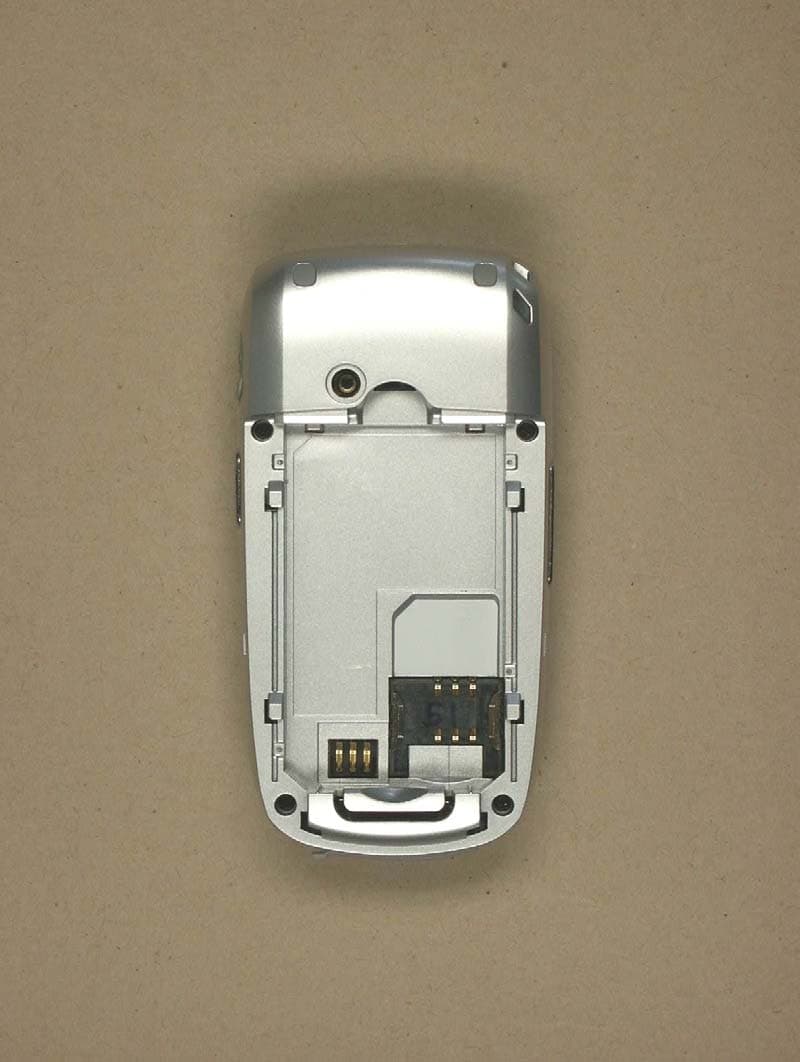
Click to zoom
Application Details
- Equipment Class
- PCE - PCS Licensed Transmitter held to ear
- Date of Grant
- Jun 01, 2005
- Application Purpose
- Original Equipment
- Date of Application
- Jun 01, 2005
- Equipment Note
- Triple Band GSM850/ DCS1800/ PCS1900 (w. WAP&GPRS)
- Frequency Range
- 824.20000000 - 848.80000000
- Company
- Pantech Co Ltd
- Country
- South Korea
Documents & Files
Document Text
Text extracted from the exhibit documents filed with the FCC. Open a document above to read the original.
Users Manual
USER’S MANUAL PG-1210 Thank you for choosing Pantech PG-1210 and welcome to wireless mobile communication networking with the PG-1210, our tri-band GSM mobile phone. Pantech is delighted to introduce this brand new portable phone which will always keep you conne cted to the network. This user manual explains in detail its unique features and how to use them. NOTE : Some of the contents in this User Manual could vary from your phone. It may vary depending on the S/W version and the network provider you subscribed to. 2 Specification Display Dual clamshell 65K CSTN LCD internal and 65K CSTN external. z 30.54 mm x 36.04 mm display for 1.8” internal LCD z 22.96 mm x 16.48 mm display for 1.0” external LCD z Supports up to 65,536 colors within 128 x 160 pixels internal and 96 x 64 pixels external z 8 lines for text in basic mode with 18-pixel font z Two Soft keys and four-way scroll and selection ([ OK ]) keys Melody General Midi 64 poly sound (Support MP3 Ringtones ( 지원 포맷 : mpeg-1, mpeg-2 )) Camera Integrated VGA CMOS Camera(330k). z Resolution up to 640 x 480 (310,000 pixels) z Self timer function (5 sec or 10 sec) z Phone display used as a viewfinder z Photo album in Gallery z Photo Gallery for image storing and editing z 3 image quality options: Fine, Normal, Low z mjpeg recording / playing z continuous capture supported Dimension & Weight z Weight: 91.5 g z Dimensions: 90 x 45.5 x 23.3 mm Power Management (Performance) Battery Type Capacity Standby Time Talk Time Standard (Li-ion) 700 mAh 180 Hours 3 Hours Operating Frequency z GSM 850, GSM 1800, GSM 1900 : 1800Mhz networks in Europe, Africa, Asia-Pacific, North America, and South America where these networks are supported z Automatic band switching 3 Views Ear p iece Microphone Power On/Off Me nu exit key Headset Jack Left Soft ke y DiaI key Call Accept Voicemail A l p hanumeric ke y Cancel/Back Text Clear/Edit exit key 4-way Menu Navigation Special Menu Short key Volume up/down Menu Scroll WAP Access key Select/Menu Confirm ke y Phone Lock/Unlock Camera ke y Internal LCD Microphone Vibration Mode Right Soft key Camera 4 Quick & Easy Key Function ( Left/Right ) Performs the functions shown at the bottom line of the display. Scrolls through the menu options in Menu mode. In standby mode, Left key ( ): Favorite list screen Right key ( ): Messages menu screen Up key ( ): Sound Settings menu for sound change. Down key ( ): Contacts screen to find contact names. For details, see “Using the Shortcut Key in Standby Mode”. Opens the WAP (Wireless Application Protocol) menu list if pressed shortly in standby mode Launches the WAP browser directly, if pressed and held in standby mode. Selects a menu functions which stores user input information, such as names, SIM memory. Also used for confirmation. Deletes characters from the display, or returns to previous menu. Opens Calendar view if pressed shortly in standby mode. Sends or receives a call. Shows the recent call list in standby mode. Re-dials the last call number if pressed and held in standby mode. Completes the current call. Turns on/off the phone if pressed and held. Cancels user input and returns to standby mode while in Menu mode. Quickly connects to the voice mail server if pressed and held in standby mode. ~ Enters numbers, letters or special characters. Goes to the dial screen if pressed in standby mode. Enters or exits from Vibration mode if pressed and held in standby mode. Shows the symbol input screen if pressed in text input mode. Works in Word search mode if pressed in the Predictive text input mode. Enters an international dialling prefix. Enters the space character in text input mode. Locks or unlocks the phone if pressed and held in standby mode.(default password : “1234”) Changes various text input modes if pressed and held at the text-editing screen. Adjusts the earpiece volume while making a call, and moves the cursor upwards or downwards in the menu. Controls the key tone volume in standby mode if the phone flip is opened. Turns camera capture mode on. Works as a camera shutter in capture mode. Turns Video Mode on if pressed and held. 5 Safety Precautions Using a phone while driving is prohibited. Please check local laws and regulations with regard to the prohibition of phone usage while driving, and comply with them. - Use of your mobile phone while you are driving may disturb your concentration and consequently cause acci dents. Please turn it off as soon as possible. - Should you use your phone in an emergency, please make use of the hands free device built in your car, or pull your car over to a safe place for your utmost safety. - The electronic wave energy emitting from your phone may affect the electronic devices built in your car. Pl ease be aware of this characteristic. Mobile Phone Use Restriction Area Make sure to turn your phone off in a phone usage restricted area. Using a Phone in an Explosive or Dangerous Area is not Permitted Please turn your phone off in areas with explosive or dangerous materials (such as fuel, fuel stations, or pl aces with chemical goods) and abide by any instructions or signals. Never tr y to detach your mobile phone battery from the phone in such areas. Boarding an Aircraft - Please turn your phone off when you are on the aircraft. The electronic wave from your phone may affect the electronic navigation device in the aircraft. Using Medical Equipment - Please turn your phone off while you are in a hospital. - Please abide by the regulations or rules of the hospital. - Please turn off your phone when using medical equipment for private purposes if possible. You should consult with the manufacturer or an expert regarding phone usage near medical equipment. Installing a Vehicle Hands Free Device - Please keep the vehicle hands free device away from the steering, and air bag expansion range, or otherwise injury may result. Effect of Mobile Phone and Electronic Devices Some electronic devices may be affect ed by the electronic wave emitti…
Text truncated - open the document above for the full version.
Block Diagram
PG 1210 Block Diagram BB US CR I US CR X US C R TX US C C TS US C R TS V O IC EB AN D/ B A SE BA ND CO DE C INTER F AC E CH AN NE L EQU A L I ZE R CO NT R O L P R O C ES SO R RA DI O INTER F AC E AC CE SS O R Y I N T E RF AC E KE YP AD / BA CK L I GHT I N T E RF AC E SP EE CH CODE C JTAG SI M C A R D SI MD ATA SIM C L K S I MR ES ET SI M S U PPL Y FLA SH PW D ROMC S RA MC S GP C S AD D[ 0 : 23 ] DA T A [ 0 : 1 5] DI S P L A Y I N T E RF AC E SI M I N T E RF AC E TES T I N T E RF AC E U N I V ER SA L SY STE M CON N . I N T E RF AC E AD6527( GSM Digi t al B aseband Processor ) SPE A K E R MI C RADI O INTE R F ACE RADIO INTERFACE CH AN NE L CODE C DS P MCU SY ST EM SR AM ME MO RY I N T E RF AC E AS P O R T Fil t er Fil t er Sw itc h MI C Fil t er He ad s e t DA C DA C ADC TONE CS P O R T BS P O R T Li g h t Co nt r o lle rs LE D Cr y s t a l GM SK Fi lt er Fi lt er AD C AD C AD C DACDACDACDAC AD6537B( GSM Analog Baseband Processor ) Co m p an y pr op ri et ary LOW - IF DIGITAL FILTER LNA AD C 0/9 0 Φ DE T LNA PGAPGA AD C DI V 2 GS M850 PC S BASE BAND I Q AFC CLK 26M Hz V C TCXO VC-TCXO-214C6 DCS PA M S KY7 7325 Company proprietary RF T RA NSCE IVE R S I 4210 PG-1 21 0 Block Diagr a m RF PA LNALNA PGAPGA ANALOG INTERFACE VCO + FREQU E NCY SYNTHESIZER XO U T GS M 8 50 DCS/P CS SA W Fi lter AS M HITA CHI ME T A L SH S - M 0 85 TK
Cover Letter(s)
Pantech Co., Ltd. Sinsong Center Bldg. 6th Fl., 25-12,Yeouido-dong, Yeoungdeungpo-gu, Seoul, Korea Tel.: +82-2-3660-5862 Fax: +82-2-3660-5990 ______________________________________________________________________ LETTER OF AUTHORIZATION DATE : May 25, 2005 To whom it may concern: We the undersigned, hereby authorize ETS Germany to act on our behalf in all manners relating to application for equipment authorization, including signing of all documents relating to these matters. Any and all acts carried out by ETS Germany on our behalf shall have the same affect as acts of our own. This authorization is valid until further written notice from Pantech Co.,LTd. Sincerely, (Company counsel or company officer signature) Name : Byung-Wan Kim Title : Vice President (Name and Title)
External Photos
ELECTRONIC TECHNOLOGY SYSTEMS DR.GENZ GMBH ETS Dr. Genz GmbH, Germany Registration number: G5M205040023-P-2224 Page 1 of 15 Appendix A. Pictures ELECTRONIC TECHNOLOGY SYSTEMS DR.GENZ GMBH ETS Dr. Genz GmbH, Germany Registration number: G5M205040023-P-2224 Page 2 of 15 ELECTRONIC TECHNOLOGY SYSTEMS DR.GENZ GMBH ETS Dr. Genz GmbH, Germany Registration number: G5M205040023-P-2224 Page 3 of 15 ELECTRONIC TECHNOLOGY SYSTEMS DR.GENZ GMBH ETS Dr. Genz GmbH, Germany Registration number: G5M205040023-P-2224 Page 4 of 15 ELECTRONIC TECHNOLOGY SYSTEMS DR.GENZ GMBH ETS Dr. Genz GmbH, Germany Registration number: G5M205040023-P-2224 Page 5 of 15 ELECTRONIC TECHNOLOGY SYSTEMS DR.GENZ GMBH ETS Dr. Genz GmbH, Germany Registration number: G5M205040023-P-2224 Page 6 of 15 ELECTRONIC TECHNOLOGY SYSTEMS DR.GENZ GMBH ETS Dr. Genz GmbH, Germany Registration number: G5M205040023-P-2224 Page 7 of 15
ID Label/Location Info
Pantech Co., Ltd. Sinsong Center Bldg. 6th Fl., 25-12,Yeouido-dong, Yeoungdeungpo-gu, Seoul, Korea Tel.: +82-2-3660-5862 Fax: +82-2-3660-5990 ______________________________________________________________________ [Label Location] Description: Triple Band GSM 850 /DCS 1800 /PCS 1900 (with WAP & GPRS) FCC ID: JYCPG-1210
ID Label/Location Info
Pantech Co., Ltd. Sinsong Center Bldg. 6th Fl., 25-12,Yeouido-dong, Yeoungdeungpo-gu, Seoul, Korea Tel.: +82-2-3660-5862 Fax: +82-2-3660-5990 ______________________________________________________________________ [FCC ID Label sample] Description: Triple Band GSM 850/DCS 1800 /PCS 1900 (with WAP & GPRS) FCC ID: JYCPG-1210
Internal Photos
ELECTRONIC TECHNOLOGY SYSTEMS DR.GENZ GMBH ETS Dr. Genz GmbH, Germany Registration number: G5M205040023-P-2224 Page 8 of 15 ELECTRONIC TECHNOLOGY SYSTEMS DR.GENZ GMBH ETS Dr. Genz GmbH, Germany Registration number: G5M205040023-P-2224 Page 9 of 15 ELECTRONIC TECHNOLOGY SYSTEMS DR.GENZ GMBH ETS Dr. Genz GmbH, Germany Registration number: G5M205040023-P-2224 Page 10 of 15 ELECTRONIC TECHNOLOGY SYSTEMS DR.GENZ GMBH ETS Dr. Genz GmbH, Germany Registration number: G5M205040023-P-2224 Page 11 of 15 ELECTRONIC TECHNOLOGY SYSTEMS DR.GENZ GMBH ETS Dr. Genz GmbH, Germany Registration number: G5M205040023-P-2224 Page 12 of 15
Operational Description
PG-1210 Service Manual PG-1210 PG-1210 Service Manual (GSM Cellular Phone) Pantech Co., Ltd., Korea May 26, 2005 1 st Edition For Use by Authorized Service/Maintenance Personal Only Documents to Receive This Addendum: PG-1210 Maintenance/Repair/Operating Manual PG-1210 Service Manual CONTENTS SECTION 1 INTRODUCTION.............................................................................................................3 1.1 AN INTRODUCTION OF GSM DIGITAL CELLULAR MOBILE COMMUNICATION SYSTEM..........................3 1.2 FREQUENCY ALLOCATION AND ITS USE...........................................................................................3 1.3 ITEM NAME AND USE.....................................................................................................................4 1.4 CHARACTERISTICS........................................................................................................................4 SECTION 2 ELECTRICAL SPECIFICATIONS....................................................................................5 2.1 GENERAL......................................................................................................................................5 2.2 TRANSMITTER..........................................................................................................5 2.3 RECEIVER...............................................................................................................5 SECTION 3 OPERATION....................................................................................................................6 3.1 NAME OF EACH PART...................................................................................................6 3.2.DISPLAY ..................................................................................................................7 3.3 KEYPAD ................................................................................................................7 3.4 CAMERA MODULE..................................................................................................7 SECTION 4 THEORY OF OPERATION..............................................................................................8 4.1 LOGIC SECTION........................................................................................................................8 4.1.1 DC DISTRIBUTION AND REGULATION PART......................................................................8 4.1.2 LOGIC PART..........................................................................................................8 4.1.2.1 SUMMARY..........................................................................................................8 4.1.2.2 BASEBAND DIGITAL SIGNAL PROCESSING....................................................................8 4.1.3 MEMORY PART.....................................................................................................10 4.1.4 NOTIFICATION PART..................................................................................................................11 4.1.5 KEY PAD PART.........................................................................................................................11 4.1.6 LCD MODULE(DISPLAY PART) ..................................................................................................11 4.1.7 CAMERA MODULE 4.2 RADIO TRANSCEIVER SECTION.....................................................................................................12 4.2.1 DC DISTRIBUTION AND REGULATION PART.................................................................................13 4.2.3 RECEIVER SECTION..............................................................................................13 4.2.3.1 AN OVERVIEW OF RECEIVE SECTION......................................................................................13 4.2.3.2 RECEIVER PART.................................................................................................14 4.2.4 TRANSMIT SECTION..................................................................................................................15 4.2.4.1 AN OVERVIEW OF TRANSMIT SECTION....................................................................................15 4.2.4.2 TRANSMITTER PART...............................................................................................................16 4.2.5. VCTCXO(VOLTAGE CONTROLLED TEMPERATURE COMPENSATED CRYSTAL OSCILLATOR):.............16 SECTION 5 ALIGNMENT PROCEDURE..........................................................................................17 5.1 RECOMMENDED TEST EQUIPMENT...............................................................................................17 5.2 CONNECTION OF TEST EQUIPMENT..............................................................................................17 SECTION 6 EQUIPMENT REPAIR PROCEDURE...........................................................................18 6.1 NO POWER ON WITH BATTERY APPLIED..........................................................................................18 6.1.1 POWER CHECK.........................................................................................................................18 6.1.2 OSCILLATION CHECK ...............................................................................................................24 6.1.3 KEYPAD LED NOT IN OPERATION...............................................................................................25 6.1.4 LCD BACKLIGHT LED NOT IN OPERATION(WHITE)....................................................... ...26 6.2 AUDIO PART(EARPIECE, HANDS FREE EARPHONE, MICROPHONE, HANDS FREE MIC) ..................27 6.2.1 NO RECEIVING TONE HEARD (EARPIECE) .................................................................................27 6.2.2 NO RECEIVING TONE HEARD (HANDS FREE EARPHONE).............................................................28 6.2.3 SIDETONE NOT TRANSMITTED …
Text truncated - open the document above for the full version.
Parts List/Tune Up Info
Pantech Co., Ltd. Sinsong Center Bldg. 6th Fl., 25-12,Yeouido-dong, Yeoungdeungpo-gu, Seoul, Korea Tel.: +82-2-3660-5862 Fax: +82-2-3660-5990 __________________________________________________________________________________ Date: 2005. 05 Federal Communications Commission Equipment Authorization Branch 7435 Oakland Mills Road Columbia, MD 21046 Declaration – Tuning Procedure Pantech Co., Ltd. FCC ID: JYCPG-1210 FCC Part 2, 24 Certification Gentlemen, There are no user accessible adjustments or tuning for this Triple Band GSM 850 /DCS 1800 /PCS 1900 (with WAP & GPRS). All necessary adjustments and tuning are performed during manufacture of the product. Sincerely, Byung-Wan Kim Vice President Pantech Co., Ltd.
RF Exposure Info
Pantech Co., Ltd. Sinsong Center Bldg. 6th Fl., 25-12,Yeouido-dong, Yeoungdeungpo-gu, Seoul, Korea Tel.: +82-2-3660-5862 Fax: +82-2-3660-5990 ______________________________________________________________________ Declaration concerning Antenna Specification It’s hereby declared that the product: ............ PG-1210.................... fulfills the requirement in FCC test relating to the antenna type. The ............PG-1210.............confirm to FCC recommendation with internal antenna type: (model if applicable) PG-1210 built into the housing and has a unique connector gain of the antenna ..- 3.5(1, peak)... dBi frequency range ... 824 to 894, 1710 to 1880 & 1850 to 1990.......MHz. : please refer to the below The mounting of the antenna is fixed to the radio module and no other antenna should be used. Company: Pantech Co.,Ltd. Address: Sinsong Center Bldg. 6th Fl., 25-12,Yeouido-dong,Yeoungdeungpo-gu, City: Seoul ZIP / Postal code: 150-711 Country: Korea Place: KOREA Date: May. 25,2005 Signature:
RF Exposure Info
ELECTRONIC TECHNOLOGY SYSTEMS DR. GENZ GMBH TEST - REPORT SAR Compliance Test Report Test report no.: G5M205040023-S-8 SAR ELECTRONIC TECHNOLOGY SYSTEMS STORKOWER STRASSE 38C, D-15526 REICHENWALDE B. BERLIN DR. GENZ GMBH PHONE +49-33631-888 00 FAX +49-33631-888 660 ETS Dr. Genz GmbH, Germany Registration number: G5M205040023-S-8 Page 1 of 27 ELECTRONIC TECHNOLOGY SYSTEMS DR.GENZ GMBH TABLE OF CONTENTS 1 General information 1.1 Notes 1.2 Testing laboratory 1.3 Details of approval holder 1.4 Manufacturer 1.5 Application details 1.6 Test item 1.7 Test results 1.8 Test standards 2 Technical test 2.1 Summary of test results 2.2 Test environment 2.3 Test equipment utilized 2.4 Definitions 2.5 Measurement system description 2.6 Test system specification 2.7 Measurement procedure 2.8 Reference points 2.9 Test positions 2.10 Measurement uncertainty 3 Tissue and system verification 3.1 Tissue verification 3.2 System verification 4 Test Results 5 References 6 Appendix ETS Dr. Genz GmbH, Germany Registration number: G5M205040023-S-8 Page 2 of 27 ELECTRONIC TECHNOLOGY SYSTEMS DR.GENZ GMBH 1 General Information 1.1 Notes The purpose of conformity testing is to increase the probability of adherence to the essential requirements or conformity specifications, as appropriate. The complexity of the technical specifications, however, means that full and thorough testing is impractical for both technical and economic reasons. Furthermore, there is no guarantee that a test sample which has passed all the relevant tests conforms to a specification. The existence of the tests nevertheless provides the confidence that the test sample possesses the qualities as maintained and that is performance generally conforms to representative cases of communications equipment. The test results of this test report relate exclusively to the item tested as specified in 1.5. The test report may only be reproduced or published in full. Reproduction or publication of extracts from the report requires the prior written approval of the ELECTRONIC TECHNOLOGY SYSTEMS DR. GENZ GMBH. I attest to the accuracy of data. All measurements reported herein were performed by me or were made under my supervision and are correct to the best of my knowledge and belief. I assume full responsibility for the completeness of these measurements and vouch for the qualification of all persons taking them. Tester: 03.06.2005 M. Cersovsky Date ETS-Lab. Name Signature Technical responsibility for area of testing: 03.06.2005 N. Kaspar Date ETS Name Signature ETS Dr. Genz GmbH, Germany Registration number: G5M205040023-S-8 Page 3 of 27 ELECTRONIC TECHNOLOGY SYSTEMS DR.GENZ GMBH 1.2 Testing laboratory 1.2.1 Location ELECTRONIC TECHNOLOGY SYSTEM DR. GENZ GMBH (ETS) Storkower Straße 38c D-15526 Reichenwalde b. Berlin Germany Telephone : +49 33631 888 00 Fax : +49 33631 888 660 1.2.2 Details of accreditation status ACCREDITED TESTING LABORATORY DAR- REGISTRATION NUMBER: TTI-P-G 126/96 FCC FILED TEST LABORATORY REG. NO. 96970 B LUETOOTH QUALIFICATION TEST FACILITY (BQTF) ACCREDITED BY BLUETOOTH QUALIFICATION REVIEW BOARD INDUSTRY CANADA FILED TEST LABORATORY REG. NO. IC 3470 A2LA ACCREDITED Certificate Number 1983-01 1.3 Details of approval holder Name : Pantech Co., Ltd. Street : Sinsong Center Bldg. 8th Fl., 25-12, Yeouido-dong Town : Yeoungdeungpo-gu, Seoul Country : Korea Telephone : +82-2-3660-5862 Fax : +82-2-3660-5990 Contact : Mr. B.W. Kim E-Mail : [email protected] 1.4 Manufacturer: (if applicable) Name : Street : Town : Country : ETS Dr. Genz GmbH, Germany Registration number: G5M205040023-S-8 Page 4 of 27 ELECTRONIC TECHNOLOGY SYSTEMS DR.GENZ GMBH 1.5 Application details Date of receipt of application : 25.04.2005 Date of receipt of test item : 25.04.2005 Date of test : 04.05.2005 - 02.06.2005 1.6 Test item FCC ID : JYCPG-1210 Description of test item : Triple Band GSM 850 /DCS 1800 /PCS1900 (with WAP & GPRS) Type identification : PG-1210 Serial number : without; Identical prototype Device category : PCB (Licensed Base Station) Technical data GSM850 PCS 1900 TX Frequency range : 824,2 - 848,8 MHz 1850,2 - 1909,8 MHz RX Frequency range : 869,2 - 893,8 MHz 1930,2 - 1989,8 MHz Max. Conducted RF output power : 32,76 dBm / (1887,99 mW) 29,72 dBm / (937,56 mW) Power supply : 4.2 V DC rechargeable battery Antenna Tx : integral Antenna RX : integral Additional information : Tx and Rx. antenna are the same. 1.7 Test Results Max. SAR Measurement Head : 0,696 W/kg (averaged over 1 gram) Max. SAR Measurement Body worn : 0,696 W/kg (averaged over 1 gram) This EUT has been shown to be capable of compliance for localized specific absorption rate (SAR) for uncontrolled environment/general population exposure limits specified in ANSI/IEEE Std. C95.1-1992 and had been tested in accordance with the measurement procedures specified in FCC/OET Bulletin 65 Supplement C (2001) and IEEE Std. 1528-2003, December 2003. ETS Dr. Genz GmbH, Germany Registration number: G5M205040023-S-8 Page 5 of 27 ELECTRONIC TECHNOLOGY SYSTEMS DR.GENZ GMBH 1.8 Test standards Standards : - IEEE Std. 1528-200X (Draft 6.5, January 2002), December 2003 FCC Rule Part(s) : - FCC OET Bulletin 65, Supplement C, Edition 01-01 2 Technical test 2.1 Summary of test results Applicable Configuration Handset (Head) X Handset (Body) X Headset (Head) Body Worn Equipment EUT complies with the RF radiation exposure limits of the FCC as shown by the SAR measurement results. These measurements are taken to simulate the RF effects exposure under worst-case conditions. The EUT complies with the requirements in respect to all parameters subject to the test. The test results and statements relate only to the item(s) tested. Please note that the absorption and distribution of electromagnetic energy in the body are very complex phenomena that depend on the mass, shape, and size of the body, the orientation of the body with respect to the field vectors, and the electrical properties of both the body and the environment. O…
Text truncated - open the document above for the full version.
RF Exposure Info
ETS Dr. Genz GmbH, Germany Registration number: G5M205040023-S-8 Appendix B ELECTRONIC TECHNOLOGY SYSTEMS DR.GENZ GMBH Appendix B Measurement Plots Date/Time: 05/06/05 11:17:17 Test Laboratory: ELECTRONIC TECHNOLOGY SYSTEMS DR. GENZ GMBH Dipol Valid.900 (h)_250mW 6.5.05 DUT: Dipole 900 MHz; Type: D900V2; Serial: 164 Communication System: CW; Frequency: 900 MHz;Duty Cycle: 1:1 Medium: Head 850 MHz Medium parameters used (interpolated): f = 900 MHz; σ = 0.958 mho/m; ε r = 41.3; ρ = 1000 kg/m 3 Phantom section: Flat Section DASY4 Configuration: z Probe: ET3DV6 - SN1711; ConvF(6.2, 6.2, 6.2); Calibrated: 12/16/2003 z Sensor-Surface: 4mm (Mechanical And Optical Surface Detection) z Electronics: DAE3 Sn522; Calibrated: 1/12/2004 z Phantom: SAM 12; Type: TP-1217; Serial: QD000P40CA z Measurement SW: DASY4, V4.4 Build 3; Postprocessing SW: SEMCAD, V1.8 Build 130 Dipol 900 (250mW)/Area Scan (81x161x1): Measurement grid: dx=10mm, dy=10mm Maximum value of SAR (interpolated) = 2.27 mW/g Dipol 900 (250mW)/Zoom Scan (7x7x7)/Cube 0: Measurement grid: dx=5mm, dy=5mm, dz=5mm Reference Value = 50.2 V/m; Power Drift = -0.0 dB Peak SAR (extrapolated) = 3.15 W/kg SAR(1 g) = 2.3 mW/g; SAR(10 g) = 1.46 mW/g Maximum value of SAR (measured) = 2.26 mW/g 0 dB = 2.26mW/g Date/Time: 05/06/05 15:22:59 Test Laboratory: ELECTRONIC TECHNOLOGY SYSTEMS DR. GENZ GMBH Dipol Valid.900(m)_250mW_6.5.2005 DUT: Dipole 900 MHz; Type: D900V2; Serial: 164 Communication System: CW; Frequency: 900 MHz;Duty Cycle: 1:1 Medium: Muscle 900 MHz Medium parameters used: f = 900 MHz; σ = 1.04 mho/m; ε r = 54.4; ρ = 1000 kg/m 3 Phantom section: Flat Section DASY4 Configuration: z Probe: ET3DV6 - SN1711; ConvF(6, 6, 6); Calibrated: 12/16/2003 z Sensor-Surface: 4mm (Mechanical And Optical Surface Detection) z Electronics: DAE3 Sn522; Calibrated: 1/12/2004 z Phantom: SAM 12; Type: TP-1217; Serial: QD000P40CA z Measurement SW: DASY4, V4.4 Build 3; Postprocessing SW: SEMCAD, V1.8 Build 130 Dipol 900 (250mW)/Area Scan (81x121x1): Measurement grid: dx=10mm, dy=10mm Maximum value of SAR (interpolated) = 3.09 mW/g Dipol 900 (250mW)/Zoom Scan (7x7x7)/Cube 0: Measurement grid: dx=5mm, dy=5mm, dz=5mm Reference Value = 55.1 V/m; Power Drift = -0.2 dB Peak SAR (extrapolated) = 4.15 W/kg SAR(1 g) = 2.78 mW/g; SAR(10 g) = 1.79 mW/g Maximum value of SAR (measured) = 3.03 mW/g 0 dB = 3.03mW/g Date/Time: 05/04/05 07:54:24 Test Laboratory: ELECTRONIC TECHNOLOGY SYSTEMS DR. GENZ GMBH Dipol Valid.1900(h)_250mW_4.5.05 DUT: Dipole 1900 MHz; Type: D1900V2; Serial: 5d025 Communication System: CW; Frequency: 1900 MHz;Duty Cycle: 1:1 Medium: Head 1900 MHz Medium parameters used: f = 1900 MHz; σ = 1.42 mho/m; ε r = 39.9; ρ = 1000 kg/m 3 Phantom section: Flat Section DASY4 Configuration: z Probe: ET3DV6 - SN1711; ConvF(5.2, 5.2, 5.2); Calibrated: 12/16/2003 z Sensor-Surface: 4mm (Mechanical And Optical Surface Detection) z Electronics: DAE3 Sn522; Calibrated: 1/12/2004 z Phantom: SAM 12; Type: TP-1217; Serial: QD000P40CA z Measurement SW: DASY4, V4.4 Build 3; Postprocessing SW: SEMCAD, V1.8 Build 130 Dipol 1900 (250mW)/Area Scan (61x81x1): Measurement grid: dx=10mm, dy=10mm Maximum value of SAR (interpolated) = 10.8 mW/g Dipol 1900 (250mW)/Zoom Scan (7x7x7)/Cube 0: Measurement grid: dx=5mm, dy=5mm, dz=5mm Reference Value = 87.7 V/m; Power Drift = -0.007 dB Peak SAR (extrapolated) = 15.8 W/kg SAR(1 g) = 9.12mW/g; SAR(10 g) = 4.89 mW/g Maximum value of SAR (measured) = 10.4 mW/g 0 dB = 10.4mW/g Date/Time: 05/09/05 07:19:05 Test Laboratory: ELECTRONIC TECHNOLOGY SYSTEMS DR. GENZ GMBH Dipol Valid.1900(m)_250mW 9.5.2005 DUT: Dipole 1900 MHz; Type: D1900V2; Serial: 5d025 Communication System: CW; Frequency: 1900 MHz;Duty Cycle: 1:1 Medium: Muscle 1900 MHz Medium parameters used: f = 1900 MHz; σ = 1.58 mho/m; ε r = 51.9; ρ = 1000 kg/m 3 Phantom section: Flat Section DASY4 Configuration: z Probe: ET3DV6 - SN1711; ConvF(4.6, 4.6, 4.6); Calibrated: 12/16/2003 z Sensor-Surface: 4mm (Mechanical And Optical Surface Detection) z Electronics: DAE3 Sn522; Calibrated: 1/12/2004 z Phantom: SAM 12; Type: TP-1217; Serial: QD000P40CA z Measurement SW: DASY4, V4.4 Build 3; Postprocessing SW: SEMCAD, V1.8 Build 130 Dipol 1900 (250mW)/Area Scan (61x81x1): Measurement grid: dx=10mm, dy=10mm Maximum value of SAR (interpolated) = 13 mW/g Dipol 1900 (250mW)/Zoom Scan (7x7x7)/Cube 0: Measurement grid: dx=5mm, dy=5mm, dz=5mm Reference Value = 85.6 V/m; Power Drift = 0.0 dB Peak SAR (extrapolated) = 19.4 W/kg SAR(1 g) = 11 mW/g; SAR(10 g) = 5.69 mW/g Maximum value of SAR (measured) = 12.5 mW/g 0 dB = 12.5mW/g Date/Time: 05/06/05 09:58:40 Test Laboratory: ELECTRONIC TECHNOLOGY SYSTEMS DR. GENZ GMBH 850_right_ch128_cheek DUT: Triple-Band GSM 850 (E-GSM)/DCS 1800 /PCS1900 (with WAP & GPRS); Type: ---; Serial: PG-1210 Communication System: GSM 850; Frequency: 824.2 MHz;Duty Cycle: 1:8.3 Medium: Head 850 MHz Medium parameters used: f = 824.2 MHz; σ = 0.873 mho/m; ε r = 42.4; ρ = 1000 kg/m 3 Phantom section: Right Section DASY4 Configuration: z Probe: ET3DV6 - SN1711; ConvF(6.2, 6.2, 6.2); Calibrated: 12/16/2003 z Sensor-Surface: 4mm (Mechanical And Optical Surface Detection) z Electronics: DAE3 Sn522; Calibrated: 1/12/2004 z Phantom: SAM 12; Type: TP-1217; Serial: QD000P40CA z Measurement SW: DASY4, V4.4 Build 3; Postprocessing SW: SEMCAD, V1.8 Build 130 PG-1210/Area Scan (91x141x1): Measurement grid: dx=10mm, dy=10mm Maximum value of SAR (interpolated) = 0.445 mW/g PG-1210/Zoom Scan (7x7x7)/Cube 0: Measurement grid: dx=5mm, dy=5mm, dz=5mm Reference Value = 3.68 V/m; Power Drift = 0.0 dB Peak SAR (extrapolated) = 0.567 W/kg SAR(1 g) = 0.419 mW/g; SAR(10 g) = 0.284 mW/g Maximum value of SAR (measured) = 0.454 mW/g 0 dB = 0.454mW/g Date/Time: 05/06/05 09:13:24 Test Laboratory: ELECTRONIC TECHNOLOGY SYSTEMS DR. GENZ GMBH 850_right_ch189_cheek DUT: Triple-Band GSM 850 (E-GSM)/DCS 1800 /PCS1900 (with WAP & GPRS); Type: ---; Serial: PG-1210 Communication System: GSM 850; Frequency: 836.4 MHz;Duty Cycl…
Text truncated - open the document above for the full version.
Contact Information
Applicant
Bum-Young Lee(Vice President)
Test Firm
Eurofins Product Service GmbHRobert Kschiwan-Kaspar
Technical Specifications
| # | Rule Parts | Frequency Range | Power Output | Emission | Tolerance |
|---|---|---|---|---|---|
| 2 | 22H | 824.2 MHz - 848.8 MHz | 1.29 W | 251KGXW | 45 Hz |
Other Applications from Pantech Co Ltd
JYCP2050
Aug 04, 2013GSM/WCDMA Phone with Bluetooth
Equipment Class
PCE - PCS Licensed Transmitter held to ear
JYCORBIT
Feb 19, 2013CDMA/PCS,GSM,WCDMA,LTE Portable Router with WLAN
Equipment Class
PCB - PCS Licensed Transmitter
JYCPREMIAV
Sep 06, 2012CDMA/GSM/LTE Phone with BT/WLAN/NFC
Equipment Class
DTS - Digital Transmission System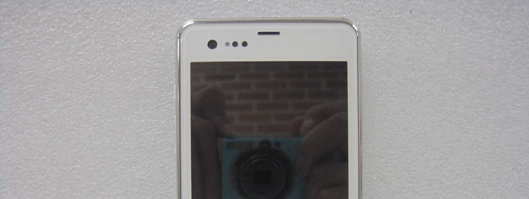
JYCCDMAPTL21
Aug 29, 2012GSM/WCDMA/CDMA Phone with Bluetooth/WLAN/NFC
Equipment Class
DSS - Part 15 Spread Spectrum Transmitter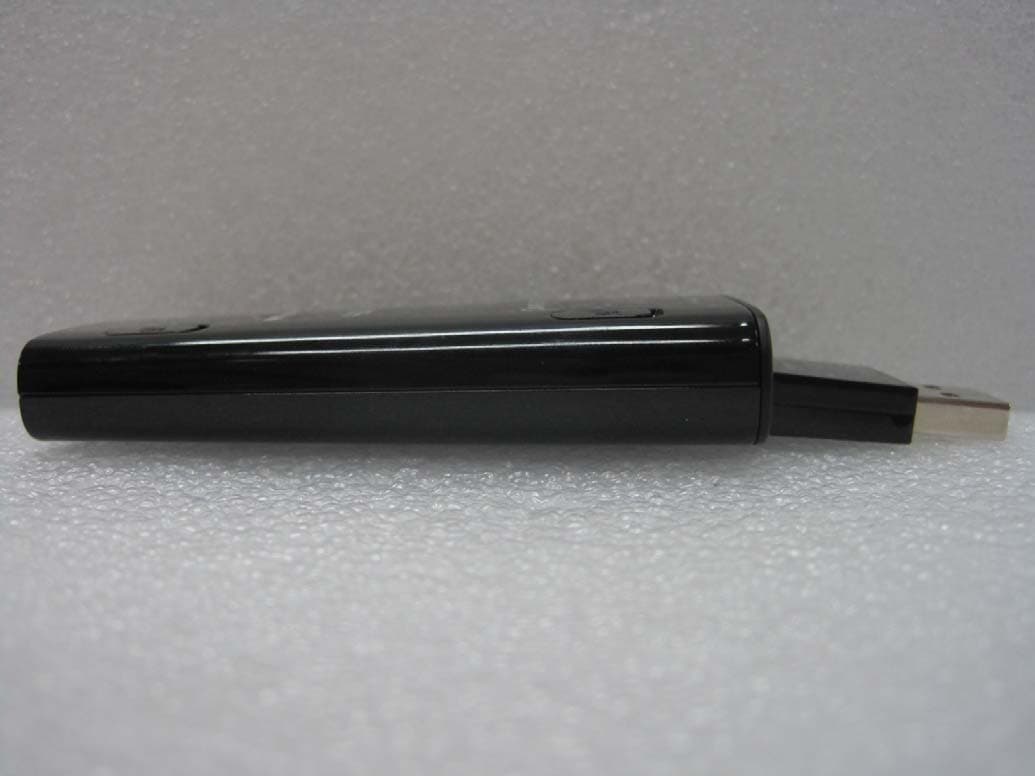
JYCSPARKLE
Aug 21, 2012CDMA/GSM/EDGE/WCDMA/LTE USB Data Dongle
Equipment Class
PCB - PCS Licensed Transmitter