K68ND241BLow Frequency Drill Location Device
Radiodetection Ltd
Click to zoom
Application Details
- Equipment Class
- DCD - Part 15 Low Power Transmitter Below 1705 kHz
- Date of Grant
- Jun 21, 2001
- Application Purpose
- Original Equipment
- Date of Application
- Jun 21, 2001
- Equipment Note
- Low Frequency Drill Location Device
- Frequency Range
- 0.03360000 - 0.03360000
- Company
- Radiodetection Ltd
- Country
- United Kingdom
Documents & Files
Document Text
Text extracted from the exhibit documents filed with the FCC. Open a document above to read the original.
Users Manual
DRILLTRACK USER MANUAL Revision 1 05.2001 I Foreword It is important that you read this user guide before operating your Radiodetection DrillTrack G2 system. This manual and all its contents are subject to change. Radiodetection products are under continuous development and are subject to change. Radiodetection Limited reserves the right to modify the product without notice. Some product changes may have taken place after this user guide was published. Contact your local Radiodetection dealer for the latest information on Radiodetection DrillTrack G2. Copyright © by RADIODETECTION TRENCHLESS PRODUCTS, a division of RADIODETECTION LTD. All rights reserved. The DrillTrack G2 system is covered by the following Patents: US 5,917,325; US6,107,801; GB2,330,204; EP 0,815,472; and other Patents pending IMPORTANT NOTICE Radiodetection makes every effort to ensure that all technical information, statements and recommendations about Radiodetection Trenchless products are based on information believed to be reliable, but the accuracy or completeness thereof is not guaranteed. In no event shall Radiodetection be liable for any loss, inconvenience, damage or problems caused through use of the equipment. Before utilizing the product, the user should determine the suitability of the product for its intended use. The user assumes all risks and liability whatsoever in connection with such use. COMPLIANCE STATEMENT When used in accordance with the user manual, relevant parts of this product comply with ‘The Radio Equipment and Telecommunications Terminal Equipment Directive’ (1999/5/EC) and/or EMC Directive (89/336/EEC) for use in a residential, commercial and light industry environment, as required. As appropriate, this equipment complies with the following:- FCC Part 90 FCC Part 15 EN 300 220-3 EN 300 330 EN 301 489-3 Appropriate radio transmissions from the equipment have been certified by the FCC. The following FCC IDs apply: E86DTR100: K68ND2415A; K68ND2415B; K68ND2415C; K68ND2415D This product must only be used with the antennas supplied with it. This product must not be connected to the mains supply, either directly or indirectly via an adaptor or battery eliminator. Such connection, use with other antenna or any changes, or modifications made to this product not expressly approved by Radiodetection Ltd could void the user's authority to operate the equipment. ll Note: Appropriate parts of this equipment have been tested and found to comply with the limits for a Class B digital device, pursuant to part 15 of the FCC Rules. These limits are designed to provide reasonable protection in a residential installation. This equipment generates, uses, and can radiate radio frequency energy and, if not installed and used in accordance with the instruction manual, may cause harmful interference to radio communications. However, there is no guarantee that interference will not occur in a particular installation. If this equipment does cause harmful interference to radio or television reception, which can be determined by turning the equipment off and on, the user is encouraged to correct the interference by one or more of the following measures: - reorient or relocate the receiving antenna. - Increase the separation between the equipment and receiver. - Connect the equipment into an outlet on a circuit different from that to which the receiver is connected. - Consult the dealer or an experienced radio/TV technician for help. All DrillTrack G2 units are weatherproof to NEMA 3R and IP54 All DrillTrack G2 units are shock and vibration tested to IEC68 All DrillTrack G2 units are manufactured according to the International Quality Norm ISO 9001 lII Table of Contents Foreword I Warnings and Safety PrecautionsIII (1) DrillTrack G2 System Overview Introduction1-1 Features of DrillTrack G2 Receiver and DataView1-2 (2) DataSonde The Radiodetection DataSondes2-1 Powersave Modes2-3 Overheat Warning2-3 DataSonde Magnetic Field2-4 Dual Frequency DataSonde change method2-4 (3) DrillTrack G2 Accessories DrillTrack G2 Tripod3-1 Calibration Jig3-1 Hard carry case3-2 Soft carry bag3-2 (4) DrillTrack G2 Function keys Receiver4-1 DataView4-2 (5) DrillTrack G2 Operating Instructions Before starting5-1 How to setup the DrillTrack G2 Receiver5-1 Calibration of the DrillTrack G2 Receiver5-6 Tilt angle compensation5-7 Borelogger5-8 Locating5-9 Steering5-12 High Temperature Alarm5-14 (6) DrillTrack G2 DataView DataView information6-1 Remote Steering6-1 (7) Tips and Tricks Troubleshooting Guide7-1 Angle conversion table7-3 Warranty Registration Card IV Warnings and Safety Precautions It is very important that Directional drilling operators note the operating procedures and safety precautions before operating the Radiodetection DrillTrack G2 system. -Priority must be given to local and national safety requirements all times. All other safety procedures should be followed. -All underground utilities MUST be located before starting the drilling operation. Contact your local Radiodetection dealer for pipe and cable locating equipment. -Serious injury and death can result if underground drilling equipment accidentally hits an underground utility. -Operators must wear protective safety clothing such as insulated boots, insulated gloves, high visibility safety vests, safety glasses and hard hats. The DrillTrack G2 system is not explosion-proof and is not approved for use in areas where hazardous gases may be present. The DrillTrack G2 system should never be used near flammable or explosive substances. Prior to the start of each drilling, the following actions must be taken: -An orientation working practice should be selected which is done in the DrillTrack G2 Receiver Setup Menu. Confirm that the DrillTrack G2 system is operating properly and check for an accurate location of the drillhead and accurate depth readings, tilt angle and roll position with the DataSonde inside the drillhead. During drilling, the depth readings and locate position wil…
Text truncated - open the document above for the full version.
Cover Letter(s)
ConfidentCase 18th May 2001 Page 1 of 3 Copyright © 2000 Radiodetection Ltd., Western Drive, Bristol, BS14 0AZ. Notice: Unauthorized disclosure or copying of this document or any part thereof is prohibited Radiodetection Limited Western Drive Bristol BS14 OAZ United Kingdom FCC ID: K68ND2415A, K68ND2415B, K68ND2415C, K68ND2415D - Application for Equipment Certification Request for Material to be Withheld from Public Inspection Introduction The Radiodetection Datasondes part numbers 10/ND2415-Y, 10/ND2415-P, 10/ND2415-G, 10/ND2415-OR are part of the Radiodetection Drilltrack system. The DrillTrack system is designed to provide the operator of a horizontal directional drill machine with information on the drillhead. Request for Material to be Withheld from Public Inspection For the reasons presented below, it is requested that the information detailed below is withheld from public inspection for a period of five years from its submission to the FCC by Radiodetection. Identification of Confidential Information Confidential treatment is being sought for the following information concerning all Radiodetection datasondes: - schematic circuit diagrams - manufacturing drawings - description of circuit functions and operation of G2 Datasondes A detailed list of confidential items is presented in Appendix 1 Reason for Submission The information is submitted in support of an application for FCC certification of the datasondes. Degree to which the Information is Confidential The information is confidential for commercial and financial reasons because Radiodetection has invested considerable design effort and expense in developing the datasonde and the system with which it works. ConfidentCase 18th May 2001 Page 2 of 3 Copyright © 2000 Radiodetection Ltd., Western Drive, Bristol, BS14 0AZ. Notice: Unauthorized disclosure or copying of this document or any part thereof is prohibited Degree to which the Information concerns a Service subject to Competition The datasonde is part of a system is designed to provide the operator of a horizontal directional drill machine with information on the drillhead. The market for products such as these is highly competitive. The system is sold to customers such as public utilities and telecommunications companies. The USA is Radiodetection’s largest market. Harm to Competitiveness Resulting from Disclosure of the Information Design and development costs make a significant contribution to the overall costs of our products and those of competitors. The products’ time-to-market depends to the time taken to complete the design phase. The disclosure of the information would give a competitor an unfair advantage by allowing it to reduce its design time and expenditure. Measures taken to Prevent Unauthorized Disclosure All Radiodetection designs are treated as ‘Company Confidential’. Design information is not released to third parties, other than those providing sub-contact production services to Radiodetection. Sub-contractors are subject to confidentiality agreements. Availability of the Information to the Public and Previous Disclosure to Third Parties The information submitted to the FCC is not available to the public or published by Radiodetection in its technical literature or handbooks. Products are sold only by Radiodetection and its own agents. There has been no previous disclosure to third parties, other than sub-contractors covered by confidentiality agreements. Justification for Period of Non-disclosure A non-disclosure period of five years is requested to ensure the any future disclosure of Radiodetection’s design will not take place until the datasonde and its design ideas are no longer of commercial value. For and on behalf of Radiodetection Limited, Norman Prior EMC Approval Engineer Direct Dial: +44 117 988 6220 Fax: +44 117 976 7775 E-mail: [email protected] ConfidentCase 18th May 2001 Page 3 of 3 Copyright © 2000 Radiodetection Ltd., Western Drive, Bristol, BS14 0AZ. Notice: Unauthorized disclosure or copying of this document or any part thereof is prohibited Appendix 1 List of Confidential Information Schematic Drawings Drawing No.DescriptionElectronic File 1) ND2415.ADS/DF – G2 Output PCBND2415-A-1.pdf & ND2415-A-2.pdf 2) ND2416.ADS/DF – G2 Micro PCBND2416-A-1.pdf & ND2416-A-2.pdf 3) RS1088.AROLL SENSOR TRACK BOARDRS1088-A-1G.jpg 4) RS1089.AROLL SENSOR SEGMANT BOARD RS1089-A-2A.jpg Manufacturing Drawings and specifications 5) NDND2415.V1G2 SONDE GENERAL ASSEMBLYND1415-V1.jpg 6) ND1327.W2RD385 HI POWERND1327-W2-SPEC.jpg 8) antenna schematicantenna schematic.doc 9)Circuit functions and OperationCircuit functions.doc 10) Hardware Block DiagramHardware Diagram.doc 11)Functional DiagramFunctional Diagram.doc
Cover Letter(s)
FCC Labelling Requirements and Information 23rd May 2001 Page 1 of 1 Copyright © 2000 Radiodetection Ltd., Western Drive, Bristol, BS14 0AZ. Notice: Unauthorized disclosure or copying of this document or any part thereof is prohibited Radiodetection Limited Western Drive Bristol BS14 OAZ United Kingdom FCC Labelling Requirements and Information American Telecommunications Certification Body, Inc. 6731 Whittier Avenue Suite C110 McLean, VA 22101 RE: FCC Labeling Requirements FCC ID: K68ND2415B The following label information is required by the FCC Rules and Regulations for certified devices. Also attached, please find marketing information required by the FCC Rules and Regulations. Thank you for your attention to these matters. For and on behalf of Radiodetection Limited, Norman Prior EMC Approval Engineer Direct Dial: +44 117 988 6220 Fax:+44 117 976 7775 E-mail:[email protected]
Cover Letter(s)
Letter of Agency 23rd May 2001 Page 1 of 1 Copyright © 2000 Radiodetection Ltd., Western Drive, Bristol, BS14 0AZ. Notice: Unauthorized disclosure or copying of this document or any part thereof is prohibited Radiodetection Limited Western Drive Bristol BS14 OAZ United Kingdom American Telecommunications Certification Body, Inc. 6731 Whittier Avenue Suite C110 McLean, VA 22101 To Whom It May Concern: Please be advised that Radiodetection Ltd. authorizes SGS-IEA to act on our behalf, until otherwise notified, for applications submitted to American Telecommunications Certification Body, Inc. (ATCB). We certify that we are not subject to denial of federal benefits, that includes FCC benefits, pursuant to Section 5301 of the Anti-Drug Abuse ACT of 1988, U.S.C. 862. Further, no party, as defined in 47 CFR 1.2002(b), to the application is subject to denial of federal benefits, that includes FCC benefits. Thank you for your attention to this matter. For and on behalf of Radiodetection Limited, Norman Prior EMC Approval Engineer Direct Dial: +44 117 988 6220 Fax:+44 117 976 7775 E-mail:[email protected]
Operational Description
Circuit Functions and Operation of G2 Datasondes 1. Applicability This document applies to the following products:- Datasonde type 10/ND2415-PFCC ID K68ND2415B 2. Circuit functions A block diagram of the electronic hardware is shown in figure 1. The circuit functions are shown in Figure 2. The product is powered by two1.5V internal batteries. A switched mode power supply converts the battery voltage to a +5V supply for the electronic parts. Various sensors, namely a battery voltage sensor, roll sensor, tilt sensor, and temperature sensor feed the outputs into a microprocessor. A 4.194304 MHz oscillator is used to drive the roll sensor. The transmitted frequency is also derived from this oscillator, after being divided down by a divider and the antenna driver. The microprocessor is driven from a 4.608 MHz crystal oscillator. This data is then Manchester encoded at 150 Hz bit. The antenna driver feeds the transmitted signal to the antenna. The transmitted signal is a fundamental frequency of 8192 Hz or 32768 Hz depending on operating mode, 100% amplitude modulated by the encoded data. The datasonde is able to transmit at either 8192 Hz or 32768 Hz. The actual frequency transmitted can be toggled between the two frequencies by rotating the product through a particular sequence of orientations. The external metal battery housing is connected to the battery –ve terminal that is also connected to the ground planes of all the PCBs. The ground simply acts as a reference point and as an earth return. The antenna used is a ferrite cored coil antenna with a driven primary and a tuned secondary. The secondary is self-tuned to approximately 33 kHz. The antenna arrangement is shown in figure 3. Figures 1, 2, and 3 are contained in the electronic files as follows: Figure 1Hardware Diagram.doc Figure 2Y-P Functional Diagram.doc Figure 3antenna schematic.doc.
Operational Description
P Overview 18th May 2001 Page 1 of 3 Copyright © 2000 Radiodetection Ltd., Western Drive, Bristol, BS14 0AZ. Notice: Unauthorized disclosure or copying of this document or any part thereof is prohibited Radiodetection Limited Western Drive Bristol BS14 OAZ United Kingdom FCC ID: K68ND2415B - Application for Equipment Certification Overview of Submission Introduction This submission relates to the following products: ProductRadiodetection Part NumberFCC ID Datasonde10/ND2415-PK68ND2415B This product forms part of the Radiodetection Drilltrack system which is described in the User Manual (electronic file G2 User Manual.pdf). The DrillTrack system is designed to provide the operator of a horizontal directional drill machine with information on the drillhead. Datasonde type 10/ND2415-P is part of a family of similar datasondes. Applications for equipment certification have also been made for the following datasondes types: Datasonde10/ND2415-YK68ND2415A Datasonde10/ND2415-GK68ND2415C Datasonde10/ND2415-ORK68ND2415D These products differ in that they transmit at differing frequencies and/or power levels. The above products are manufactured from the same hardware and software except:- a) The crystal oscillator fitted to PCB ND2415/D has a different operating frequency for products 10/ND2415-Y and 10/ND2415-P than types 10/ND2415-G and 10/ND2415-OR. b) The links on PCB ND2416/D are different for each product. c) a different metal housing is used for products 10/ND2415-Y and 10/ND2415-G than types 10/ND2415-P and 10/ND2415-OR. For this reason, except for different housing drawings (ND2415.N1 and ND2415.N2), all manufacturing drawings are the same for all four products. Request for Material to be Withheld from Public Inspection This is contained in electronic file ConfidentCase.doc P Overview 18th May 2001 Page 2 of 3 Copyright © 2000 Radiodetection Ltd., Western Drive, Bristol, BS14 0AZ. Notice: Unauthorized disclosure or copying of this document or any part thereof is prohibited ID Label/Location Information The FCC ID is permanently pin stamped on the product as shown on drawing ND2415.V1 (electronic file ND2415-V1.jpg) The label required by 47CFR15.19(3) is shown in electronic file label.jpg. This is an undersurface silkscreened plastic label that is affixed to the product by a permanent adhesive. The location of the label is shown on drawing ND2415.V1 (electronic file ND2415-V1.jpg). Block Diagrams A block diagram of the hardware is shown in electronic file - Hardware Diagram.jpg. A functional block diagram is shown in electronic file – Y-P Functional Diagram.jpg. Schematics Circuit schematics are as follows: Part NumberDrawing NumberElectronic file 09/ND2415/DND2415.A sheets 1 & 2ND2415-A-1.pdf & ND2415-A-2.pdf 09/ND2416/DND2416.A sheets 1 & 2ND2416-A-1.pdf & ND2416-A-2.pdf 09/1088/DRS1088.ARS1088-A-1G.jpg 09/1089/DRS1089.ARS1089-A-2A.jpg Antenna A schematic of the antenna is shown in electronic file – antenna schematic.doc. The specification drawing for the antenna windings is shown in electronic file ND1327- W2-SPEC.jpg. The antenna is self tuned when operated at 33 kHz nominal, but is tuned by a capacitor, which is switched in circuit, when operated at 8 kHz nominal. User Manual The user manual is contained in electronic file – G2 User Manual.pdf. This User Manual covers the complete Drilltrack System that includes the datasonde. Note datasonde type 10/ND2415-P is referred to as a Long Range Dual Frequency Datasonde (LDF Purple). P Overview 18th May 2001 Page 3 of 3 Copyright © 2000 Radiodetection Ltd., Western Drive, Bristol, BS14 0AZ. Notice: Unauthorized disclosure or copying of this document or any part thereof is prohibited Operational Description The circuit functions and operational description is contain in electronic file – Y-P Circuit functions.doc. For and on behalf of Radiodetection Limited, Norman Prior EMC Approval Engineer Direct Dial: +44 117 988 6220 Fax:+44 117 976 7775 E-mail:[email protected]
Test Report
Page 1 of 12 Member of the SGS Group (Société Générale de Surveillance) Registered in England No. 1193985. Registered Office: SGS House, 217-221 London Road, Camberley, Surrey, GU15 3EY SGS United Kingdom Ltd. International Electrical Approvals αβχ South Industrial Estate Bowburn Co. Durham DH6 5AD United Kingdom Telephone: +44 (0) 191 377 2000 Fax: +44 (0) 191 377 2020 [email protected] Electromagnetic Compatibility Test Report Test of: Datasonde 8 kHz/32.768 kHz High power Model Number: 10/ND2415-P Applicant: Radiodetection Ltd Test Type: Compliance Test Specification: FCC CFR47, part 15.209 for Intentional Radiators. SGS Serial Number: DUR22909/EMC/ST/01/C Date of Receipt: 5 th March 2001 Date of Test(s): 19 th March 2001 – 22 nd March 2001 Date of Issue: 20 th April 2001 Issue Number: 2 Test Engineer Authorised Signatory S. Thompson F. Huggins / A. Reynard / M. Harvey αβχ TEST REPORT Page 2 of 12 Issue Date: 20 th April 2001 SGS Serial Number: DUR22909/EMC/ST/01/C Issue Number: 2 CONTENTS Page Number 1. Client Information...................................................................................................... 3 2. Details Of Test Laboratory.......................................................................................... 3 3. Equipment Under Test (EUT)....................................................................................... 4 3.1 Identification Of EUT .............................................................................................................................4 4. Test Specification, Methods and Procedures.................................................................. 4 4.1 Test Specification(s) ..............................................................................................................................4 4.2 Purpose Of Test ....................................................................................................................................4 4.3 Methods and Procedures ........................................................................................................................5 5. Deviations or Exclusions from the Test Specifications ..................................................... 6 6. Operation of the EUT During Testing / Configuration and Peripherals................................. 7 6.1 Operation of EUT during testing. .............................................................................................................7 6.2 Configuration and Peripherals..................................................................................................................7 7. Test Results ............................................................................................................. 7 7.1 General Comments ................................................................................................................................7 7.2 Modifications Made to the EUT ...............................................................................................................7 7.3 Summary of Test Results .......................................................................................................................8 7.4 Transmitter Radiated Emissions <30 MHz - Intentional Radiator ...................................9 7.5 Transmitter Radiated Emissions 30 MHz – 1 GHz - Intentional Radiator........................ 11 αβχ TEST REPORT Page 3 of 12 Issue Date: 20 th April 2001 SGS Serial Number: DUR22909/EMC/ST/01/C Issue Number: 2 1. Client Information Company Name: Radiodetection Ltd Address: Western Drive Bristol BS14 0AZ Contact Person: Norman Prior Telephone: 0117 976 7776 Facsimile: 0117 976 7775 2. Details Of Test Laboratory Company Name: SGS UK LTD. Address: South Industrial Estate Bowburn Co. Durham DH6 5AD Contact Persons: Mr Alan Reynard Telephone: +44 191 377 2000 Facsimile: +44 191 377 2020 αβχ TEST REPORT Page 4 of 12 Issue Date: 20 th April 2001 SGS Serial Number: DUR22909/EMC/ST/01/C Issue Number: 2 3. Equipment Under Test (EUT) 3.1 Identification Of EUT Model Number: 10/ND2415-P Unique Identifier: IP00003 FCC ID: K68ND2415B Description of EUT: The EUT is a Datasonde Fundamental (Carrier) Frequency 8kHz or 33.6 kHz Internal Clock Frequencies: Highest frequency used is 4.608 MHz Supply Voltage: 3V DC using 2x ‘C’ size batteries Classification: Intentional radiator incorporating digital device Environment Class: Class B Ports present: None – Battery Powered Accessories Supplied: G2 DrillTrack System * * This was used solely to ensure the datasonde was operating correctly and to change the operating frequency of the datasonde. This was not in the test area whilst the tests were conducted. 4. Test Specification, Methods and Procedures 4.1 Test Specification(s) Specification(s) Title FCC CFR 47 part 15.209 Code Of Federal Regulations ANSI C63.4 : 1992 American National Standard for Methods of Measurement of Radio-Noise Emissions from Low-Voltage Electrical and Electronic Equipment in the Range of 9kHz to 40GHz. 4.2 Purpose Of Test To perform the relevant tests and assess the product for compliance with the above specification. αβχ TEST REPORT Page 5 of 12 Issue Date: 20 th April 2001 SGS Serial Number: DUR22909/EMC/ST/01/C Issue Number: 2 4.3 Methods and Procedures The standards listed on the previous page refer to the following tests: CFR 47 Clause Test 15.209 Radiated Emissions (Intentional Radiator) αβχ TEST REPORT Page 6 of 12 Issue Date: 20 th April 2001 SGS Serial Number: DUR22909/EMC/ST/01/C Issue Number: 2 5. Deviations or Exclusions from the Test Specifications There were no deviations from the test specifications. The scope of the inspection is limited to what is specified in the clients instructions and does not include any other checks or tests such as the electrical (electronic) control systems ability to cope with the implications of the dates falling on, before or after “January 2000”. αβχ TEST REPORT Page 7 of 12 Issue Date: 20 th …
Text truncated - open the document above for the full version.
Test Setup Photos
αβχ TEST REPORT Page 10 of 12 Issue Date: 20 th April 2001 SGS Serial Number: DUR22909/EMC/ST/01/C Issue Number: 2 Radiated Emissions Test Configuration Radiated Emissions Environmental Conditions Power Supply 3V DC using x2 ‘C’ size batteries Temperature 8°C Relative Humidity 49% Barometric Pressure 1011mb Radiated Emissions Measurement Uncertainties Frequency ± 200kHz Amplitude ± 4.6dB The uncertainties stated are calculated in accordance with the requirements of UKAS with a confidence level of 95%. Test Equipment Used Equipment Type Model Number Last Calibration Date Calibration Interval Active loop antenna EMCO 6152 7/8/98 3 Years Spectrum Analyser HP 8563E 10/5/00 1 Year αβχ TEST REPORT Page 11 of 12 Issue Date: 20 th April 2001 SGS Serial Number: DUR22909/EMC/ST/01/C Issue Number: 2 7.5 Transmitter Radiated Emissions 30 MHz – 1 GHz - Intentional Radiator CFR Clause 15.209 Frequency Range 30 MHz – 1 GHz Operating Mode The EUT was operating whilst the transmitter frequency was set at 33 kHz and repeated when set to 8 kHz. Test Results Transmitter at 33 kHz Frequency (MHz) 3m Peak Measurement (dBμ μμ μV/m) Limit at 3m (dBμ μμ μV/m) 110 17.13 43.52 262 19 46.00 267.35 18.5 46.00 271.93 18.92 46.00 276.57 19.12 46.00 850* 29.42 46.00 Transmitter at 8 kHz Frequency (MHz) 3m Peak Measurement (dBμ μμ μV/m) Limit (dBμ μμ μV/m) 114.67 24.26 43.52 258.05 19.68 46.00 267.3 17.97 46.00 271.93 19.35 46.00 600* 26.14 46.00 850* 29.42 46.00 * Noise floor figures of test equipment. Test Method As per ANSI C63.4 : 1992 Frequency Range tested = 30 MHz to 1 GHz (as per sec 15.33 (a)(4) ). Measurement Detector Details: Peak, 300Hz bandwidth at frequencies below 150 kHz, 10 kHz at frequencies above 150 kHz. Measurements were performed at 3m. αβχ TEST REPORT Page 12 of 12 Issue Date: 20 th April 2001 SGS Serial Number: DUR22909/EMC/ST/01/C Issue Number: 2 Radiated Emissions Test Configuration Radiated Emissions Environmental Conditions Power Supply 3V DC using 2x ‘C’ size batteries Temperature 14°C Relative Humidity 32% Barometric Pressure 989mb Radiated Emissions Measurement Uncertainties Frequency ± 200kHz Amplitude ± 4.6dB The uncertainties stated are calculated in accordance with the requirements of UKAS with a confidence level of 95%. Test Equipment Used Equipment Type Model Number Last Calibration Date Calibration Interval Biconilog antenna EMCO 3142 22/6/99 2 Years Spectrum Analyser HP 8563E 10/5/00 1 Year
Contact Information
Applicant
Andrew Brown(Principal Engineer)
Technical Contact
SGS UK Ltd.Dave Spence
[email protected]+44 191 377 2000
South Industrial Estate · Co. Durham · United Kingdom
Test Firm
SGS United Kingdom Ltd.Stephen Thompson
Technical Specifications
| # | Rule Parts | Frequency Range | Power Output |
|---|---|---|---|
| 1 | 15C | 0.0336 MHz - 0.0336 MHz | - |
Other Applications from Radiodetection Ltd
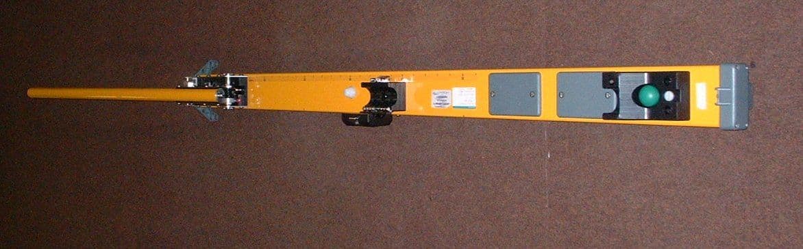
K68AA2614
Nov 19, 200220ft Vector Bar type 10/AA 2614
Equipment Class
DSC - Part 15 Security/Remote Control Transmitter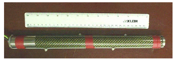
K68ND2585
Jul 08, 200210/ND2585 Wireline DataSonde
Equipment Class
DCD - Part 15 Low Power Transmitter Below 1705 kHz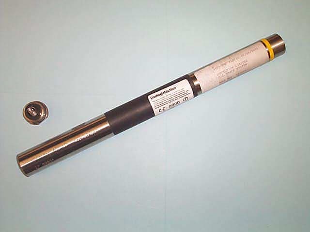
K68ND241A
Jun 21, 2001Low Frequency Drill Location Device
Equipment Class
DCD - Part 15 Low Power Transmitter Below 1705 kHz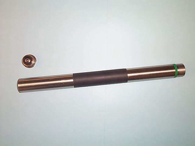
K68ND241C
Jun 21, 2001Low Frequency Drill Location Device
Equipment Class
DCD - Part 15 Low Power Transmitter Below 1705 kHz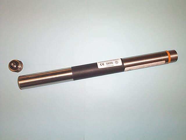
K68ND241D
Jun 21, 2001Low Frequency Drill Location Device
Equipment Class
DCD - Part 15 Low Power Transmitter Below 1705 kHz