K68ND258510/ND2585 Wireline DataSonde
Radiodetection Ltd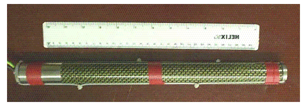
Click to zoom
Application Details
- Equipment Class
- DCD - Part 15 Low Power Transmitter Below 1705 kHz
- Date of Grant
- Jul 08, 2002
- Application Purpose
- Original Equipment
- Date of Application
- Jul 08, 2002
- Equipment Note
- 10/ND2585 Wireline DataSonde
- Frequency Range
- 0.03368600 - 0.03409700
- Company
- Radiodetection Ltd
- Country
- United Kingdom
Documents & Files
Document Text
Text extracted from the exhibit documents filed with the FCC. Open a document above to read the original.
Users Manual
DRILLTRACK USER MANUAL Revision 3 10.2001 www.radiodetection.com I Foreword It is important that you read this user manual before operating your Radiodetection DrillTrack system. This manual and all its contents are subject to change. Radiodetection products are under continuous development and are subject to change. Radiodetection Limited reserves the right to modify the product without notice. Some product changes may have taken place after this user manual was published. Contact your local Radiodetection dealer for the latest information on Radiodetection DrillTrack Copyright © by RADIODETECTION TRENCHLESS PRODUCTS, a division of RADIODETECTION LTD. All rights reserved. The DrillTrack system is covered by the following Patents: US 5,917,325; US6,107,801; GB2,330,204; EP 0,815,472; and other Patents pending IMPORTANT NOTICE Radiodetection makes every effort to ensure that all technical information, statements and recommendations about Radiodetection Trenchless products are based on information believed to be reliable, but the accuracy or completeness thereof is not guaranteed. In no event shall Radiodetection be liable for any loss, inconvenience, damage or problems caused through use of the equipment. Before utilizing the product, the user should determine the suitability of the product for its intended use. The user assumes all risks and liability whatsoever in connection with such use. COMPLIANCE STATEMENT When used in accordance with the user manual, relevant parts of this product comply with ‘The Essential Requirements of the Radio Equipment and Telecommunications Terminal Equipment Directive’ (1999/5/EC) and/or EMC Directive (89/336/EEC) for use in a residential, commercial and light industry environment, as required. As appropriate, this equipment complies with the following:- FCC Part 90 FCC Part 15 EN 300 220-3 EN 300 330 EN 301 489-3 Appropriate radio transmissions from the equipment have been certified by the FCC. The following FCC IDs apply: E86DTR100: K68ND2415A; K68ND2415B; K68ND2415C; K68ND2415D This product must only be used with the antennas supplied with it. This product must not be connected to the mains supply, either directly or indirectly via an adapter or battery eliminator. Such connection, use with other antenna or any changes, or modifications made to this product not expressly approved by Radiodetection Ltd could void the user's authority to operate the equipment. ll Note: Appropriate parts of this equipment have been tested and found to comply with the limits for a Class B digital device, pursuant to part 15 of the FCC Rules. These limits are designed to provide reasonable protection in a residential installation. This equipment generates, uses, and can radiate radio frequency energy and, if not installed and used in accordance with the user manual, may cause harmful interference to radio communications. However, there is no guarantee that interference will not occur in a particular installation. If this equipment does cause interference to radio or television reception, which can be determined by turning the equipment off and on, the user is encouraged to correct the interference by one or more of the following measures: - Reorient or relocate the receiving antenna. - Increase the separation between the equipment and receiver. - Consult your Radiodetection office for help. All DrillTrack units are weatherproof to NEMA 3R and IP54 All DrillTrack units are shock and vibration tested to IEC68 All DrillTrack units are manufactured according to the International Quality Norm ISO 9001 lII Table of Contents Foreword I Warnings and Safety PrecautionsIV (1) DrillTrack System Overview Receiver1-1 DataView1-2 Tripod1-2 DataSonde1-3 (2) DrillTrack Function keys Receiver2-1 DataView2-2 (3) DrillTrack Operating Instructions Before starting3-1 Setup the DrillTrack Receiver3-1 Calibration of the DrillTrack Receiver3-4 DrillTrack Receiver operation3-5 Steering3-8 Tilt angle compensation3-10 DrillTrack DataView operation3-11 Remote Steering3-11 DataSonde Power Save modes3-14 Dual Frequency operation3-14 DataSonde Temperature Alarm3-15 (4) DrillTrack Borelogger4-1 (5) Tips and Tricks Troubleshooting Guide5-1 Angle conversion table5-3 (6) Technical Specifications Receiver6-1 DataView6-2 Borelogger6-2 DataSondes6-3 Warranty Registration Card IV Warnings and Safety Precautions It is very important that Directional drilling operators note the operating procedures and safety precautions before operating the Radiodetection DrillTrack system. -Priority must be given to local and national safety requirements all times. All other safety procedures should be followed. -All underground utilities MUST be located before starting the drilling operation. Contact your local Radiodetection dealer for pipe and cable locating equipment. -Serious injury and death can result if underground drilling equipment accidentally hits an underground utility. -Operators must wear protective safety clothing such as insulated boots, insulated gloves, high visibility safety vests, safety glasses and hard hats. The DrillTrack system is not explosion-proof and is not approved for use in areas where hazardous gases may be present. The DrillTrack system should never be used near flammable or explosive substances. Prior to the start of each drilling, the following actions must be taken: -An orientation working practice should be selected which is done in the Receiver Setup Menu. (see page 3-1) Confirm that the DrillTrack system is operating properly and check for an accurate location of the drillhead and accurate depth readings, Tilt angle and Roll position with the DataSonde inside the drillhead. During drilling, the depth readings and locate position will not be accurate unless: - A consistent orientation working practice will be maintained. (changing from facing the Drilling machine to working with one’s back to the Drilling machine or visa versa could result in both a mis-locate position/depth error). This eff…
Text truncated - open the document above for the full version.
Cover Letter(s)
Page 1 of 3 Certificate No FM12608 Radiodetection Limited Registered office Western Drive Bristol BS14 0AZ, UK Tel +44 (0) 117 9767776 Fax +44 (0) 117 9767775 http://www.radiodetection.com 10 June 2002 FCC ID: K68ND2585 Application for Equipment Certification Request for Material to be Withheld from Public Inspection Introduction The Radiodetection Wireline DataSonde (part number ND2585 is part of the Radiodetection Drilltrack system. The DrillTrack system is designed to provide the operator of a horizontal directional drill machine with information on the drillhead. Request for Material to be Withheld from Public Inspection For the reasons presented below, it is requested that the information detailed be withheld from public inspection for a period of five years from its submission to the FCC by Radiodetection. Identification of Confidential Information Confidential treatment is being sought for the following information concerning the Radiodetection ND2585 DataSonde: - schematic circuit diagrams - internal photographs A detailed list of confidential items is presented in Appendix 1 Reason for Submission The information is submitted in support of an application for FCC certification of the ND2585 DataSonde. Degree to which the Information is Confidential The information is confidential for commercial and financial reasons because Radiodetection has invested considerable design effort and expense in developing the DataSonde and the system with which it works. Degree to which the Information concerns a Service subject to Competition The DataSonde is part of a system is designed to provide the operator of a horizontal directional drill machine with information on the drillhead. The market for products such as these is highly competitive. The system is sold to customers such as public Page 2 of 3 Certificate No FM12608 utilities and telecommunications companies. The USA is Radiodetection’s largest market. Harm to Competitiveness Resulting from Disc losure of the Information Design and development costs make a significant contribution to the overall costs of our products and those of competitors. The products’ time-to-market depends to the time taken to complete the design phase. The disclosure of the information would give a competitor an unfair advantage by allowing it to reduce its design time and expenditure. Measures taken to Prevent Unauthorized Disclosure All Radiodetection designs are treated as ‘Company Confidential’. Design information is not released to third parties, other than those providing sub-contact production services to Radiodetection. Sub-contractors are subject to confidentiality agreements. Availability of the Information to the Public and Previous Disclosure to Third Parties The information submitted to the FCC is not available to the public or published by Radiodetection in its technical literature or handbooks. Products are sold only by Radiodetection and its own agents. There has been no previous disclosure to third parties, other than sub-contractors covered by confidentiality agreements. Justification for Period of Non-disclosure A non-disclosure period of five years is requested to ensure the any future disclosure of Radiodetection’s design will not take place until the DataSonde and its design ideas are no longer of commercial value. For and on behalf of Radiodetection Limited, Keith Jones Keith Jones Approvals Engineer Page 3 of 3 Certificate No FM12608 Appendix 1 List of Confidential Information Drawing ND 2545-flexy ND 2445-layout ND 2545-output ND 2545-psu ND 2546-filter ND 2546-flexy ND 2546-layout ND 2546-power blocks ND 2546-processor ND 2546-rx ND 2546-sensors ND 2545.D Output PCB parts list ND 2546.D Processor PCB parts list Block diagram of DataSonde wireline system
Cover Letter(s)
TRL 51F046 iss01 Radiodetection Limited Registered office Western Drive Bristol BS14 0AZ, UK Tel +44 (0) 117 9767776 Fax +44 (0) 117 9767775 http://www.radiodetection.com FCC Warning Statements 10 June 2002 TRL Compliance Services Ltd Long Green Forthampton Gloucester GL19 4QH UK RE: Warning Statements FCC ID: K68ND2585 There are a number of warning statements applicable to the Wireline DataSonde. As the general operation of the Wireline DataSonde is underground, the warning statements will be contained in the user manual 90_UG050OUS (refer to user manual supplied). A copy of any further warnings that may be applicable when updating the user manual will be passed to TRL TCB as soon as possible. Note: Its operation is identical to that of the already approved version with the exception of the hard- wiring. Thank you for your co operation on these matters. Y ours faithfully Keith Jones Keith Jones Radiodetection Ltd.
External Photos
EXTERNAL PHOTOGRAPH DataSonde
ID Label/Location Info
PDFMAILER.COM Print and send PDF files as Emails with any application, ad-sponsored and free of charge www.pdfmailer.com
Internal Photos
Photograph 1 External view Photograph 2 TX PCB Track Side Photograph 3 TX PCB Component Side
Operational Description
1 Certificate No FM12608 Radiodetection Limited Registered office Western Drive Bristol BS14 0AZ, UK Tel +44 (0) 117 9767776 Fax +44 (0) 117 9767775 http://www.radiodetection.com Operational/Product Description/Technical Description Introduction The purpose of the system is to enable an Underground Horizontal Boring Machine to be used in a controlled manner, monitor its progress and provide orientation information so that steering corrections can be made. It is intended to be compatible for use with the DrillTrack G2 Receiver (ND2422) and provides a design modification of the DrillTrack G2 DataView. Product Details Product Description The System comprises a cable powered DataSonde transmitter, Surface Control unit and a DataView remote display unit. The sensor data from the DataSonde is modulated on to an AC carrier signal, and output by means of an EM signal propagated into free space and by an AC current flowing in the power supplies. The bore rods and a cable running inside them form the power supply circuit, this circuit is completed by connecting to the Surface Control Box at the surface. A DrillTrack G2 Receiver (11/ND2422), not forming part of the system for approval purposes, can also be used to pinpoint the spatial position of the DataSonde underground and decode orientation sensor data uses the field shape characteristics of the modulated output EM signal from the DataSonde. The DataSonde output is an AC modulated carrier signal at 33725 Hz. A solenoid antenna forms the output EM and current signals, the AC current is applied to the power supply circuit by a secondary winding on the antenna using the incoming power supply cable. 2 Certificate No FM12608 The Surface Control unit is powered from an external 12-24V DC power supply. This unit is connected to the DataView to provide power and serial data communications between units and provides a regulated 22-28V DC supply to the DataSonde. Using the power supply circuit formed by the internal cable and bore rods the modulated AC current, impressed by the DataSonde, is recovered and decoded by electrical circuits and a Microcontroller. The data is error checked and conditioned by software processes and output serially to the DataView. The DataView unit provides the primary user interfaces, with a custom LCD display, LED array and audio sounder. The unit is powered by the Surface Control unit and displays data from both the Surface Control unit, via the serial digital interface, and a DrillTrack Receiver, via a low power UHF radio link. To manage system configurations where a DrillTrack Receiver or Cable powered DataSonde may not used, there is bi-directional data flow between the Surface Control unit and DataView and software processes are used to automatically manage each configuration. As the bore progresses the power supply circuit is extended by butt splicing sections of cable inside each rod. Typically each rod is 3m in length and bores extend to between 30 and 300m depending on the technical requirements of the bore. Product operation Each unit is portable and battery powered so that it can be simply fitted and removed from different boring machines as required. The DataView and Surface Control Box are magnetically attached to the machine metalwork and each other. They are connected to each other using a supplied interconnection cable and to a customer-supplied external 12-24 V DC battery. The DataSonde is fitted into a custom designed head assembly manufactured by the boring machine manufacturer. The DataSonde power supply cable is output from the machine using a manufacturer supplied slip rung assembly and connected to the Surface Control unit using the supplied output lead. Correct operation of the software within the Surface Control unit is indicated by a green coloured LED on the front panel. Pressing the push button on the front panel applies the 22-28V output voltage to the DataSonde power supply circuit, the circuit impedance and correct operation of the DataSonde are indicated ion the front panel by 3 LED’s. A green LED (OK) indicates that data is being recovered correctly, either of two red LED’s indicate a short or open circuit fault condition, which can be used by the operator to diagnose and rectify the fault. 3 Certificate No FM12608 When the DataSonde has been powered up it transmits the EM location signal for the DrillTrack Receiver, if used, and circulates the AC current in the power supply circuit. When the Surface Control unit has correctly recovered this data it is then transmitted to the DataView where it is decoded and displayed. The Surface Control unit and DataSonde act together to provide remote voltage sensing of the output voltage at the DataSonde, this compensates for any voltage drop through the cable and rod circuit. Software within the DataSonde monitors the DC voltage and sends this back as part of the data stream, the Surface Control unit software extracts this data and uses it to adjust the applied output voltage in 3 equal steps from 22.6 to 28.6 V. The DataView unit can be operated on its own, from its own battery pack, or connected to a Surface Control unit. In either operating configuration the unit displays DataSonde and Locate data on a custom LCD, a series of LED’s and a sounder as appropriate. An LCD backlight can be turned on to improve low light vis ibility. When connected to a Surface Control box, one pair of batteries must be removed and an interconnection cable and connector assembly fitted in replacement of the battery cover, mechanical interlocking prevents the batteries being fitted. The connector assembly has 4x spring loaded ball pin connections which mate to corresponding contacts within the DataView. When assembled these connections enable bi-directional RS232 data transmission between units, the DataView is powered from the Surface Control unit. Technical Description DataSonde Wireline Output PCB 09/ND2545/D The cable input from the power supply circuit is connected throu…
Text truncated - open the document above for the full version.
Test Report
TRL C OMPLIANCE S ERVICES L TD EMC DIVISION LONG GREEN FORTHAMPTON GLOUCESTER GL19 4QH UNITED KINGDOM TELEPHONE +44 (0)1684 833818 FAX +44 (0)1684 833858 E- MAIL [email protected] www.trlcompliance.com 0728 TEST REPORT NO:RU1014/3804 COPY NO:2 ISSUE NO:1 FCC ID:K68ND2585 REPORT ON THE CERTIFICATION TESTING OF A Radiodetection Ltd. Wireline DataSonde WITH RESPECT TO THE FCC RULES CFR 47, PART 15.209 INTENTIONAL RADIATOR SPECIFICATION TEST DATE: 21 st - 22 nd May 2002 TESTED BY:J CHARTERS APPROVED BY:P GREEN PRINCIPAL ENGINEER DATE:8 th July 2002 Distribution: Copy Nos:1.Radiodetection Ltd. 2.FCC EVALUATION LABORATORIES 3.TRL EMC THIS DOCUMENT MAY BE REPRODUCED ONLY IN ITS ENTIRETY AND WITHOUT CHANGE RF335 iss02RU1014/3804Page 2 of 19 CONTENTS PAGE CERTIFICATE OF CONFORMITY & COMPLIANCE3 APPLICANT’S SUMMARY4 EQUIPMENT TEST CONDITIONS5 TESTS REQUIRED6 SAMPLE CALCULATIONS6 TEST RESULTS7-8 ANNEX PHOTOGRAPHSA PHOTOGRAPH No. 1: Test setup PHOTOGRAPH No. 2: Transmitter front view PHOTOGRAPH No. 3: Transmitter PCB track side PHOTOGRAPH No. 4: Transmitter PCB component side APPLICANT’S SUBMISSION OF DOCUMENTATION LISTB BAND OCCUPANCY PLOTC Notes: 1.Component failure during testYES NO [ ] [X] 2.If Yes, details of failure: 3.The facilities used for the testing of the product contained in this report are FCC Listed. 4.The contents of the attached applicants declarations and other supplied information are not covered by the scope of this laboratory’s UKAS or FCC accreditations’ and is provided in good faith. RF335 iss02RU1014/3804Page 3 of 19 CERTIFICATE OF CONFORMITY & COMPLIANCE FCC IDENTITY:K68ND2585 PURPOSE OF TEST:Certification TEST SPECIFICATION:FCC RULES CFR 47, Part 15.209 TEST RESULT:Compliant to Specification EQUIPMENT UNDER TEST:Wireline DataSonde EQUIPMENT SERIAL No:Engineering sample ITU EMISSION CODE:4K80A3D EQUIPMENT TYPE:10/ND2585 Wireline DataSonde PRODUCT USE:Location of horizontal boring machine drill bits CARRIER EMISSION: 0.00698μV/m @ 300metres ANTENNA TYPE:Integral ALTERNATIVE ANTENNA:None BAND OF OPERATION:9kHz – 90kHz CHANNEL SPACING:Wideband NUMBER OF CHANNELS:1 FREQUENCY GENERATION:SAW Resonator[ ]Crystal[ ]Synthesiser [X] MODULATION METHOD:Amplitude[ ]Digital[X]Angle [ ] POWER SOURCE(s):+24Vdc TEST DATE(s):21 st – 22 nd May 2002 ORDER No(s):9186 APPLICANT:Radiodetection Ltd. ADDRESS:Western Drive Bristol BS14 0AZ United Kingdom TESTED BY:J Charters APPROVED BY:P Green Principal Engineer RF335 iss02RU1014/3804Page 4 of 19 APPLICANT’S SUMMARY EQUIPMENT UNDER TEST (EUT):Wireline DataSonde EQUIPMENT TYPE:10/ND2585 Wireline DataSonde SERIAL NUMBER OF EUT:Engineering Sample PURPOSE OF TEST:Certification TEST SPECIFICATION(s):FCC RULES CFR 47, Part 15.209 TEST RESULT:COMPLIANTYes No [X] [ ]. APPLICANT’S CATEGORY:MANUFACTURER IMPORTER DISTRIBUTOR TEST HOUSE AGENT [X] [ ] [ ] [ ] [ ] APPLICANT’S ORDER No(s):9186 APPLICANT’S CONTACT PERSON(s):Mr Keith Jones E-mail address: [email protected] APPLICANT:Radiodetection Ltd. ADDRESS:Western Drive Bristol BS14 0AZ United Kingdom TEL:0117 988 6433 FAX:0117 976 7775 EUT(s) COUNTRY OF ORIGIN:United Kingdom TEST LABORATORY:TRL EMC UKAS ACCREDITATION No:0728 TEST DATE(s)21 st – 22 nd May 2002 TEST REPORT No:RU1014/3804 RF335 iss02RU1014/3804Page 5 of 19 EQUIPMENT TEST / EXAMINATIONS REQUIRED 1. TEST/EXAMINATIONRULE PARTDETECTORAPPLICABILITY Intentional Emission Frequency:15.209AverageYes Intentional Emission Field Strength:15.209AverageYes Intentional Emission Band Occupancy:Performed for informationYes Intentional Emission ERP (mW):No Spurious Emissions – Conducted:No Spurious Emissions – Radiated <1000MHz:15.209 Quasi Peak & Average Yes Spurious Emissions – Radiated >1000MHz:No Maximum Frequency of Search:15.33N/AYes Antenna Arrangements Integral:15.203N/AYes Antenna Arrangements External Connector:No Restricted BandsNo Extrapolation Factor15.31(f)N/AYes 2.Product Use:Location of horizontal boring machine drill bits 3.Emission Designator:4K80A3D 4.Duty Cycle:<100% 5.Transmitter bit or pulse rate and level:4800Bps 6.Temperatures:Ambient (Tnom)18 o C 7.Supply Voltages:Vnom+24.0Vdc Note: Vnom voltages are as stated above unless otherwise shown on the test report page Single channel[X] Two channel[ ] 8.Equipment Category: Multi-channel[ ] Narrowband[ ] Wideband[X] 9.Channel spacing: RF335 iss02RU1014/3804Page 6 of 19 TRANSMITTER TESTS TRANSMITTER SPURIOUS EMISSIONS – RADIATED – PART 15.209 Ambient temperature=18 o C(<1GHz)3m measurements <1GHz[X] Relative humidity=58% (<1GHz),1m measurements >1GHz[ ] Conditions=Open Area Test Site (OATS)3m extrapolated from 1m[ ] Supply voltage=+24Vdc Channel number=1 FREQUENCY (MHz) FIELD STRENGTH (dBμV/m) EXTRAP. FACTOR (dB) FIELD STRENGTH (μV/m) LIMIT (μV/m) 0.009MHz-0.490MHz 0.06758 0.10137 0.16895 0.20274 38.7 75.0 81.4 55.8 126 126 126 126 0.000043 0.0028 0.0059 0.00031 35.5 23.6 14.2 11.8 0.490MHz-1.750MHz 1.750MHz-30MHz 30MHz- 88MHz 88MHz-216MHz 216MHz-960MHz 960MHz-1GHz 1GHz-5GHz 0.009MHz to 0.490MHz2400/F(kHz)@ 300m 0.490MHz to1.705MHz24000/F(kHz)@ 30m 1.705MHz to 30MHz 30μV/m@ 30m 30MHz to 88MHz100μV/m@ 3m 88MHz to 216MHz150μV/m@ 3m 216MHz to 960MHz200μV/m@ 3m 960MHz to 1GHz500μV/m@ 3m Limits 1GHz to 5GHz500μV/m@ 3m See next page for notes and test method. RF335 iss02RU1014/3804Page 7 of 19 Notes: 1Results quoted are extrapolated as indicated 2 Emissions were searched to: (x) 1000MHz inclusive, as per Part 15.33a 3Extrapolation factor 9.5dB from 1m to 3m, as per Part 15.31f 4Extrapolation factor 126dB from 3m to 300m, as per Part 15.31f 5Measurements >1GHz @ 1m as per Part 15.31f(1) Receiver detector <30GHz = CISPR, Quasi-Peak, 10kHz bandwidth apart from 9kHz- 90kHz and 110kHz-490kHz were Average detector was used at per Part15.31d 6Receiver detector >1GHz = CISPR, Quasi-Peak, 120kHz bandwidth 7Receiver detector >1GHz = Peak Hold, 1MHz resolution bandwidth 8New batteries used for battery powered products. 9Emissions below 20dBs of the limits are not recorded Test Method: 1As per Radio –…
Text truncated - open the document above for the full version.
Test Report
TRL C OMPLIANCE S ERVICES L TD EMC DIVISION LONG GREEN FORTHAMPTON GLOUCESTER GL19 4QH UNITED KINGDOM TELEPHONE +44 (0)1684 833818 FAX +44 (0)1684 833858 E- MAIL [email protected] www.trlcompliance.com 0728 TEST REPORT NO:RU1014/3804 COPY NO:2 ISSUE NO:2 FCC ID:K68ND2585 REPORT ON THE CERTIFICATION TESTING OF A Radiodetection Ltd. Wireline DataSonde WITH RESPECT TO THE FCC RULES CFR 47, PART 15.209 INTENTIONAL RADIATOR SPECIFICATION TEST DATE: 21 st - 22 nd May 2002 TESTED BY:J CHARTERS APPROVED BY:P GREEN PRINCIPAL ENGINEER DATE:31 th July 2002 Distribution: Copy Nos:1.Radiodetection Ltd. 2.FCC EVALUATION LABORATORIES 3.TRL EMC THIS DOCUMENT MAY BE REPRODUCED ONLY IN ITS ENTIRETY AND WITHOUT CHANGE RF335 iss02RU1014/3804Page 2 of 19 CONTENTS PAGE CERTIFICATE OF CONFORMITY & COMPLIANCE3 APPLICANT’S SUMMARY4 EQUIPMENT TEST CONDITIONS5 TESTS REQUIRED6 SAMPLE CALCULATIONS6 TEST RESULTS7-8 ANNEX PHOTOGRAPHSA PHOTOGRAPH No. 1: Test setup PHOTOGRAPH No. 2: Transmitter front view PHOTOGRAPH No. 3: Transmitter PCB track side PHOTOGRAPH No. 4: Transmitter PCB component side APPLICANT’S SUBMISSION OF DOCUMENTATION LISTB BAND OCCUPANCY PLOTC Notes: 1.Component failure during testYES NO [ ] [X] 2.If Yes, details of failure: 3.The facilities used for the testing of the product contained in this report are FCC Listed. 4.The contents of the attached applicants declarations and other supplied information are not covered by the scope of this laboratory’s UKAS or FCC accreditations’ and is provided in good faith. RF335 iss02RU1014/3804Page 3 of 19 CERTIFICATE OF CONFORMITY & COMPLIANCE FCC IDENTITY:K68ND2585 PURPOSE OF TEST:Certification TEST SPECIFICATION:FCC RULES CFR 47, Part 15.209 TEST RESULT:Compliant to Specification EQUIPMENT UNDER TEST:Wireline DataSonde EQUIPMENT SERIAL No:Engineering sample ITU EMISSION CODE:4K80A3D EQUIPMENT TYPE:10/ND2585 Wireline DataSonde PRODUCT USE:Location of horizontal boring machine drill bits CARRIER EMISSION: 13.96μV/m @ 300metres ANTENNA TYPE:Integral ALTERNATIVE ANTENNA:None BAND OF OPERATION:9kHz – 90kHz CHANNEL SPACING:Wideband NUMBER OF CHANNELS:1 FREQUENCY GENERATION:SAW Resonator[ ]Crystal[ ]Synthesiser [X] MODULATION METHOD:Amplitude[ ]Digital[X]Angle [ ] POWER SOURCE(s):+24Vdc TEST DATE(s):21 st – 22 nd May 2002 ORDER No(s):9186 APPLICANT:Radiodetection Ltd. ADDRESS:Western Drive Bristol BS14 0AZ United Kingdom TESTED BY:J Charters APPROVED BY:P Green Principal Engineer RF335 iss02RU1014/3804Page 4 of 19 APPLICANT’S SUMMARY EQUIPMENT UNDER TEST (EUT):Wireline DataSonde EQUIPMENT TYPE:10/ND2585 Wireline DataSonde SERIAL NUMBER OF EUT:Engineering Sample PURPOSE OF TEST:Certification TEST SPECIFICATION(s):FCC RULES CFR 47, Part 15.209 TEST RESULT:COMPLIANTYes No [X] [ ]. APPLICANT’S CATEGORY:MANUFACTURER IMPORTER DISTRIBUTOR TEST HOUSE AGENT [X] [ ] [ ] [ ] [ ] APPLICANT’S ORDER No(s):9186 APPLICANT’S CONTACT PERSON(s):Mr Keith Jones E-mail address: [email protected] APPLICANT:Radiodetection Ltd. ADDRESS:Western Drive Bristol BS14 0AZ United Kingdom TEL:0117 988 6433 FAX:0117 976 7775 EUT(s) COUNTRY OF ORIGIN:United Kingdom TEST LABORATORY:TRL EMC UKAS ACCREDITATION No:0728 TEST DATE(s)21 st – 22 nd May 2002 TEST REPORT No:RU1014/3804 RF335 iss02RU1014/3804Page 5 of 19 EQUIPMENT TEST / EXAMINATIONS REQUIRED 1. TEST/EXAMINATIONRULE PARTDETECTORAPPLICABILITY Intentional Emission Frequency:15.209AverageYes Intentional Emission Field Strength:15.209AverageYes Intentional Emission Band Occupancy:Performed for informationYes Intentional Emission ERP (mW):No Spurious Emissions – Conducted:No Spurious Emissions – Radiated <1000MHz:15.209 Quasi Peak & Average Yes Spurious Emissions – Radiated >1000MHz:No Maximum Frequency of Search:15.33N/AYes Antenna Arrangements Integral:15.203N/AYes Antenna Arrangements External Connector:No Restricted BandsNo Extrapolation Factor15.31(f)N/AYes 2.Product Use:Location of horizontal boring machine drill bits 3.Emission Designator:4K80A3D 4.Duty Cycle:<100% 5.Transmitter bit or pulse rate and level:4800Bps 6.Temperatures:Ambient (Tnom)18 o C 7.Supply Voltages:Vnom+24.0Vdc Note: Vnom voltages are as stated above unless otherwise shown on the test report page Single channel[X] Two channel[ ] 8.Equipment Category: Multi-channel[ ] Narrowband[ ] Wideband[X] 9.Channel spacing: RF335 iss02RU1014/3804Page 6 of 19 TRANSMITTER TESTS TRANSMITTER SPURIOUS EMISSIONS – RADIATED – PART 15.209 Ambient temperature=18 o C(<1GHz)3m measurements <1GHz[X] Relative humidity=58% (<1GHz),1m measurements >1GHz[ ] Conditions=Open Area Test Site (OATS)3m extrapolated from 1m[ ] Supply voltage=+24Vdc Channel number=1 FREQUENCY (MHz) FIELD STRENGTH (dBμV/m) EXTRAP. FACTOR (dB) FIELD STRENGTH (μV/m) LIMIT (μV/m) 0.009MHz-0.490MHz 0.06758 0.10137 0.16895 0.20274 38.7 75.0 81.4 55.8 80 80 80 80 0.00861 0.05620 1.17000 0.06170 35.5 23.6 14.2 11.8 0.490MHz-1.750MHz 1.750MHz-30MHz 30MHz- 88MHz 88MHz-216MHz 216MHz-960MHz 960MHz-1GHz 1GHz-5GHz 0.009MHz to 0.490MHz2400/F(kHz)@ 300m 0.490MHz to1.705MHz24000/F(kHz)@ 30m 1.705MHz to 30MHz 30μV/m@ 30m 30MHz to 88MHz100μV/m@ 3m 88MHz to 216MHz150μV/m@ 3m 216MHz to 960MHz200μV/m@ 3m 960MHz to 1GHz500μV/m@ 3m Limits 1GHz to 5GHz500μV/m@ 3m See next page for notes and test method. RF335 iss02RU1014/3804Page 7 of 19 Notes: 1Results quoted are extrapolated as indicated 2 Emissions were searched to: (x) 1000MHz inclusive, as per Part 15.33a 3Extrapolation factor 9.5dB from 1m to 3m, as per Part 15.31f 4Extrapolation factor 80dB from 3m to 300m, as per Part 15.31f 5Measurements >1GHz @ 1m as per Part 15.31f(1) Receiver detector <30GHz = CISPR, Quasi-Peak, 10kHz bandwidth apart from 9kHz- 90kHz and 110kHz-490kHz were Average detector was used at per Part15.31d 6Receiver detector >1GHz = CISPR, Quasi-Peak, 120kHz bandwidth 7Receiver detector >1GHz = Peak Hold, 1MHz resolution bandwidth 8New batteries used for battery powered products. 9Emissions below 20dBs of the limits are not recorded 10For emissions below 30MHz, the …
Text truncated - open the document above for the full version.
Test Report
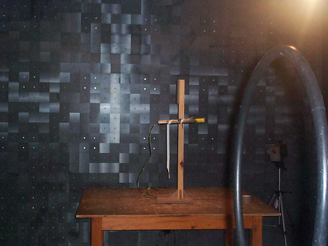
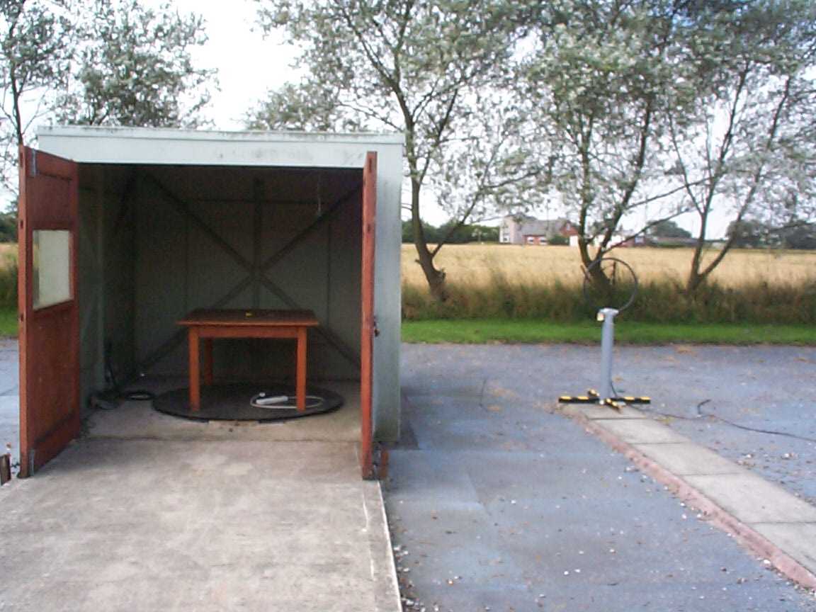
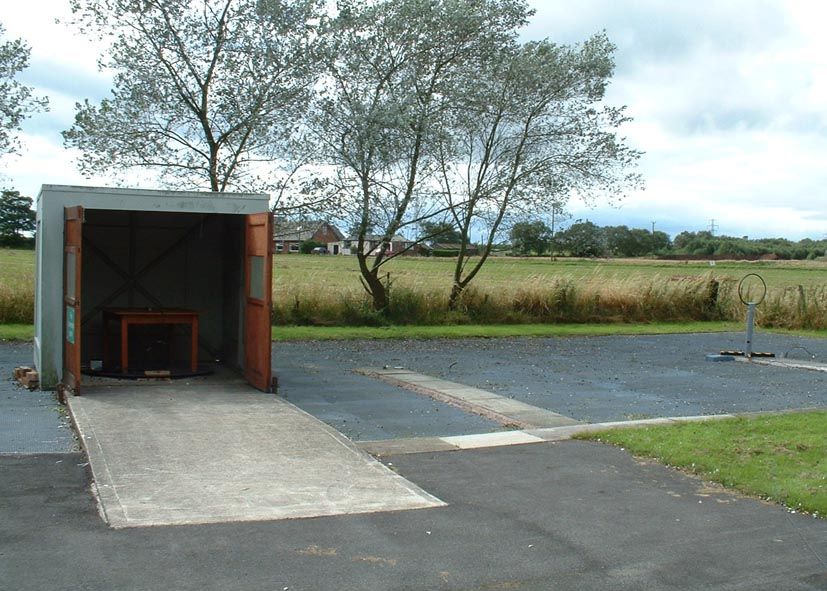
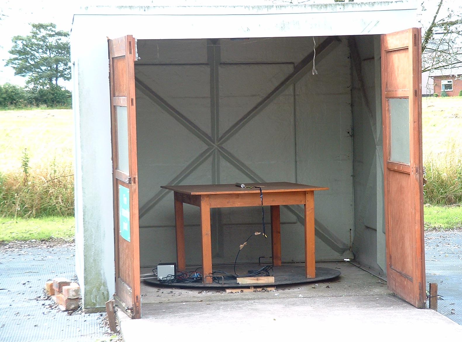
TRL C OMPLIANCE S ERVICES L TD EMC DIVISION LONG GREEN FORTHAMPTON GLOUCESTER GL19 4QH UNITED KINGDOM TELEPHONE +44 (0)1684 833818 FAX +44 (0)1684 833858 E- MAIL [email protected] www.trlcompliance.com 0728 TEST REPORT NO:RU1014/3961 COPY NO: ISSUE NO:1 FCC ID:K68ND2585 REPORT ON THE SUPPLEMENTARY MEASUREMENTS AT A DISTANCE OF 10 METRES OF A Radiodection Ltd. Wireline DataSonde WITH RESPECT TO THE FCC RULES CFR 47, PART 15.209 INTENTIONAL RADIATOR SPECIFICATION TEST DATE: 13 th AUGUST 2002 TESTED BY:J CHARTERS APPROVED BY:P GREEN PRINCIPAL ENGINEER DATE:15 th August 2002 Distribution: Copy Nos:1.Radiodection Ltd. 2.FCC EVALUATION LABORATORIES 3.TRL EMC THIS DOCUMENT MAY BE REPRODUCED ONLY IN ITS ENTIRETY AND WITHOUT CHANGE AND SHOULD BE READ IN CONJUNCTION WITH TRL COMPLIANCE SERVICES REPORT RU1014/3804 iss2. RF335 iss02RU1014/3961Page 2 of 10 CONTENTS PAGE TEST RESULTS4-7 ANNEX PHOTOGRAPHSA PHOTOGRAPH No. 1: Test setup Notes: 1.Component failure during testYES NO [ ] [X] 2.If Yes, details of failure: 3.The facilities used for the testing …
Text truncated - open the document above for the full version.
Contact Information
Applicant
Andrew Brown(Principal Engineer)
Technical Contact
Test Firm
TRL EMC LimitedNeil Roche
Technical Specifications
| # | Rule Parts | Frequency Range | Power Output | Emission |
|---|---|---|---|---|
| 1 | 15C | 0.033686 MHz - 0.034097 MHz | - | 4K80A3D |
Other Applications from Radiodetection Ltd
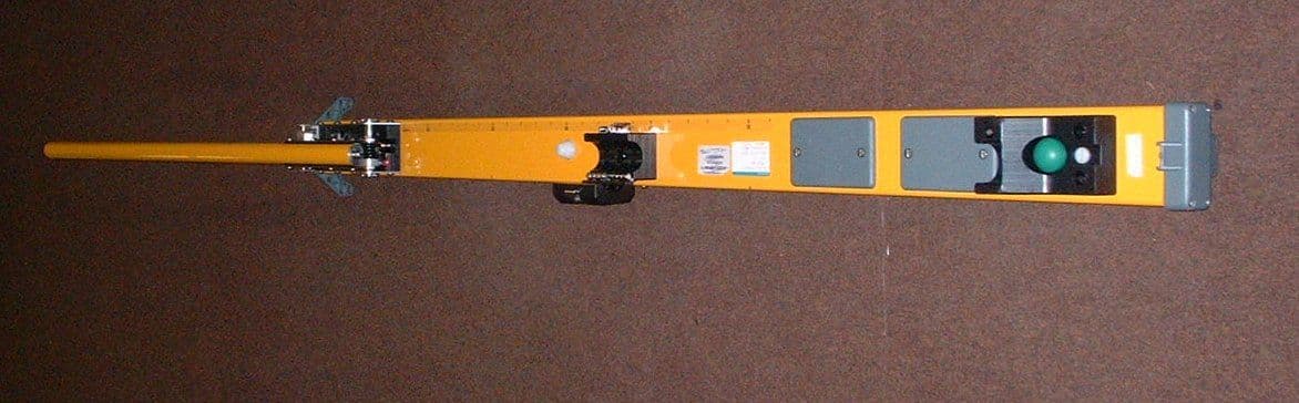
K68AA2614
Nov 19, 200220ft Vector Bar type 10/AA 2614
Equipment Class
DSC - Part 15 Security/Remote Control Transmitter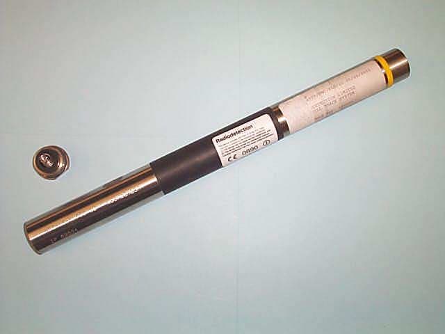
K68ND241A
Jun 21, 2001Low Frequency Drill Location Device
Equipment Class
DCD - Part 15 Low Power Transmitter Below 1705 kHz
K68ND241B
Jun 21, 2001Low Frequency Drill Location Device
Equipment Class
DCD - Part 15 Low Power Transmitter Below 1705 kHz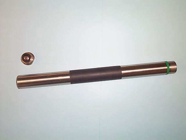
K68ND241C
Jun 21, 2001Low Frequency Drill Location Device
Equipment Class
DCD - Part 15 Low Power Transmitter Below 1705 kHz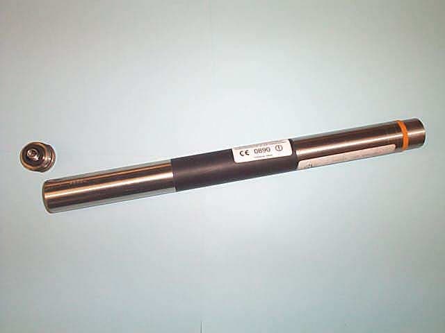
K68ND241D
Jun 21, 2001Low Frequency Drill Location Device
Equipment Class
DCD - Part 15 Low Power Transmitter Below 1705 kHz