K95APV5VHF FM Portable transceiver
BK Technologies, Inc.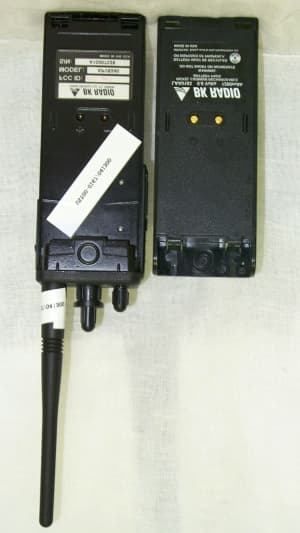
Click to zoom
Application Details
- Equipment Class
- TNF - Licensed Non-Broadcast Transmitter Held to Face
- Date of Grant
- Sep 04, 2000
- Application Purpose
- Original Equipment
- Date of Application
- Jul 19, 2000
- Equipment Note
- VHF FM Portable transceiver
- Frequency Range
- 136.00000000 - 174.00000000
- Company
- BK Technologies, Inc.
- Country
- United States
Documents & Files
Document Text
Text extracted from the exhibit documents filed with the FCC. Open a document above to read the original.
Users Manual
1 Aurora User’s Manual AURORA SERIES PORTABLE RADIO User’s Manual 2 BK Radio 3 Aurora User’s Manual 1 – Radio with Belt Clip 1 – Flexible, Helical-Wound Antenna 1 – User’s Manual (P/N 7001-30927-401) PACKING LIST CAUTION Do NOT operate a damaged radio. Aurora! WELCOME ...................................................................... 8 INTRODUCTION ............................................................. 9 Optional Accessories ................................................. 9 External Speaker/Microphone .............................. 9 External VOX Headset ......................................... 9 Battery Packs ....................................................... 9 FCC REQUIREMENTS ............................................ 10 SAFETY PRECAUTIONS ........................................ 10 Features ........................................................................ 11 Basic and Advanced Model Radios ......................... 11 Advanced Model Radios Only ................................. 11 Dealer Programmable Options ................................ 12 TABLE OF CONTENTS 4 BK Radio Before Using Your Radio ............................................... 13 Battery Installation and Removal ............................. 13 Antenna Installation and Removal ........................... 14 Radio Views .................................................................. 15 Aurora Radio Controls .................................................. 16 Front View ................................................................ 16 Display ................................................................ 16 Backlight ............................................................. 17 Keypad ............................................................... 17 Speaker .............................................................. 17 Top View .................................................................. 18 Status Indicator .................................................. 18 On/Off Volume Knob ........................................... 18 Squelch Knob ..................................................... 18 Programmable Three-Position Switch ................ 20 Emergency Button .............................................. 20 Channel Selector Knob ...................................... 20 Side Views ............................................................... 21 PTT Switch ......................................................... 21 Programmable Softkey Buttons .......................... 21 Options Connector ............................................. 22 Basic Operation ............................................................. 23 Receive .................................................................... 23 TRANSMIT ............................................................... 24 Code Guard Operation .................................................. 25 Code Guard Receive ............................................... 25 Code Guard Transmit .............................................. 26 TABLE OF CONTENTS 5 Aurora User’s Manual Built-in Features ............................................................ 27 Audio ........................................................................ 27 Audio Options .......................................................... 28 Battery-Saver Feature ............................................. 29 VOX Operation ........................................................ 29 Channel Selector ..................................................... 30 HI/LOW Transmit Power .......................................... 31 Function Menu ......................................................... 32 Mode Selections ................................................. 32 Backlite ............................................................... 33 Selecting and Activating Frequently Called “Phone List” Numbers ......................................... 34 Editing Frequently Called Numbers ................... 35 DTMF Encoding ....................................................... 36 ANI Encoding ........................................................... 36 Transmit Time-Out Timer ......................................... 37 Talk Around .............................................................. 37 Man-Down Switch .................................................... 37 Emergency Group/Channel ..................................... 38 Activation ................................................................. 38 Enabling/Disabling ................................................... 39 Transmit Speed and Frequency ............................... 39 Operating Modes ........................................................... 40 Manual Mode ........................................................... 40 Tone/Monitor Toggle ........................................... 41 Code Guard Mode .............................................. 42 Variable Guard ................................................... 43 TABLE OF CONTENTS 6 BK Radio Scan Operation ....................................................... 43 Talkback Scan .................................................... 43 Scan All Groups ................................................. 44 Change the Scan List ......................................... 44 Scanning Options ............................................... 44 Scan Delay ......................................................... 44 Talk Around ........................................................ 45 Scan in Tone Mode ............................................. 46 Scan in Monitor Mode ........................................ 46 Transmit on Priority Channel .............................. 46 Channel Scan Delete/Add .................................. 47 Priority Scan ....................................................... 48 Priority Scan with Code Guard ........................... 48 Priority Modes ..................................................…
Text truncated - open the document above for the full version.
Cover Letter(s)
FCC ID: K95APV5
External Photos
FCC ID: K95APV5 SECTION 5 PHOTOGRAPHS FCC ID: K95APV5 PHOTOS OF THE TESTED EUT The following photos are attached: Photo 1.EUT, Front View Photo 2.EUT, Rear View Photo 3.EUT, Left Side Photo 4.EUT, Right Side Photo 5.EUT, Battery Removed Photo 6. EUT, Case Opened Photo 7.EUT, Keyboard/Display Board Photo 8.EUT, Keyboard/Display Removed Photo 9.EUT, Shield Removed from Main PCB Photo 10.EUT, Top View of Main PCB Photo 11.EUT, Bottom View of Main PCB Photo 12. EUT, View Showing Main PCB Removed FCC ID: K95APV5 Photo 1.EUT, Front View FCC ID: K95APV5 Photo 2.EUT, Rear View FCC ID: K95APV5 Photo 3.EUT, Left Side FCC ID: K95APV5 Photo 4.EUT, Right Side FCC ID: K95APV5 Photo 5.EUT, Battery Removed
ID Label/Location Info
FCC ID: K95APV5 SECTION 3 LABELING INFORMATION FCC ID: K95APV5
Internal Photos
FCC ID: K95APV5 Photo 6. EUT, Case Opened FCC ID: K95APV5 Photo 7.EUT, Keyboard/Display Board FCC ID: K95APV5 Photo 8.EUT, Keyboard/Display Removed FCC ID: K95APV5 Photo 9.EUT, Shield Removed from Main PCB FCC ID: K95APV5 Photo 10.EUT, Top View of Main PCB FCC ID: K95APV5 Photo 11.EUT, Bottom View of Main PCB FCC ID: K95APV5 Photo 12. EUT, View Showing Main PCB Removed
Parts List/Tune Up Info
FCC ID: K95APV5 SECTION 6 DETAILED RF TECHNICAL INFORMATION FCC ID: K95APV5 Theory of Operation Equipment Description The APV series radios are portable (handheld) VHF transceivers operating in the 136 to 174 MHz band using frequency modulation. The units are designed for use in the Land Mobile Services, both domestic and foreign. They are multi-channel digitally synthesized radios using a single temperature compensated crystal oscillator. Usable channels are dealer programmable from 136 to 174 MHz in 2.5 kHz increments. The radios are available in a sixteen-channel configuration (APV5016) with a single bank or group and in larger configurations (APV5240) using multiple banks. Channel frequency information is stored in an EEPROM with up to 15 banks of channels available to yield a capability of up to 240 channels. The APV5240 is comprised of a main printed circuit board (PCB) assembly and a front panel display printed circuit board assembly, and the APV5016 is only comprised of a main board assembly. The main PCB consists of the micro-controller, EEPROM, transmitter, receiver, and audio circuits. The EEPROM is used to store frequencies, configurations, and other user specific information. The front panel assembly of the keyboard/display model consists of the LCD display, display controller circuit, and keypad. Main PCB Assembly Microprocessor Control The Microprocessor (U12) controls the radio functions such as loading the synthesizer, detecting the keyboard and various switch modes, adjusting the transmitter and receiver circuit tuning drivers, and generating and detecting the various signaling formats. Regulation The 6V switching power supply U14 supplies voltage to U11 (5-Volt regulator), U13 (5-Volt regulator), U16 (5-Volt regulator), U27 (5-Volt regulator), U17 and U18 (IF analog switches), and to U15 (Sub-IF IC). U11 supplies 5 volts to U12 (Microprocessor), U4 (D/A converter), U8 (EEPROM) and to all the controlling and logic switching circuits. U13 supplies 5 volts to the various RX audio circuits such as U1 (Audio LSI), U7 (DTMF Receiver), and the various op amps associated with these circuits. U16 supplies 5 volts to Q13 (IF amplifier) and to U19 (pre-selector tuners). U27 supplies 5 volts to G1 (TCXO), U21 (Synthesizer ASIC), U29 (Phase Detector), U30 (Loop Filter) and, U31 (Pre-scalar). FCC ID: K95APV5 Synthesizer U21 is a 44pin QFP Synthesizer ASIC IC. It provides highly stable, low noise, frequency source for 2.5 kHz, 5 kHz, and 6.25 kHz channel spacing resolution. The ASIC includes a Reference Divider, Phase Accumulator, Digital Compensation, Phase Detector, and CPU interface and decoder. The synthesizer is a Fractional-N type based on the 3 rd order loop of the ASIC design. The phase detector including U28 provides a DC voltage that is proportional to the phase error between the divided down frequency from the ASIC and the divided down carrier frequency. This voltage is fed to the loop filter and then to the VCO. This error correction voltage causes the VCO frequency adjustment in a direction to maintain phase lock between the divided down frequency. The synthesizer employs a two-point modulation scheme. One modulation point leads to the VCO and the other point leads to the phase detector. The phase detector modulation point allows true data to be modulated. TCXO The hybrid 12.8 MHz temperature compensated crystal oscillator (G1) is fed into he ASIC as the reference oscillator for all frequency synthesis. The hybrid design with temperature compensations provides less than +/- 2.5ppm of drift between -30°C and +60°C. The ASIC divides the reference into other external references such as 8 MHz for U12 (Microprocessor), 320 kHZ/349 kHz for U14 (Switching Regulator). Prescaler The “dual modulus” prescaler U31 is the frequency divider in the feedback path of the synthesizer. Loop Filter The loop filter including U30 removes noise and unwanted frequency components from the output of the phase detector (U29). The synthesizer employs a multiple filter bandwidth design, thus, optimizing the filter response during steady state or scanning modes. VCO Q27 and Q28 are the TX/RX VCO’s. They are configured as a Colpitts, low phase noise type oscillators. Each VCO has a Coarse and Fine voltage tune line leading in from the synthesizer to varactors diodes CR41-48. VCO selection is through PUMX transistors Q25 and Q26. The transmitter audio is fed to CR67 and CR40 for VCO modulation. FCC ID: K95APV5 Receiver Section The receive signal from the antenna connector is fed through the harmonic filter and split from the TX path to the RF amplifier (Q12) and pre-selectors. “Tuner” voltage amplifiers of U19 tune the pre-selector varactors CR18-CR33 for the desired selectivity. The RF signal is then mixed with the RX LO drive signal from the VCO. The major components of the active mixer consist of T1, T2, and Q14-17. From the mixer, the 16.9 MHz “resulting” IF frequency is filtered through FL1 a 4-pole crystal filter. The IF signal is then amplified by Q13 and fed into the 2 nd mixer input of U15 of the sub-IF IC. U15 includes the 2 nd mixer, 2 nd IF amp, “Limiter”, and “Quadrature”. The 16.445 MHz 2 nd LO crystal Y2 is connected to the oscillator input/output for 2 nd LO mixing. Ceramic filters FL3, FL4, FL8, and FL9 provide 2nd IF wide and narrow band filtering through the respective ports of U15. The discriminated audio output from pin 8 is split off into two circuit directions. One path delivers a discriminator voltage used for calibration and the other path leads to audio processing circuits and to U1 the Audio LSI IC. Audio The receiver audio from the discriminator is split again and filtered before being processed in the Audio LSI IC. One path (voice) is connected to a 300Hz high pass filters including U5 and U10 before the LSI processing. The other path (sub-audio) is connected to a 250 Hz sub LPF including U5 to pass the sub-audio tones to the DC restoration circuit including U34 and CR2-3. …
Text truncated - open the document above for the full version.
Parts List/Tune Up Info
FCC ID: K95APV5 SECTION 6 DETAILED RF TECHNICAL INFORMATION FCC ID: K95APV5 Theory of Operation Equipment Description The APV series radios are portable (handheld) VHF transceivers operating in the 136 to 174 MHz band using frequency modulation. The units are designed for use in the Land Mobile Services, both domestic and foreign. They are multi-channel digitally synthesized radios using a single temperature compensated crystal oscillator. Usable channels are dealer programmable from 136 to 174 MHz in 2.5 kHz increments. The radios are available in a sixteen-channel configuration (APV5016) with a single bank or group and in larger configurations (APV5240) using multiple banks. Channel frequency information is stored in an EEPROM with up to 15 banks of channels available to yield a capability of up to 240 channels. The APV5240 is comprised of a main printed circuit board (PCB) assembly and a front panel display printed circuit board assembly, and the APV5016 is only comprised of a main board assembly. The main PCB consists of the micro-controller, EEPROM, transmitter, receiver, and audio circuits. The EEPROM is used to store frequencies, configurations, and other user specific information. The front panel assembly of the keyboard/display model consists of the LCD display, display controller circuit, and keypad. Main PCB Assembly Microprocessor Control The Microprocessor (U12) controls the radio functions such as loading the synthesizer, detecting the keyboard and various switch modes, adjusting the transmitter and receiver circuit tuning drivers, and generating and detecting the various signaling formats. Regulation The 6V switching power supply U14 supplies voltage to U11 (5-Volt regulator), U13 (5-Volt regulator), U16 (5-Volt regulator), U27 (5-Volt regulator), U17 and U18 (IF analog switches), and to U15 (Sub-IF IC). U11 supplies 5 volts to U12 (Microprocessor), U4 (D/A converter), U8 (EEPROM) and to all the controlling and logic switching circuits. U13 supplies 5 volts to the various RX audio circuits such as U1 (Audio LSI), U7 (DTMF Receiver), and the various op amps associated with these circuits. U16 supplies 5 volts to Q13 (IF amplifier) and to U19 (pre-selector tuners). U27 supplies 5 volts to G1 (TCXO), U21 (Synthesizer ASIC), U29 (Phase Detector), U30 (Loop Filter) and, U31 (Pre-scalar). FCC ID: K95APV5 Synthesizer U21 is a 44pin QFP Synthesizer ASIC IC. It provides highly stable, low noise, frequency source for 2.5 kHz, 5 kHz, and 6.25 kHz channel spacing resolution. The ASIC includes a Reference Divider, Phase Accumulator, Digital Compensation, Phase Detector, and CPU interface and decoder. The synthesizer is a Fractional-N type based on the 3 rd order loop of the ASIC design. The phase detector including U28 provides a DC voltage that is proportional to the phase error between the divided down frequency from the ASIC and the divided down carrier frequency. This voltage is fed to the loop filter and then to the VCO. This error correction voltage causes the VCO frequency adjustment in a direction to maintain phase lock between the divided down frequency. The synthesizer employs a two-point modulation scheme. One modulation point leads to the VCO and the other point leads to the phase detector. The phase detector modulation point allows true data to be modulated. TCXO The hybrid 12.8 MHz temperature compensated crystal oscillator (G1) is fed into he ASIC as the reference oscillator for all frequency synthesis. The hybrid design with temperature compensations provides less than +/- 2.5ppm of drift between -30°C and +60°C. The ASIC divides the reference into other external references such as 8 MHz for U12 (Microprocessor), 320 kHZ/349 kHz for U14 (Switching Regulator). Prescaler The “dual modulus” prescaler U31 is the frequency divider in the feedback path of the synthesizer. Loop Filter The loop filter including U30 removes noise and unwanted frequency components from the output of the phase detector (U29). The synthesizer employs a multiple filter bandwidth design, thus, optimizing the filter response during steady state or scanning modes. VCO Q27 and Q28 are the TX/RX VCO’s. They are configured as a Colpitts, low phase noise type oscillators. Each VCO has a Coarse and Fine voltage tune line leading in from the synthesizer to varactors diodes CR41-48. VCO selection is through PUMX transistors Q25 and Q26. The transmitter audio is fed to CR67 and CR40 for VCO modulation. FCC ID: K95APV5 Receiver Section The receive signal from the antenna connector is fed through the harmonic filter and split from the TX path to the RF amplifier (Q12) and pre-selectors. “Tuner” voltage amplifiers of U19 tune the pre-selector varactors CR18-CR33 for the desired selectivity. The RF signal is then mixed with the RX LO drive signal from the VCO. The major components of the active mixer consist of T1, T2, and Q14-17. From the mixer, the 16.9 MHz “resulting” IF frequency is filtered through FL1 a 4-pole crystal filter. The IF signal is then amplified by Q13 and fed into the 2 nd mixer input of U15 of the sub-IF IC. U15 includes the 2 nd mixer, 2 nd IF amp, “Limiter”, and “Quadrature”. The 16.445 MHz 2 nd LO crystal Y2 is connected to the oscillator input/output for 2 nd LO mixing. Ceramic filters FL3, FL4, FL8, and FL9 provide 2nd IF wide and narrow band filtering through the respective ports of U15. The discriminated audio output from pin 8 is split off into two circuit directions. One path delivers a discriminator voltage used for calibration and the other path leads to audio processing circuits and to U1 the Audio LSI IC. Audio The receiver audio from the discriminator is split again and filtered before being processed in the Audio LSI IC. One path (voice) is connected to a 300Hz high pass filters including U5 and U10 before the LSI processing. The other path (sub-audio) is connected to a 250 Hz sub LPF including U5 to pass the sub-audio tones to the DC restoration circuit including U34 and CR2-3. …
Text truncated - open the document above for the full version.
Schematics
FCC ID: K95APV5 SECTION 4 BLOCK DIAGRAM / SCHEMATICS FCC ID: K95APV5 FCC ID: K95APV5 FCC ID: K95APV5
Schematics
FCC ID: K95APV5 FCC ID: K95APV5
Schematics
FCC ID: K95APV5 FCC ID: K95APV5
Test Report
FCC ID: K95APV5 Figure 6b Spurious Emissions at Antenna Terminals (Middle) FCC ID: K95APV5 Figure 6c Spurious Emissions at Antenna Terminals (High) FCC ID: K95APV5 2.10 Field Strength of Spurious Radiation (FCC Section 2.1053) Spurious emissions were evaluated from 30 MHz to 2.0 GHz at an EUT to antenna distance of 3 meters. The EUT was tested with a new battery. Measurements for 30 to 1000 MHz were made with the analyzer's bandwidth set to 120 kHz. Measurements above 1 GHz were made with the analyzer's bandwidth set to 1 MHz. Results are shown in Table 4. Following is an example of how the data was calculated. The spurious radiation measured is interpolated to 30 meters using: dBm @ 3 meters + 20 log(3/30) = dBm @ 30 meters this level is compared to the level a transmitter would produce at 30 meters if connected to a 1/2 wave dipole using: E = (30 P t G t ) 1/2 volts per meter d E = Field intensity (volts per meter) P t = Power output of transmitter (watts) G t = Gain of antenna (1.64 for 1/2 wave dipole) d = distance (meters) For Example: A 25 watt transmitter would produce [(30)(25)(1.64)] 1/2 volts per meter 30.0 = 1,150,635 microvolts per meter @ 30 meters FCC ID: K95APV5 FCC Minimum Standard FCC Part 22.359, 74.462, 80.211 and 90.210 (25 kHz bandwidth only) On any frequency removed from the center of the assigned channel by more than 250 percent at least: Low: 43 + 10 log (P Watts ) = 43 + 10 log (4.8) = 49.8 dB Middle: 43 + 10 log (P Watts ) = 43 + 10 log (5.2) = 50.2 dB High: 43 + 10 log (P Watts ) = 43 + 10 log (4.9) = 49.9 dB FCC Part 90.210 (12.5 kHz Bandwidth only) On any frequency removed from the center of the authorized bandwidth by a displacement frequency (f d in kHz) of more than 12.5 kHz at least: Low: 50 + 10 log (P Watts ) = 50 + 10 log (4.8) = 56.8 dB Middle: 50 + 10 log (P Watts ) = 50 + 10 log (5.2) = 57.2 dB High: 50 + 10 log (P Watts ) = 50 + 10 log (4.9) = 56.9 dB NOTE: In general, the worse case attenuation requirement shown above was applied. FCC ID: K95APV5 FIELD STRENGTH OF SPURIOUS RADIATION Test Date:May 4, 2000 - May 10, 2000 UST Project:00-0167 Customer:RELM Communication, Inc. Model:Aurora (APV5240 & APV5016) FCC Minimum Standard: 50 + 10 log (4.8) = 56.8 dB Fundamental = Corrected Reading in Far Field (30m) = +7.2 dBm TABLE 4a (Low) FREQ (MHz) MEASUREMENT @ 3 m (dBm) CORRECTION AF + CL - AMP GAIN CORRECTED MEASUREMENT @ 30 m (dBm) ATTENUATED LEVEL BELOW CARRIER POWER (dB) 409.0-66.020.6-65.472.6 545.0-69.024.0-65.072.2 681.0-70.027.2-62.870.0 1499.5-53.2-5.6-78.886.0 SAMPLE CALCULATION: Results dBm @ 30 m: -66.0 + 20.6 - 20 = -65.4 CONVERSION FROM 3m to 30m = 20 log (3/30) = -20 dBm Test Results Reviewed By: Name: Tim R. Johnson FCC ID: K95APV5 FIELD STRENGTH OF SPURIOUS RADIATION Test Date:May 4, 2000 - May 10, 2000 UST Project:00-0167 Customer:RELM Communication, Inc. Model:Aurora (APV5240 & APV5016) FCC Minimum Standard: 50 + 10 log (5.2) = 57.2 dB Fundamental = Corrected Reading in Far Field (30m) = +7.5 dBm TABLE 4b (Middle) FREQ (MHz) MEASUREMENT @ 3 m (dBm) CORRECTION AF + CL - AMP GAIN CORRECTED MEASUREMENT @ 30 m (dBm) ATTENUATED LEVEL BELOW CARRIER POWER (dB) 311.0-62.018.5-63.571.0 466.0-60.022.2-62.269.7 1399.4-45.5-6.1-71.679.1 SAMPLE CALCULATION: Results dBm @ 30 m: -62.0 + 18.5 - 20 = -63.5 CONVERSION FROM 3m to 30m = 20 log (3/30) = -20 dBm Test Results Reviewed By: Name: Tim R. Johnson FCC ID: K95APV5 FIELD STRENGTH OF SPURIOUS RADIATION Test Date:May 4, 2000 - May 10, 2000 UST Project:00-0167 Customer:RELM Communication, Inc. Model:Aurora (APV5240 & APV5016) FCC Minimum Standard: 50 + 10 log (4.9) = 56.9 dB Fundamental = Corrected Reading in Far Field (30m) = +7.3 dBm TABLE 4c (High) FREQ (MHz) MEASUREMENT @ 3 m (dBm) CORRECTION AF + CL - AMP GAIN CORRECTED MEASUREMENT @ 30 m (dBm) ATTENUATED LEVEL BELOW CARRIER POWER (dB) 347.0-65.019.1-65.973.2 521.0-68.023.5-64.571.8 1390.4-50.4-6.1-76.583.8 SAMPLE CALCULATION: Results dBm @ 30 m: -65.0 + 19.1 - 20 = -65.9 CONVERSION FROM 3m to 30m = 20 log (3/30) = -20 dBm Test Results Reviewed By: Name: Tim R. Johnson FCC ID: K95APV5 2.11 Frequency Stability (FCC Section 2.1055) The frequency tolerance of the carrier signal was measured by while ambient temperature was varied from -30 to 50 degrees centigrade. The frequency tolerance was verified at 10 degree increments. The EUT was tested while powered from 9.6 VDC. Additionally, the supply voltage was varied from 85% to 115% of the nominal value (except for hand carried, battery powered equipment which was additionally measured at battery endpoint). The data is shown in the following tables and figures. FCC Minimum Standard FCC Part 22.355 5.0 ppm for Mobile > 3 Watts, 50 ppm for ≤ 3 Watts FCC Part 74.464 0.0005% (5 ppm) for > 3 Watts, 0.005% (50 ppm) for ≤ 3 Watts FCC Part 80.209 5.0 ppm for Coast Stations > 3 Watts, 10 ppm for ≤ 3 Watts FCC Part 90.213 5.0 ppm for > 2 Watts FCC ID: K95APV5 FCC ID: K95APV5 FCC ID: K95APV5 FCC ID: K95APV5 FCC ID: K95APV5 FCC ID: K95APV5 2.12 Transient Frequency Behavior (FCC Section 90.214) Information regarding this requirement has been supplied by RELM Communications. Plots are provided for both 25 kHz and 12.5 kHz Channel Bandwidths in the following figures. FCC ID: K95APV5 25 kHz Bandwidth FCC ID: K95APV5 12.5 kHz Bandwidth
Test Report
FCC ID: K95APV5 2.5 Antenna Description Antennas are 3 rd party sourced. Manufacturer:Centurioun Type: Helical Wound Molded Rubber Flex Model Number:LAA0870A (136-150 MHz) LAA0870B (150-162 MHz) LAA0870C (162-174 MHz Gain:Not specified by Relm Communications, Inc. Connector:SMA FCC ID: K95APV5 2.6 RF Power Output (FCC Section 2.1046) The EUT was directly connected to a spectrum analyzer with the input resistance set to 50Ω. An external 50 dB attenuation was used during the test. The measured results are shown in Table 3 and Figure 3. FCC Minimum Standard FCC Part 22 <150 Watts FCC Part 74.461 Power delivered to antenna must be < 100 Watts FCC Part 80.215 Maximum power at the input terminal to the antenna is 50 Watts FCC Part 90.205 Power dependent upon station's antenna HAAT and required service area and may be from 1 to 500 Watts. FCC ID: K95APV5 TABLE 3 RF POWER OUTPUT Test Date:April 24, 2000 UST Project:00-0167 Customer:RELM Communication, Inc. Model:Aurora (APV5240 & APV5016) Frequency of Fundamental (MHz) Measurement (Watt)* FCC Limit (Watt) 136.34.8Varies 155.55.2Varies 173.84.9Varies Note: The power output may depend upon the intended use of the EUT. For all tests, the EUT was set to near maximum conditions. The EUT requires a FCC license and is programmed for use by local BK Radio Dealers. Test Results Reviewed By Signature: Name: Timothy R. Johnson FCC ID: K95APV5 Figure 3a. RF Power Output (Low Channel) FCC ID: K95APV5 Figure 3b. RF Power Output (Low Channel) FCC ID: K95APV5 Figure 3c. RF Power Output (Low Channel) FCC ID: K95APV5 2.7 Modulation Characteristics (FCC Section 2.1047) Where applicable, the modulation characteristics of the EUT have been supplied by RELM Communication, Inc. as stipulated by the following FCC requirements: a) Equipment which utilizes voice modulated communication shall show the frequency response of the audio modulating circuit over a range of 100 to 5000 Hz. For equipment which is required to have a low pass filter, the frequency response of the filter, or all of the circuitry installed between the modulation limited and the modulated stage shall be supplied. b) Equipment which employs modulation limiting, a curve showing the percentage of modulation versus the modulation input voltage shall be supplied. FCC Minimum Standard FCC Part 22 None FCC Part 74.463 Each new remote pickup broadcast station with a power output in excess of 3 watts shall be equipment with a device which will automatically prevent modulation in excess of the limits. If frequency modulation is employed, the emissions shall conform to the emission requirements of 74.462. FCC Part 80.213 (a) When phase of frequency modulation is used in the 156-162 MHz and 216-220 MHz bands, the peak modulation must be maintained between 75 and 100 percent. A frequency deviation of ± 5 kHz is defined as 100 percent peak modulation. (b) Transmitters using F3E emission must have a modulation limiter to prevent any modulation over 100 percent (d) Ship and coast station transmitters operating in the 156-162 MHz and 216-220 MHz bands must be capable of proper operation with a frequency deviation of ± 5 kHz. (e) Coast station transmitters operated in the 156-162 MHz band must be equipped with an audio low-pass filter. The filter must be installed between the modulation limiter and the modulated radio frequency stage. At frequencies between 3 kHz and 20 kHz it must have an attenuation greater than at 1 kHz by at least 60 log (f/3) db. At frequencies above 20 kHz the attenuation must be at least 50 dB greater than at 1 kHz. FCC Part 90.205 Transmitters utilizing analog emissions that are equipped with an audio low-pass filter must meet the emission limitations must meet proper emissions mask of 90.210. FCC ID: K95APV5 Figure 4a. Modulation Characteristics FCC ID: K95APV5 Figure 4b. Modulation Characteristics FCC ID: K95APV5 Figure 4c. Modulation Characteristics FCC ID: K95APV5 2.8 Occupied Bandwidth (FCC Section 2.1049) EUT was modulated by a 2500 Hz signal. The bandwidth of the fundamental was measured by RELM Communication, Inc. using a spectrum analyzer, as shown in Figure 5a through Figure 5b. FCC Minimum Standard FCC Part 22.359, 74.462, 80.211 and 90.210 (25 kHz bandwidth only) For any frequency removed from the center of the assigned channel by more than 50 percent up to and including 100 percent of the authorized bandwidth, at least 25 dB. On any frequency removed from the center of the assigned channel by more than 100 percent up to and including 250 percent, at least 35 dB. On any frequency removed from the center of the assigned channel by more than 250 percent at least: Low: 43 + 10 log (P Watts ) = 43 + 10 log (4.8) = 49.8 dB Middle: 43 + 10 log (P Watts ) = 43 + 10 log (5.2) = 50.2 dB High: 43 + 10 log (P Watts ) = 43 + 10 log (4.9) = 49.9 dB The resolution bandwidth was 300 Hz or greater for measuring up to 250 kHz from the edge of the authorized frequency segment, and 30 kHz or greater for measuring more than 250 kHz from the authorized frequency segment. FCC Part 90.210 (12.5 kHz Bandwidth only) For any frequency removed from the center of the authorized bandwidth f 0 to 5.625 kHz removed from f 0 , 0 dB. On any frequency removed from the center of the authorized bandwidth by a displacement frequency (f d in kHz) of more than 5.626 kHz but no more than 12.5 kHz, at least 7.27 (f d - 2.…
Text truncated - open the document above for the full version.
Contact Information
Applicant
Brian W. Jones(VP Engineering)
Technical Contact
United States TechnologiesTimothy R Johnson
[email protected]770-740-0717
3505 Francis Circle · Alpharetta, Georgia · United States
Non-Technical Contact
United States TechnologiesTimothy R Johnson
[email protected]770-740-0717
Test Firm
US TechSandy McEnery
Technical Specifications
| # | Rule Parts | Frequency Range | Power Output | Emission | Tolerance |
|---|---|---|---|---|---|
| 2 | 22,74,90.21 | 136 MHz - 174 MHz | 5.2 W | 11K0F3E | 5 ppm |
Other Applications from BK Technologies, Inc.

K95BKR9000-2
May 29, 2023Multi-Band Portable Radio VHF/UHF/700/800
Equipment Class
DTS - Digital Transmission System
K95BKR5000-V
Apr 15, 2020Handheld Transceiver
Equipment Class
TNF - Licensed Non-Broadcast Transmitter Held to Face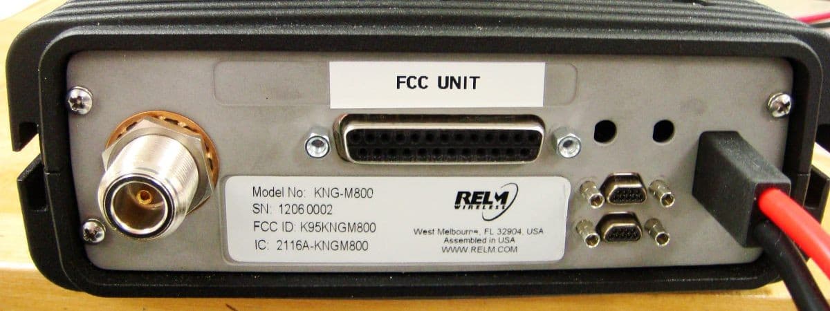
K95KNGM800
Jun 21, 2012MOBILE TRANSCEIVER
Equipment Class
TNB - Licensed Non-Broadcast Station Transmitter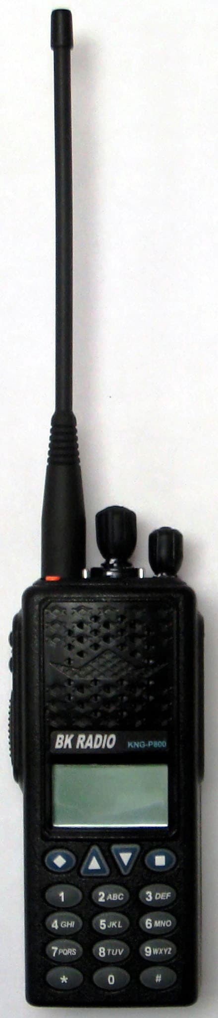
K95KNGP800C
Aug 17, 2011HANDHELD TRANSCEIVER
Equipment Class
TNF - Licensed Non-Broadcast Transmitter Held to Face
K95KNGM500
Dec 07, 2010MOBILE UHF DIGITAL RADIO
Equipment Class
TNB - Licensed Non-Broadcast Station Transmitter