K95DMH599VHF TRANSCEIVER
BK Technologies, Inc.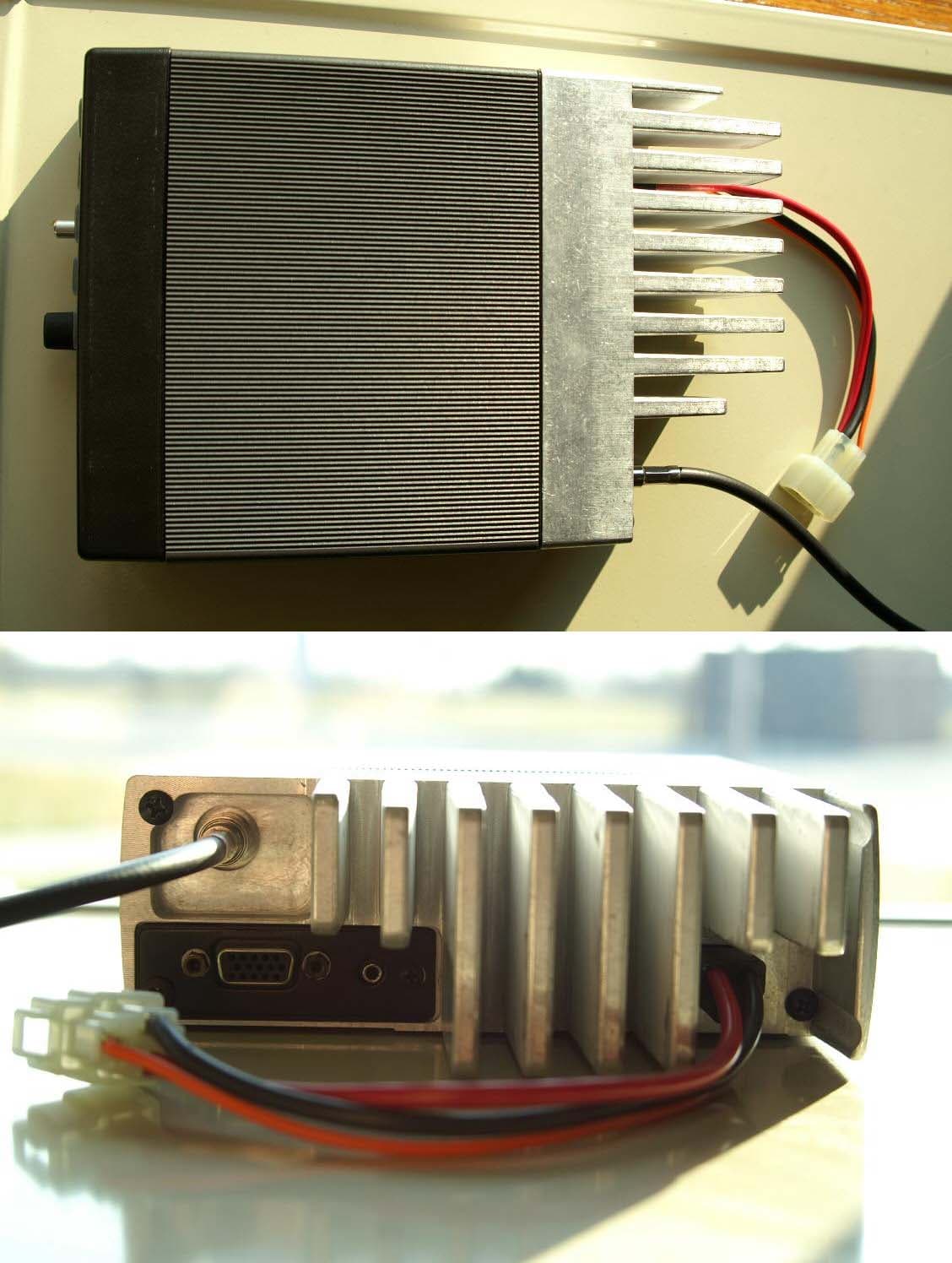
Click to zoom
Application Details
- Equipment Class
- TNB - Licensed Non-Broadcast Station Transmitter
- Date of Grant
- Jun 20, 2005
- Application Purpose
- Original Equipment
- Date of Application
- Jun 20, 2005
- Equipment Note
- VHF TRANSCEIVER
- Frequency Range
- 136.00000000 - 174.00000000
- Company
- BK Technologies, Inc.
- Country
- United States
Documents & Files
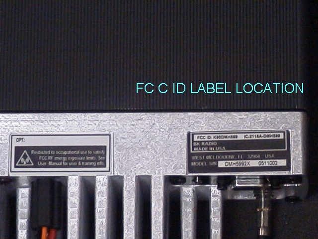
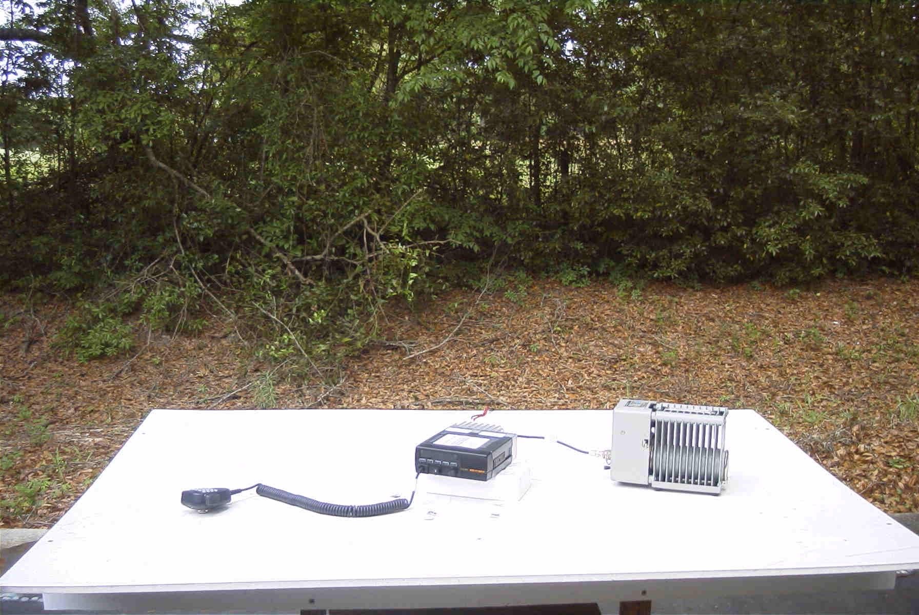
Document Text
Text extracted from the exhibit documents filed with the FCC. Open a document above to read the original.
Users Manual
BK RADIO Page 3-1 SECTION III OPERATION 3.1 INTRODUCTION This section contains information concerning the operation procedures for the BK Radio DMH APCO Project 25 digital mobile radios. To meet backwards compatibility as defined by the APCO Project 25 standard, the DMH digital mobile radio provides users the ability to interoperate with narrow or wide band analog channels as well as digital systems. Please take a moment to read the information in this manual so you can get optimum performance from your new radio. 3.1.1 FEATURES • APCO Project 25 FDMA Common Air Interface Compatible • True Mixed-Mode Operation • RX – Automatically Detect Analog or Digital Signals • TX – Optional Auto-Respond in Last-Received Mode • APCO Project 25 Conventional Operation • Group Calls • Emergency Group Calls • Unit-To-Unit Calls • User-Programmable Call List • Programmable Push Buttons • Programmable Microphone Keypad Menu • DTMF/ANI • Transmit Time-Out Timer • Group Scan • Scan Delay • Talkback Scan • Nuisance Channel Delete • Dual-Priority Scan with Channel Guard • Alphanumeric Display • Up to 400 Channels Available in 25 Groups of 16 Channels • 2.5 kHz Interstitial Frequency Capability 3.2 FCC REQUIREMENTS Your radio must be properly licensed by the Federal Communications Commission prior to use. Your BK Radio dealer can assist you in meeting these requirements. Your dealer will program each radio with your authorized frequencies, signaling codes, etc., and will be there to meet your communications needs as your system expands. Operation DMH Series VHF Radio Page 3-2 BK RADIO 3.2.1 RF ENERGY EXPOSURE AWARENESS AND CONTROL INFORMATION, AND OPERATIONAL INSTRUCTIONS FOR FCC OCCUPATIONAL USE REQUIREMENTS BEFORE USING YOUR MOBILE 2-WAY RADIO, READ THE INFORMATION BELOW WHICH CONTAINS IMPORTANT OPERATING INSTRUCTIONS FOR SAFE USAGE AND RF ENERGY AWARENESS AND CONTROL INFORMATION FOR COMPLIANCE WITH RF ENERGY EXPOSURE LIMITS IN APPLICABLE NATIONAL AND INTERNATIONAL STANDARDS. NOTICE: This radio is intended for use in occupational/controlled conditions, where users have full knowledge of their exposure and can exercise control over their exposure to meet FCC limits. This radio device is NOT authorized for general population, consumer, or any other use. This 2-way radio uses electromagnetic energy in the radio frequency (RF) spectrum to provide communications between two or more users over a distance. It uses radio frequency (RF) energy or radio waves to send and receive calls. RF energy is one form of electromagnetic energy; other forms include, but are not limited to, sunlight and x-rays. RF energy, however, should not be confused with these other forms of electromagnetic energy, which when used improperly, can cause biological damage. Very high levels of x-rays, for example, can damage tissues and genetic material. Experts in science, engineering, medicine, health and industry work with organizations to develop standards for exposure to RF energy. These standards provide recommended levels of RF exposure for both workers and the general public. These recommended RF exposure levels include substantial margins of protection. All 2-way radios are designed, manufactured, and tested to ensure they meet government established RF exposure levels. In addition, manufacturers also recommend specific operating instructions to users of 2-way radios. These instructions are important because they inform users about RF energy exposure and provide simple procedures on how to control it. Please refer to the following WEBSITES for more information on what RF energy exposure is and how to control your exposure to assure compliance with established RF exposure limits. http://www.fcc.gov/oet/rfsafety/rf-faqs.html http://www.osha.gov/SLTC/radiofrequencyradiation/index.html 3.2.2 FEDERAL COMMUNICATIONS COMMISSION REGULATIONS The FCC rules require manufacturers to comply with the FCC RF energy exposure limits for mobile 2-way radios before they can be marketed in the U.S. When 2-way radios are used as a consequence of employment, the FCC requires users to be fully aware of and able to control their exposure to meet occupational requirements. Exposure awareness can be facilitated by the use of a product label directing users to specific user awareness information. Your BK Radio 2-way radio has an RF exposure product label. Also, your BK Radio owner’s and service manuals include information and operating instructions required to control your RF exposure and to satisfy compliance requirements. Operation DMH Series VHF Radio BK RADIO Page 3-3 3.2.3 COMPLIANCE WITH RF EXPOSURE STANDARDS Your BK Radio 2-way radio is designed and tested to comply with a number of national and international standards and guidelines (listed below) for human exposure to radio frequency electromagnetic energy. This radio complies with the IEEE and ICNIRP exposure limits for occupational/controlled RF exposure environment at operating duty factors of up to 50% talk- 50% listen and is authorized by the FCC for occupational use only. In terms of measuring RF energy for compliance with the FCC exposure guidelines, your radio antenna radiates measurable RF energy only while it is transmitting (during talking), not when it is receiving (listening) or in Standby Mode. Your BK Radio 2-way radio complies with the following RF energy exposure standards and guidelines: • United States Federal Communications Commission, Code of Federal Regulations; 47 CFR §§ 1.1307, 1.1310, 2.1091 and 2.1093 • American National Standards Institute (ANSI) / Institute of Electrical and Electronic Engineers (IEEE) C95. 1-1992 • Institute of Electrical and Electronic Engineers (IEEE) C95.1-1999 Edition 3.2.4 INDUSTRY CANADA COMPLIANCE This Class B digital apparatus complies with Canadian ICES-003. Cet appareil numerique de la classe B est conforme à la norme NMB-003 Canada. 3.2.4 RF EXPOSURE COMPLIANCE AND CONTROL GUIDELINES AND OPERATING INSTRUCTIONS To control exposure to yourself and othe…
Text truncated - open the document above for the full version.
Block Diagram
DMH BLOCK DIAGRAMS Power Amp. Driver Stage Power Module To Harmonic Filter L.O. Input (from VCO) Power Control U103 S-AV32 Q102 BFR106 Synthesizer Synthesizer IC TCXO Reference Loop Filter Phase Error Synthesizer Buffer Coarse Tune Program Lines Adapt Pulse Frequency Steering VCO Buffer VCO TX Modulation RX/TX Band Switch Steering Line
External Photos
DMH Photos External Photos DMH Photos
Internal Photos
DMH Photos Internal Photos. Accessory board top side. Accessory board bottom side. DMH Photos Control board top side. Control board bottom side. DMH Photos Options board top side Options board top side DMH Photos Receiver board top side Receiver board bottom side. DMH Photos VCO board bottom side VCO board top side DMH Photos System board bottom side System board top side DMH Photos PA board top side PA board bottom side
Operational Description
SECTION IV THEORY OF OPERATION 4.1 INTRODUCTION This section contains a description of equipment and a theory of operation for the BK Radio DMH APCO Project 25 digital VHF radio. To aid in understanding the operation of the equipment, schematic diagrams are found in Section VI of this manual. 4.2 EQUIPMENT DESCRIPTION The BK Radio DMH Series radio comprises the following sub-assemblies: 4.2.1 SYSTEM BOARD This sub-assembly consists of core microprocessor, synthesizer, baseband signal processor and regulation. A casting is used to shield the synthesizer area. 4.2.2 RX BOARD This sub-assembly consists of the receiver circuitry from the front-end through the digital IF. 4.2.3 HIGH LEVEL POWER AMPLIFIER BOARD This sub-assembly consists of the transmitter power amplifier, antenna switch, harmonic filter, directional coupler and power control. 4.2.4 OPTIONS BOARD This sub-assembly consists of the audio power amp, and interfaces with both the System Board and the Control Board. 4.2.5 CONTROL BOARD This sub-assembly consists of a control head microprocessor, regulator, and vacuum florescent display circuitry. It interfaces with the front panel. 4.2.6 VCO BOARD The VCO board is a separate assembly that resides in its own shielded enclosure and interconnects with the System Board and RX Board. BK RADIO Page 4-1 Theory of Operation DMH Series VHF Radio 4.3 THEORY OF OPERATION 4.3.1 SYSTEM BOARD System board functions include: • Core Microprocessor • Voltage regulators • Synthesizer • Baseband signal processor A. Microprocessor The core microprocessor communicates with the control head microprocessor and the baseband signal processor. It controls radio functions such as adjusting the deviation and receiver tuning. An EEPROM is used to store calibration and tuning data unique to each radio. An internal clock determines the microprocessor’s operating frequency. B. Synthesizer The Synthesizer generates an RF signal either to down-convert a desired receive frequency to a fixed IF or to drive the Transmitter. The synthesizer locks the RF output frequency of a Voltage Controlled Oscillator (VCO) to a very stable frequency reference. Steering Line VCO VCO Buffer Loop Filter Synthesizer IC Synthesizer Buffer TCXO Reference RX/TX Switch TX Modulation Program Line Coarse Tune VCO Coarse Tune Filter (1) Synthesizer IC – Contains programmable counters to divide and compare the VCO output frequency to the stable TCXO reference and adjusts VCO control voltage to maintain a stable output frequency. (2) TCXO Reference – Provides a stable frequency reference over the operating temperature range of the radio. Page 4-2 BK RADIO DMH Series VHF Radio General Information (3) Loop Filter – Smoothes the output of the Synthesizer IC to reduce undesired modulation of the VCO frequency. (4) VCO Coarse Tune Filter – When changing to a new frequency that requires a different Coarse Tune voltage, a switch is closed for a short time to allow the VCO control voltage to change to the new value rapidly. Otherwise the VCO Coarse Tune Filter provides a low noise voltage for setting the range of the VCO frequency. C. Voltage Regulators Several voltage regulators provide power for the circuitry located on the System Board. D. Baseband Signal Processor Page 4-3 (1) Baseband Signal Processor - Implements filters, tone generators, and other signal processing algorithms required for analog and digital modes of operation. TCXO 19.6608 MHz BASEBAND SIGNAL PROCESSOR MIC TO CORE μP TX AUDIO SPEAKER AUDIO DISC AUDIO ( CONTROL / DATA BUS (2) TCXO – Provides a stable oscillator frequency for the Baseband Signal Processor. 4.3.2 RX BOARD A. Buffer Q101 provides gain to supply the mixer and transmit buffer. B. TX Buffer Q102 and associated circuitry provide gain to drive the PA module. C. Front End BK RADIO Theory of Operation DMH Series VHF Radio The preselectors are varactor-tuned direct coupled filters. The preamp Q7 provides gain to overcome filter losses and provide good noise performance. D. Front End Tuning U2 is a digital to analog converter that provides tuning voltages for each of the five varactor elements in the pre-selectors. E. Mixer/IF The mixer converts the RF input signal to an intermediate frequency of 16.9 MHz where it is filtered and amplified. F. IF Amp Q6 provides gain for the IF signal. G. IF Processor U1 further processes the IF signal before application to the Baseband Signal Processor. 4.3.3 HIGH LEVEL PA BOARD Power Control To Harmonic Filter L.O. Input (from VCO) Q102 U103 Power Module Driver Stage A. Power Amplifier The high level power amplifier consists of an integrated VHF power module. B. Harmonic Filter A filter is used to attenuate transmitter harmonics before they reach the antenna port. C. Directional Coupler A directional coupler and associated detectors provide DC voltages proportional to the forward and reflected power at the antenna connector. The voltages are used for power Page 4-4 BK RADIO DMH Series VHF Radio General Information leveling and high VSWR protection. D. Power Control The core microprocessor controls the output power of the transmitter by setting the reference voltage of a feedback control loop. The microprocessor sets the value of U510, a digital to analog converter. An output of the U510 sets the reference voltage of the power control loop which consists of U105 and associated circuitry. 4.3.4 OPTIONS BOARD A. Audio Power Amplifier U1, U2, U3, U4 and U5 provide audio power amplification to drive the internal and external speakers. B. Remote Interface When the control head is configured as a remote unit, the Options Board provides the necessary communication signal conditioning. 4.3.5 CONTROL BOARD A. Microprocessor U101 controls the interface between the radio and the user. During normal operation, U101 monitors the front panel and push-to-talk switches, and provides data to the display. In the radio programming mode, U101 interprets commands from the serial bus and provides a transparent in…
Text truncated - open the document above for the full version.
Parts List/Tune Up Info
Replacement Parts, Accessory Board Item Ref. Num.Part NumberDescription 1700-60700-700Bd,Pc,Accy,EMH C11553-50313-531Cap,Cp,100PF,5%,NPO,50V,0805 C21553-50313-531Cap,Cp,100PF,5%,NPO,50V,0805 C31553-50313-531Cap,Cp,100PF,5%,NPO,50V,0805 C41553-50313-531Cap,Cp,100PF,5%,NPO,50V,0805 C51553-50313-531Cap,Cp,100PF,5%,NPO,50V,0805 C61553-50313-531Cap,Cp,100PF,5%,NPO,50V,0805 C71553-50313-531Cap,Cp,100PF,5%,NPO,50V,0805 C81553-50313-531Cap,Cp,100PF,5%,NPO,50V,0805 C91553-50313-531Cap,Cp,100PF,5%,NPO,50V,0805 C101553-50313-531Cap,Cp,100PF,5%,NPO,50V,0805 C111553-50313-531Cap,Cp,100PF,5%,NPO,50V,0805 C121553-50313-531Cap,Cp,100PF,5%,NPO,50V,0805 C131553-50313-531Cap,Cp,100PF,5%,NPO,50V,0805 C141553-50313-531Cap,Cp,100PF,5%,NPO,50V,0805 C151553-50313-531Cap,Cp,100PF,5%,NPO,50V,0805 J152105-20018-016Conn,Flex_Circuit,16 Cond J162101-20018-701JACK,AUDIO,2.5MM, J172105-20017-500Conn,Hdr,15_Pos, Replacement Parts, Dashmount_Control Board Item Ref. Num. Part NumberDescription 1700-30964-800PCB,DMH CONTROL BD. ITM 11411-50701-300Cushion,Mount-VFD,Molded,EM, B1012503-02102-410Bead,Ferrite,1K_Ohm,100MHz,0.1A,0603 B1022503-02102-410Bead,Ferrite,1K_Ohm,100MHz,0.1A,0603 B1032503-02102-410Bead,Ferrite,1K_Ohm,100MHz,0.1A,0603 C1011570-03102-273Cap,Cp,1000pF,X7R,10%,50V,0402 C1021570-03102-273Cap,Cp,1000pF,X7R,10%,50V,0402 C1031570-03102-273Cap,Cp,1000pF,X7R,10%,50V,0402 C1041570-03102-273Cap,Cp,1000pF,X7R,10%,50V,0402 C1051570-03102-273Cap,Cp,1000pF,X7R,10%,50V,0402 C1061570-03102-273Cap,Cp,1000pF,X7R,10%,50V,0402 C1071570-00104-272Cap,Cp,.1uF,10%,X7R,25V,0603 C1081570-03103-261Cap,Cp,.01uF,5%,X7R,16V,0402 C1091570-03103-261Cap,Cp,.01uF,5%,X7R,16V,0402 C1101570-03103-261Cap,Cp,.01uF,5%,X7R,16V,0402 C1111570-03102-273Cap,Cp,1000pF,X7R,10%,50V,0402 C1121552-60463-169Cap,Tant,15uF,10%,25V,6032 C1131570-00104-272Cap,Cp,.1uF,10%,X7R,25V,0603 C1141570-03222-273Cap,CP,2200pF,X7R,10%,50V,0402 C1151570-03102-273Cap,Cp,1000pF,X7R,10%,50V,0402 C1161513-30790-819Cap,E,47UF,+-20%,50V,85D,6.3X11mm, C1171570-03103-261Cap,Cp,.01uF,5%,X7R,16V,0402 C1181570-03103-261Cap,Cp,.01uF,5%,X7R,16V,0402 C1191570-03102-273Cap,Cp,1000pF,X7R,10%,50V,0402 C1201570-03101-163Cap,Cp,100PF,NPO,5%,50V,0402 C1211570-03101-163Cap,Cp,100PF,NPO,5%,50V,0402 C1221570-03102-273Cap,Cp,1000pF,X7R,10%,50V,0402 C1231570-03102-273Cap,Cp,1000pF,X7R,10%,50V,0402 C1241570-03101-163Cap,Cp,100PF,NPO,5%,50V,0402 C1251570-03101-163Cap,Cp,100PF,NPO,5%,50V,0402 C1261570-03102-273Cap,Cp,1000pF,X7R,10%,50V,0402 C1271570-03101-163Cap,Cp,100PF,NPO,5%,50V,0402 C1281570-03101-163Cap,Cp,100PF,NPO,5%,50V,0402 C1291570-03102-273Cap,Cp,1000pF,X7R,10%,50V,0402 C1301570-03102-273Cap,Cp,1000pF,X7R,10%,50V,0402 C1311570-00105-777Cp,Cap,1uF,X5R,10%,10V,0603 C1321570-03102-273Cap,Cp,1000pF,X7R,10%,50V,0402 C1331570-03102-273Cap,Cp,1000pF,X7R,10%,50V,0402 C1341570-03102-273Cap,Cp,1000pF,X7R,10%,50V,0402 C1351570-03102-273Cap,Cp,1000pF,X7R,10%,50V,0402 C1361570-03102-273Cap,Cp,1000pF,X7R,10%,50V,0402 C1371570-03102-273Cap,Cp,1000pF,X7R,10%,50V,0402 C1391570-03102-273Cap,Cp,1000pF,X7R,10%,50V,0402 C1411570-03102-273Cap,Cp,1000pF,X7R,10%,50V,0402 C1421570-03103-261Cap,Cp,.01uF,5%,X7R,16V,0402 C1451570-03270-163Cap,CP,27pF,NPO,5%,50V,0402 C1701552-60463-124Cap,Cp_Tant,4.7uF,20%,10V,80D,3216, C1711570-03102-273Cap,Cp,1000pF,X7R,10%,50V,0402 CR1014824-20009-400Di,Sil,Switching,MMBD60501,SOT-23, CR1024828-30512-403Di,Znr,3.3V,MMBZ5226,SOT-23 CR1034824-20009-400Di,Sil,Switching,MMBD60501,SOT-23, CR1044828-30512-406Di,Znr,6.8V,MMBZ5235,SOT-23, DP1002005-20018-800Disp,VF,EMH/EMV, J1012105-20004-100Conn,Mic,6_Pin, J1022105-20017-705Conn,Hdr,Dbl_Row,2X5 J1032105-20017-705Conn,Hdr,Dbl_Row,2X5 L1011808-20042-428Ind,Fxd_Coil,270UH@796kHz,Q=20,SMD P1042105-30910-101Conn,Male,TSW-103-08-G-D-RA Q1014823-30513-210Xstr,PNP,Switching,SMBT2907A,SOT-23 Q1054823-30680-102Xstr,Dig,NPN,47K/47K,SC-70 Q1154823-30680-104Xstr,Dig,NPN,22K/22K,SC-70 R1014734-01001-311Res,CP,1.00K,1%,1/16W,0402 R1024734-01001-311Res,CP,1.00K,1%,1/16W,0402 R1034734-01001-311Res,CP,1.00K,1%,1/16W,0402 R1044734-01001-311Res,CP,1.00K,1%,1/16W,0402 R1054734-01001-311Res,CP,1.00K,1%,1/16W,0402 R1064734-01001-311Res,CP,1.00K,1%,1/16W,0402 R1074750-30967-701Res,Var,10K_Ohm,Detent,A Taper,SPST SW R1084734-01001-311Res,CP,1.00K,1%,1/16W,0402 R1094734-01001-311Res,CP,1.00K,1%,1/16W,0402 R1104734-01001-311Res,CP,1.00K,1%,1/16W,0402 R1114734-01001-311Res,CP,1.00K,1%,1/16W,0402 R1124734-01001-311Res,CP,1.00K,1%,1/16W,0402 R1134734-03321-311Res,Cp,3.32 K,1/16W,1%,0402 R1144734-01001-311Res,CP,1.00K,1%,1/16W,0402 R1154734-01001-311Res,CP,1.00K,1%,1/16W,0402 R1164734-01001-311Res,CP,1.00K,1%,1/16W,0402 R1174734-01003-311Res,CP,100K,1%,1/16W,0402 R1184734-01003-311Res,CP,100K,1%,1/16W,0402 R1194734-01001-311Res,CP,1.00K,1%,1/16W,0402 R1204734-01001-311Res,CP,1.00K,1%,1/16W,0402 R1214734-02001-311Res,CP,2K,1%,1/16W,0402 R1224734-02213-311Res,Cp,221K,1/16W,1%,0402 R1234734-01002-311Res,CP,10K,1%,1/16W,0402 R1254734-01001-311Res,CP,1.00K,1%,1/16W,0402 R1264734-02211-311Res,Cp,2.21K,1/16W,1%,0402 R1274728-00010-334Res,Cp,1_Ohm,5%,1/8W R1284734-01001-311Res,CP,1.00K,1%,1/16W,0402 R1294734-01001-311Res,CP,1.00K,1%,1/16W,0402 R1304734-01000-311Res,Cp,100_ohm,1%,1/16W,0402 R1314734-01000-311Res,Cp,100_ohm,1%,1/16W,0402 R1324734-02002-311Res,Cp,20K,1%,1/16W,0402 R1334734-01782-311Res,Cp,17.8K,1/16W,1%,0402 R1344734-01001-311Res,CP,1.00K,1%,1/16W,0402 R1354734-01001-311Res,CP,1.00K,1%,1/16W,0402 R1364734-01001-311Res,CP,1.00K,1%,1/16W,0402 R1374734-01001-311Res,CP,1.00K,1%,1/16W,0402 R1384734-01001-311Res,CP,1.00K,1%,1/16W,0402 R1394734-01001-311Res,CP,1.00K,1%,1/16W,0402 R1404734-01001-311Res,CP,1.00K,1%,1/16W,0402 R1454734-01001-311Res,CP,1.00K,1%,1/16W,0402 R1484734-01001-311Res,CP,1.00K,1%,1/16W,0402 R1494734-01001-311Res,CP,1.00K,1%,1/16W,0402 R1504734-01000-311Res,Cp,100_ohm,1%,1/16W,0402 R1514734-01001-311Res,CP,1.00K,1%,1/16W,0402 R1524734-02212-311Res,CP,22.1K,1%,1/16W,0402 R1554734-03013-311Res,Cp,301K,1%,1/16W,0402 R1874734-01693-311Res,Cp,169k,1/16…
Text truncated - open the document above for the full version.
Parts List/Tune Up Info
BK RADIO Page 5-1 SECTION V MAINTENANCE 5.1 INTRODUCTION This section contains test and alignment procedures for an operational BK Radio DMH APCO Project 25 digital mobile radio. This section also contains disassembly and assembly procedures. An understanding of the theory of operation is recommended before maintenance is attempted. 5.1.1 Test Equipment Required RF Signal Generator HP8640 or equivalent Distortion Analyzer HP334A or equivalent Power Meter HP435B with 30 dB pad or equivalent Service Monitor HP8920A Service Monitor or equivalent Digital Multimeter Fluke 8012A or equivalent Computer IBM PC or compatible, with an RS-232 serial port LAA 0725 programming cable DMH Editor Software DMH Tool/Cable Kit LAA 0621, P/N 050-03152-0000 5.2 OVERHAUL 5.2.1 Visual Inspection This section contains instructions to assist in determining, by inspection, the condition of DMH assemblies. Defects resulting from wear, physical damage, deterioration, or other causes can be found by these inspection procedures. To aid inspection, detailed procedures are arranged in alphabetical order. 5.2.1.1 Capacitors, Fixed Inspect capacitors for case damage, body damage, and cracked, broken, or charred insulation. Check for loose, broken, or corroded terminal studs, lugs, or leads. Inspect for loose, broken, or improperly soldered connections. On chip caps be especially alert for hairline cracks in the body and broken terminations. Maintenance DMH Series VHF Radio 5.2.1.2 Capacitors, Variable Inspect trimmers for chipped and cracked bodies, damaged dielectrics, and damaged contacts. 5.2.1.3 Chassis Inspect the chassis for deformation, dents, punctures, badly worn surfaces, damaged connectors, damaged fastener devices, loose or missing hardware, component corrosion, and damage to the finish. 5.2.1.4 Connectors Inspect connectors for broken parts and other irregularities. Inspect for cracked or broken insulation and for contacts that are broken, deformed, or out of alignment. Also, check for corroded or damaged plating on contacts and for loose, improperly soldered, broken, or corroded terminal connections. 5.2.1.5 Covers and Shields Inspect covers and shields for punctures, deep dents, and badly worn surfaces. Also, check for damaged fastener devices, corrosion, and damage to finish. 5.2.1.6 Flex Circuits Inspect flex circuits for punctures and badly worn surfaces. Check for broken traces, especially near the solder contact points. 5.2.1.7 Fuse Inspect for blown fuse and check for loose solder joints. 5.2.1.8 Insulators Inspect insulators for evidence of damage, such as broken or chipped edges, burned areas, and presence of foreign matter. 5.2.1.9 Jacks Inspect all jacks for corrosion, rust, deformations, loose or broken parts, cracked insulation, bad contacts, or other irregularities. 5.2.1.10 Resistors, Fixed Inspect the fixed resistors for cracked, broken, blistered, or charred bodies and loose, broken, or improperly soldered connections. On chip resistors, be especially alert for hairline cracks in the body and broken terminations. 5.2.1.11 RF Coils Inspect all RF coils for broken leads, loose mountings, and loose, improperly soldered, or broken terminal connections. Check for crushed, scratched, cut, or charred windings. Inspect the windings, leads, terminals, and connections for corrosion or physical damage. Check for physical damage to forms and tuning slug adjustment screws. Page 5-2 BK RADIO DMH Series VHF Radio Maintenance 5.2.1.12 Terminal Connections, Soldered 1. Inspect for cold-soldered or resin joints. These joints present a porous or dull, rough appearance. Check for strength of bond using the points of a tool. 2. Examine the terminals for excess solder, protrusions from the joint, pieces adhering to adjacent insulation, and particles lodged between joints, conductors, or other components. 3. Inspect for insufficient solder and unsoldered strands of wire protruding from conductor at the terminal. Check for insulation that is stripped back too far from the terminal. 4. Inspect for corrosion at the terminal. 5.2.2 Cleaning A. Using a clean, lint-free cloth lightly moistened with soap and water only, remove the foreign matter from the equipment case and unit front panel. Wipe dry using a clean, dry, lint-free cloth. B. Using a hand controlled dry air jet (not more than 15psi), blow the dust from inaccessible areas. Care should be taken to prevent damage by the air blast. C. Clean the receptacles and plugs with a hand controlled dry air jet (not more than 25psi), and a clean, lint-free cloth lightly moistened with soap and water only. Wipe dry with a clean, dry, lint-free cloth. 5.2.3 Repair This section describes the procedure along with any special techniques for replacing damaged or defective components. 5.2.3.1 Connectors When replacing a connector, refer to the appropriate PC board assembly drawing and follow the notes to insure correct mounting and mating of each connector. 5.2.3.2 Crystal The use of any other than a BK Radio crystal is considered an unauthorized modification. 5.2.3.3 Diodes Use long nose pliers as a heat sink under normal soldering conditions. Note the diode polarity before removal. 5.2.3.4 Integrated Circuits Refer to Appendix A for removal and replacement instructions. 5.2.3.5 Wiring/Coaxial Cable When repairing a wire that has broken from its terminal, remove all old solder and pieces of wire from the terminal, restrip the wire to the necessary length and resolder the wire to the terminal. Replace a damaged wire or coax with one of the same type, size, and length. BK RADIO Page 5-3 Maintenance DMH Series VHF Radio 5.3 DISASSEMBLY & ASSEMBLY The DMH radio has three major assemblies which contain the following circuit boards: • Control Head Assembly (at the front of the radio) Switch Board Control Board Options Board • Core assembly (in the extruded housing) System Board RX/TX Board VCO Board PA Flex Circuit • PA Assembly (in the heatsink casting) Filter Board PA Board Accesso…
Text truncated - open the document above for the full version.
Schematics
accessory.sch-1 - Mon Mar 28 13:51:56 2005 systems.sch-1 - Mon Mar 28 13:55:38 2005 systems.sch-2 - Mon Mar 28 13:55:44 2005 systems.sch-3 - Mon Mar 28 13:55:44 2005 systems.sch-4 - Mon Mar 28 13:55:46 2005 Receiver.sch-1 - Mon Mar 28 13:54:14 2005 Receiver.sch-2 - Mon Mar 28 13:54:19 2005 Receiver.sch-3 - Mon Mar 28 13:54:19 2005 vco.sch-1 - Mon Mar 28 14:00:20 2005
Test Report
TIMCO ENGINEERING INC. 849 NW State Road 45 Newberry, Florida 32669 http://www.timcoengr.com 888.472.2424 F 352.472.2030 email: [email protected] APPLICANT: BK RADIO INC. FCC ID: K95DMH599 REPORT #: B\BKRADIO_K95\674AUT55\674AUT55TestReport.doc COVER SHEET Part 22, 74, 80, and 90 Type Approval Test Report Product Name: VHF TRANSCEIVER FCC ID: K95DMH599 Applicant BK RADIO INC. C/O RELM COMMUNICATIONS 7505 TECHNOLOGY DRIVE WEST MELBOURNE FL 32904 USA Date Receipt: 4/1/2005 Date Tested: 4/11/2005 Note: This test report is specially limited to the above client company and the product model only. It may not be duplicated without prior written consent of Timco Engineering. This report must not be used by the client to claim product endorsement by NVLAP or any agency of the U.S. Government. TIMCO ENGINEERING INC. 849 NW State Road 45 Newberry, Florida 32669 http://www.timcoengr.com 888.472.2424 F 352.472.2030 email: [email protected] APPLICANT: BK RADIO INC. FCC ID: K95DMH599 REPORT #: B\BKRADIO_K95\674AUT55\674AUT55TestReport.doc TABLE OF CONTENTS TABLE OF CONTENTS LIST APPLICANT: BK RADIO INC. FCC ID: K95DMH599 TEST REPORT PAGE 1...........GENERAL INFORMATION & TECHNICAL DESCRIPTION PAGE 2...........TECHNICAL DESCRIPTION CONTINUED PAGE 3...........RF POWER OUTPUT PAGE 4-5.........MODULATION CHARACTERISTICS AUDIO FREQUENCY RESPONSE PLOTS PAGE 6...........AUDIO LOW PASS FILTER PAGE 7...........MODULATION LIMITING PLOTS PAGE 8-9.........OCCUPIED BANDWIDTH PAGE 10-12.......OCCUPIED BANDWIDTH PLOTS PAGE 13..........SPURIOUS EMISSIONS AT ANTENNA TERMINALS PAGE 14..........METHOD OF MEASURING SPURIOUS EMISSIONS AT ANTENNA TERMINALS PAGE 15-16.......FIELD STRENGTH OF SPURIOUS EMISSIONS PAGE 17..........METHOD OF MEASURING RADIATED SPURIOUS EMISSIONS PAGE 18..........FREQUENCY STABILITY PAGE 19-24.......TRANSIENT FREQUENCY STABILITY PAGE 25..........MPE CALCULATION PAGE 26-31.......EQUIPMENT LIST EXHIBITS CONTAINING BLOCK DIAGRAM SCHEMATIC PARTS LIST USERS MANUAL LABEL SAMPLE LABEL LOCATION EXTERNAL PHOTOGRAPHS INTERNAL PHOTOGRAPHS TUNING PROCEDURE OPERATIONAL DESCRIPTION TEST SET UP PHOTOGRAPH TIMCO ENGINEERING INC. 849 NW State Road 45 Newberry, Florida 32669 http://www.timcoengr.com 888.472.2424 F 352.472.2030 email: [email protected] APPLICANT: BK RADIO INC. FCC ID: K95DMH599 REPORT #: B\BKRADIO_K95\674AUT55\674AUT55TestReport.doc Page 1 of 31 GENERAL INFORMATION REQUIRED FOR CERTIFICATION OF A LICENSED TRANSMITTER Part 2.1033(c)(1)(2) BK RADIO INC. will manufacture the FCCID: K95DMH599 VHF TRANSCEIVER in quantity, for use under FCC RULES PART 22, PART 74, PART 80, and PART 90 BK RADIO INC. C/O RELM COMMUNICATIONS 7505 TECHNOLOGY DRIVE WEST MELBOURNE, FL 32904 USA Part 2.1033(c) TECHNICAL DESCRIPTION Part 2.1033(c)(3) Instruction book. A draft copy of the instruction manual is included. Part 2.1033(c) (4) Type of Emission: 16K0F3E Part 22 Bn = 2M + 2DK Part 74 M = 3000 Part 80 D = 5000 Part 90.209 Bn = 2(3000)+2(5000) = 16.0k Part 90.207 Part 2.1033(c) (4) Type of Emission: 11K0F3E Part 90.209 Part 90.207 Bn = 2M + 2DK M = 3000 D = 2500 Bn = 2(3000)+2(2500) = 11.0k Part 2.1033(c) (4) Type of Emission: 8K10F1D Part 90.209 Part 90.207 Bn = 2M + 2DK M = 3000 bps D = 1050 Bn = 2(3000)+2(1050) = 8.1k Part 2.1033(c) (4) Type of Emission: 8K10F1E Part 22 Bn = 2M + 2DK Part 74 M = 3000 Part 80 D = 1050 Part 90.209 Bn = 2(3000)+2(1050) = 8.1k Part 90.207 Part 2.1033(c)(5) Frequency Range: 136-174 MHz TIMCO ENGINEERING INC. 849 NW State Road 45 Newberry, Florida 32669 http://www.timcoengr.com 888.472.2424 F 352.472.2030 email: [email protected] APPLICANT: BK RADIO INC. FCC ID: K95DMH599 REPORT #: B\BKRADIO_K95\674AUT55\674AUT55TestReport.doc Page 2 of 31 Part 2.1033(c)(6)(7) Power Output shall not exceed 59 Watts into a 50 ohm Part 22 resistive load. There are no user power controls. Part 74.461 Part 80.215 Part 90.205 Part 2.1033(c)(8) DC Voltages and Current into Final Amplifier: POWER INPUT: FINAL AMPLIFIER ONLY INPUT POWER – HIGH: (13.6V)(10.4A) = 141.44 Watts INPUT POWER – LOW: (13.6V)(6.3A) = 85.68 Watts Part 2.1033(c)(9) Tune-up procedure. The tune-up procedure is included. Part 2.1033(c)(10) Complete Circuit Diagrams: The circuit diagram is included. The block diagram is included. Part 2.1033(c)(10): Description of all circuitry and devices provided for determining and stabilizing frequency is included in the circuit description. Part 2.1033(c)(11): A photograph or drawing of the equipment identification label is included. Part 2.1033(c)(12): Photographs of the equipment of sufficient clarity to reveal equipment construction and layout and label location are included. Part 2.1033(c)(13): For equipment employing digital modulation, a detailed description of the modulation technique. This UUT uses FSK to modulate the transmitter. Part 2.1033(c)(14): The dat…
Text truncated - open the document above for the full version.
Contact Information
Applicant
Brian W. Jones(VP Engineering)
Test Firm
Timco Engineering, Inc.S Sanders
Technical Specifications
| # | Rule Parts | Frequency Range | Power Output | Emission | Tolerance |
|---|---|---|---|---|---|
| 4 | 22,74,80,9 | 136 MHz - 174 MHz | 50 W | 8K10F1E | 2.5 ppm |
Other Applications from BK Technologies, Inc.

K95BKR9000-2
May 29, 2023Multi-Band Portable Radio VHF/UHF/700/800
Equipment Class
DTS - Digital Transmission System
K95BKR5000-V
Apr 15, 2020Handheld Transceiver
Equipment Class
TNF - Licensed Non-Broadcast Transmitter Held to Face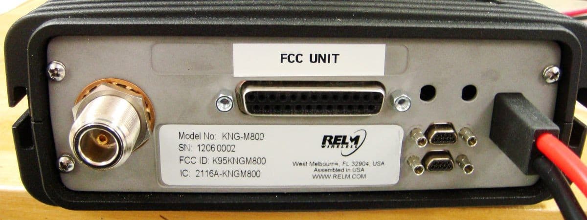
K95KNGM800
Jun 21, 2012MOBILE TRANSCEIVER
Equipment Class
TNB - Licensed Non-Broadcast Station Transmitter
K95KNGP800C
Aug 17, 2011HANDHELD TRANSCEIVER
Equipment Class
TNF - Licensed Non-Broadcast Transmitter Held to Face
K95KNGM500
Dec 07, 2010MOBILE UHF DIGITAL RADIO
Equipment Class
TNB - Licensed Non-Broadcast Station Transmitter