K95DPH51VHF Portable Two-way Radio
BK Technologies, Inc.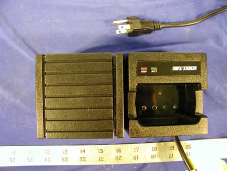
Click to zoom
Application Details
- Equipment Class
- TNF - Licensed Non-Broadcast Transmitter Held to Face
- Date of Grant
- Mar 13, 2003
- Application Purpose
- Original Equipment
- Date of Application
- Dec 08, 2002
- Equipment Note
- VHF Portable Two-way Radio
- Frequency Range
- 148.00000000 - 174.00000000
- Company
- BK Technologies, Inc.
- Country
- United States
Documents & Files
Document Text
Text extracted from the exhibit documents filed with the FCC. Open a document above to read the original.
Users Manual
Specifications are subject to change without notice. BK RADIO Page 1-1 GENERAL INFORMATION 1.1 INTRODUCTION This manual contains information about the physical, mechanical, and electrical characteristics of the BK Radio DPH Flex•Mode Series handheld VHF radios. 1.2 DESCRIPTION The DPH Flex•Mode Series radios are self-contained VHF FM Radios covering the frequency range of 148MHz to 174MHz. The radios are multi-channel and digitally synthesized using a single crystal for frequency control. All models incorporate an EEPROM for the storage of channel frequency, Code Guard, and Dual Tone Multiple Frequency/Automatic Numeric Identifier (DTMF/ANI) encode information. All models also include low-battery and busy-channel indicators. Toggle switches can be programmed to control hi/low transmit power, channel scan, priority scan, repeater talk-around, group scan, or group select. Status and channel information is displayed over a liquid crystal display on keyboard/display models. Connectors are provided on the side of the unit for an external antenna, microphone, speaker, and other optional accessories. A variety of twist-off battery packs are also available. DPH Models DPH Model Number DPH51 (5/2Watts) Options Metal Case 02X Lexan Case 02S General Information DPH Series VHF Radio Specifications are subject to change without notice. Page 1-2 BK RADIO 1.3 TECHNICAL CHARACTERISTICS FREQUENCY: 148-174MHz POWER SUPPLY: One rechargeable nickel-cadmium or nickel-metal-hydride battery pack with temperature sensor or one alkaline battery pack OPERATIONAL FEATURES: Dual Priority Scan Frequency Display Transmit Time-Out Timer User Select Scan Scan Delay Busy Channel Indicate / Lockout Tone Code Guard (CTCSS) DTMF/ANI Encode Digital Code Guard (CDCSS) Interstitial Frequency Capability Nuisance Channel Delete Soft Switches TalkBack Scan Custom Channel Selector User Channel Guard CHANNELS: 400 (25 groups of 16 channels) FREQUENCY SPREAD: 26 MHz with no degradation OPERATING TEMPERATURE: -30° to +60° C PHYSICAL DIMENSIONS Weight: 20 oz. (24 oz. with large battery) 0.6 kilograms (0.7 kg with large battery) Width: 2.55 in. (64.8 millimeters) Depth: 1.5 in. (38.1 mm.) Height: 6.6 in. (167.6 mm.) 7.8 in. (198.1 mm. with large battery) ANTENNA TYPE: Helical wound molded rubber flex (standard) BNC Helical wound molded rubber flex (optional) CHANNEL SPACING: 15/30 and 12.5/25 kHz CHANNEL INCREMENTS: 2.5/6.25/7.5 kHz MAX CURRENT DRAIN: Transmit 5 watt: 1.4 amps Receive: 190 mA Receive standby: 45 mA (battery save off) 15 mA (battery save on) FCC Identification number: K95DPH51 (5/2 Watt Models) DPH Series VHF Radio General Information Specifications are subject to change without notice. BK RADIO Page 1-3 TRANSMITTER 25 / 30 kHz 12.5 / 15 kHz RF OUTPUT POWER DPH51: 5/2 Watts 5/2 Watts OPERATING FREQUENCY SPREAD: 26 MHz 26 MHz SPURIOUS AND HARMONICS: 60 dB 60 dB MODULATION DEVIATION: 5 kHz 2.5 kHz FM HUM AND NOISE: 50 dB 45 dB FREQUENCY STABILITY: ±2.5 PPM ±2.5 PPM AUDIO DISTORTION: 3% 3% AUDIO RESPONSE (per EIA): +1 to -3dB +1 to -3dB MODULATION CHARACTERISTICS: 16K0F3E 11K0F3E 8K10F1E RECEIVER 25 / 30 kHz 12.5 / 15 kHz SENSITIVITY: 12dB SINAD 0.25μV 0.25μV OPERATING FREQUENCY SPREAD: 26 MHz 26 MHz NOISE SQUELCH: 0.18μV 0.18μV SELECTIVITY: 72 dB 60 dB IMAGE AND SPURIOUS RESPONSES: 75dB 75dB INTERMODULATION: 70dB 70 dB AUDIO RESPONSE (per EIA): +1dB / -3dB +1dB / -3dB AUDIO OUTPUT (@ 5% Dist.): 500mW 500mW Accessories A wide variety of optional accessories are available for the DPH handheld radios. Contact your BK Radio dealer for complete information. License Requirements This equipment must be licensed by the Federal Communications Commission (FCC) before it may be used. Your BK Radio dealer can assist you in filing the appropriate application for the FCC, and will program each radio with your authorized frequencies and signaling codes. Service Information If you need service, contact your local BK Radio dealer equipped to service your radio. If you find it impractical to have service performed by your local dealer, contact BK Radio at the address below: BK Radio ATTN: Customer Service 7100 Technology Drive West Melbourne, FL 32904 Voice (800) 422-6281 FAX (321) 953-7986 General Information DPH Series VHF Radio Specifications are subject to change without notice. Page 1-4 BK RADIO BK RADIO 123 456 789 0 * # CLR FCN PRI ENT PRIORITY BUSY CHANNEL LOW BATTERY INDICATOR TRANSMIT INDICATOR ANTENNA HI/LO TRANSMIT POWER SCAN PRIORITY ANTENNA ACCESSORY MOUNT EARPHONE PTT (PUSH TO TALK) SPEAKER MICROPHONE LCD DISPLAY ALPHANUMERIC DISPLAY CHANNEL SELECT ON/OFF VOLUME SQUELCH CODE GUARD G R P PRG TX RX SCNIDCG DPH RADIO WITH KEYBOARD/DISPLAY COVERED OR NOT INSTALLED (REDUCED VIEW) G R P PRGTX RX SCNIDCG TX RX ID CG PROG SCAN 7-SEGMENT DISPLAY BK RADIO CG-OFF- SQVOL 161 2 3 4 5 6 7 8 9 10 11 12 13 14 15 ABC KEYBOARD FIGURE 1-1 CONTROLS
Users Manual
BK RADIO Page 2-1 INSTALLATION AND PROGRAMMING 2.1 GENERAL INFORMATION This section contains information concerning the installation and programming of BK Radio DPH Flex•Mode Series handheld VHF radios. 2.1.1 UNPACKING AND INSPECTING EQUIPMENT Exercise extreme care when unpacking the equipment. Make a visual inspection of the unit for evidence of damage incurred during shipment. If a claim for damage is to be made, save the shipping container to substantiate the claim. The claim should be promptly filed with the transportation company. It would be advisable to retain the container and packaging material after all equipment has been removed in the event that equipment storage or reshipment should become necessary. 2.1.2 BATTERY INSTALLATION A. BK Radio battery packs are available in a variety of sizes and types for special applications. Rechargeable battery packs can be charged separately or while attached to a radio. NOTE: For safety reasons, rechargeable battery packs are shipped uncharged or only partially charged. Therefore, a rechargeable battery pack should be properly charged before use. B. To install the battery, locate the center hub on the radio base and place it in the recess of the battery pack. Position the pack approximately at a 30° offset, seating two metal studs in their recess. Apply upward pressure to the pack while twisting the pack to its final (in line with the radio) position. The metal tab will click, locking the pack in position. C. To remove the battery pack, first turn the radio off. Then, as shown above, push up the metal tab on the side of the case while twisting the battery pack approximately 30° and remove it from the radio. NOTE: All information programmed into the radio is maintained even when the battery pack is removed. D. Periodically check the contacts on the battery pack for dirt that may prevent a good electrical contact with the charging base. WARNING: EXPLOSION HAZARD Do not dispose of a battery pack in fire. An explosion may occur. 2.1.3 ANTENNA INSTALLATION Insert the flexible helical-wound antenna into the radio's antenna connector and turn it clockwise until it is firmly seated. Installation and Programming DPH Series VHF Radio Page 2-2 BK RADIO 2.2 KEYBOARD PROGRAMMING You can program DPH radios in three different ways: A. With a computer, DPH programming software, and an LAA 0725 interface cable. That procedure is not described in this manual. Contact BK Radio for the programming cable, software, and manual required. B. A radio can be programmed with its keypad and a programming plug, LAA0701. That procedure is described in this section. C. You can transfer the programmed settings to another radio of the same frequency band by using a cloning cable. See "Cloning Radio Settings" in section 2.3. 2.2.1 ENTER PROGRAMMING MODE Radios are shipped with a door covering the keypad and display. Before programming, remove the door by removing the battery pack, engaging the door just below the speaker grill, and sliding the door downward. Replace the battery pack. Make sure the battery pack is charged. 1. Insert the programming plug into the side connector of the radio. The push-button master switch will be on the top. NOTE: The cloning cable can be used as a substitute for the programming plug by inserting the end with the push-button master switch into the side connector of the radio. 2. Select a channel group to be programmed (not necessary in 16- channel radios). See "Channel Selection" in section 3.2.4. 3. Press and hold the master switch. 4. While holding the master switch, press and hold the [FCN] key. After approximately three seconds the LCD will display - - - ID. 5. Release the [FCN] key and the master switch. The radio is now in the password entry mode. 6. Enter the six-digit password code for the selected group. Without the correct password code, you cannot proceed with programming. NOTE: New radios shipped from the factory are assigned the password code 000000. While entering the password code the display will not change, but a beep will sound for each key pressed. If the password code is entered incorrectly, the radio will reset to normal operation. Try again, starting at step 2. 7. Press the [ENT] key to proceed to programming mode. The display will change to PRG Ch 00. NOTE: YOUR RADIO MAY HAVE BEEN SET UP TO BLOCK KEYBOARD PROGRAMMING ACCESS TO SOME OR ALL VARIABLES. CONTACT YOUR BK RADIO DEALER IF YOU FEEL YOU NEED ACCESS TO THESE FIELDS. Master Switch Programming Plug 123 456 789 0 * # CLR FCN PRI ENT DPH Series VHF Radio Installation and Programming BK RADIO Page 2-3 2.2.2 GENERAL PERFORMANCE VARIABLES (CHANNEL 0) Channel 0 settings for each group must be programmed separately. NOTE: Settings listed as Group One functions, Group Two functions, and Group Three functions refer to programming function groups, not channel groups. Press the [FCN] key repeatedly to view the settings in Channel 0, then loop back to the Ch 00 entry point. Channel 0 settings include: Group Password Automatic Numeric Identification (ANI) Transmitter Timeout Timer Scan Delay Time Priority 1 Channel Priority 2 Channel Group One functions: 1-12345 Battery Saver Inhibit Group Scan List Transmit on Priority 1 Priority Key Lockout Scan List Lockout Group Two functions: 2-12345 Allow User Code Guard Busy Channel Mode ANI/DTMF Mode Group Three functions: 3-12345 Backlight on Display Change Backlight on Key Press Alphanumeric/Numeric Display Mode Backlight Duration Group Label Installation and Programming DPH Series VHF Radio Page 2-4 BK RADIO 2.2.2.1 Group Password 1. After entering programming mode the display will show PRG Ch 00. 2. Press the [FCN] key. 3. The display will indicate the password for the selected group. 4a. If no change is needed for the group password, press the [FCN] key to advance to the next section. 4b. A new password can be entered by pressing number keys. Press the [ENT] key to store the new password and advance to the next section. 2.2.2.2 Auto…
Text truncated - open the document above for the full version.
Users Manual
OPERATION 3.1 INTRODUCTION This section contains information concerning the operation procedures for the BK Radio DPH Flex•Mode Series handheld VHF radios. Information on installation and programming is contained in Section 2 of this manual. WARNING DO NOT OPERATE THE TRANSMITTER IN CLOSE PROXIMITY TO BLASTING CAPS WARNING DO NOT OPERATE THE RADIO IN AN EXPLOSIVE ATMOSPHERE (PETROLEUM FUELS, SOLVENTS, DUST, ETC.). RF ENERGY EXPOSURE AWARENESS AND CONTROL INFORMATION, AND OPERATIONAL INSTRUCTIONS FOR FCC OCCUPATIONAL USE REQUIREMENTS BEFORE USING YOUR PORTABLE 2-WAY RADIO, READ THIS IMPORTANT RF ENERGY AWARENESS AND CONTROL INFORMATION AND OPERATIONAL INSTRUCTIONS TO ENSURE COMPLIANCE WITH THE FCC’S RF EXPOSURE GUIDELINES. NOTICE: This radio is intended for use in occupational/controlled conditions, where users have full knowledge of their exposure and can exercise control over their exposure to meet FCC limits. This radio device is NOT authorized for general population, consumer, or any other use. This 2-way radio uses electromagnetic energy in the radio frequency (RF) spectrum to provide communications between two or more users over a distance. It uses radio frequency (RF) energy or radio waves to send and receive calls. RF energy is one form of electromagnetic energy; other forms include electric power, radar, sunlight and x-rays. RF energy, however, should not be confused with these other forms of electromagnetic energy, which when used improperly can cause biological damage. Very high levels of x-rays, for example, can damage tissues and genetic material. The energy levels associated with radio waves from portable 2-way radios, when properly used, are not great enough to cause biological damage. Experts in science, engineering, medicine, health and industry work with organizations to develop standards for exposure to RF energy. These standards provide recommended levels of RF exposure for both workers and the general public. These recommended RF exposure levels include substantial margins of protection All 2-way radios marketed in North America are designed, manufactured and tested to ensure they meet government established RF exposure levels. In addition, manufacturers also recommend specific operating instructions to users of 2-way radios. These instructions are important because they inform users about RF energy exposure and provide simple procedures on how to control it. Please refer to the following WEBSITES for more information on what RF energy exposure is and how to control your exposure to assure compliance with established RF exposure limits. http://www.fcc.gov/oet/rfsafety/rf-faqs.html http://www.osha.gov/SLTC/radiofrequencyradiation/index.html FEDERAL COMMUNICATIONS COMMISSION REGULATIONS The FCC rules require manufacturers to comply with the FCC RF energy exposure limits for portable 2- way radios before they can be marketed in the U.S. When 2-way radios are used as a consequence of employment, the FCC requires users to be fully aware of and able to control their exposure to meet occupational requirements. Exposure awareness can be facilitated by the use of a product label directing users to specific user awareness information. Your BK Radio 2-way radio has a RF exposure product label. Also, your BK Radio user manual, or product manual, or separate safety booklet includes information and operating instructions required to control your RF exposure and to satisfy compliance requirements. COMPLIANCE WITH RF EXPOSURE STANDARDS Your BK Radio 2-way radio is designed and tested to comply with a number of national and international standards and guidelines (listed below) for human exposure to radio frequency electromagnetic energy. This radio complies with the IEEE and ICNIRP exposure limits for occupational/controlled RF exposure environment at operating duty factors of up to 50% transmitting and is authorized by the FCC for occupational use only. In terms of measuring RF energy for compliance with the FCC exposure guidelines, your radio radiates measurable RF energy only while it is transmitting (during talking), not when it is receiving (listening) or in standby mode. Note: The approved batteries supplied with this radio are rated for a 5-5-90 duty factor (5% talk-5% listen - 90% standby), even though this radio complies with the FCC occupational RF exposure limits and may operate at duty factors of up to 50% talk. Your BK Radio 2-way radio complies with the following RF energy exposure standards and guidelines: United States Federal Communications Commission, Code of Federal Regulations; 47 CFR §§ 1.1307, 1.1310, 2.1091 and 2.1093 American National Standards Institute (ANSI) / Institute of Electrical and Electronic Engineers (IEEE) C95. 1-1992 Institute of Electrical and Electronic Engineers (IEEE) C95.1-1999 Edition RF EXPOSURE COMPLIANCE AND CONTROL GUIDELINES AND OPERATING INSTRUCTIONS To control your exposure and ensure compliance with the occupational/controlled environment exposure limits always adhere to the following procedures. Guidelines: • Do not remove the RF Exposure Label from the device. • User awareness instructions must accompany device when transferred to other users. • Do not use this device if the operational requirements described herein are not met. Operating Instructions: • Transmit no more than the rated duty factor of 50% of the time. To transmit (talk), push the Push- To-Talk (PTT) button. To receive calls, release the PTT button. Transmitting 50% of the time, or less, is important because this radio generates measurable RF energy exposure only when transmitting (in terms of measuring for standards compliance). • Hold the radio in a vertical position in front of face with the microphone (and the other parts of the radio, including the antenna) at least one inch (2.5 cm) away from the nose. Keeping the radio at the proper distance is important because RF exposures decrease with distance from the antenna. Antenna should be kept away from eyes. • When …
Text truncated - open the document above for the full version.
Users Manual
APX901 User’s Instructions 1. Switch the radio “off”. 2. Insert the 2.5 mm plug of the APX901 into the earphone jack of radio. See diagram for location. 3. Carefully place the collar of the earphone over the ear and position it where it can be comfortably worn. 4. Switch the radio “on” and set the volume control knob to minimal position. 5. Adjust the squelch control until audio can be heard from the earphone. 6. Adjust the volume to a comfortable level. 7. Readjust the squelch. ANTENNA ACCESSORY MOUNT EARPHONE PTT (PUSH TO TALK)
Users Manual
Specifications are subject to change without notice. BK RADIO Page 1-1 GENERAL INFORMATION 1.1 INTRODUCTION This manual contains information about the physical, mechanical, and electrical characteristics of the BK Radio DPH Flex•Mode Series handheld VHF radios. 1.2 DESCRIPTION The DPH Flex•Mode Series radios are self-contained VHF FM Radios covering the frequency range of 148MHz to 174MHz. The radios are multi-channel and digitally synthesized using a single crystal for frequency control. All models incorporate an EEPROM for the storage of channel frequency, Code Guard, and Dual Tone Multiple Frequency/Automatic Numeric Identifier (DTMF/ANI) encode information. All models also include low-battery and busy-channel indicators. Toggle switches can be programmed to control hi/low transmit power, channel scan, priority scan, repeater talk-around, group scan, or group select. Status and channel information is displayed over a liquid crystal display on keyboard/display models. Connectors are provided on the side of the unit for an external antenna, microphone, speaker, and other optional accessories. A variety of twist-off battery packs are also available. DPH Models DPH Model Number DPH51 (5/2Watts) Options Metal Case 02X Lexan Case 02S General Information DPH Series VHF Radio Specifications are subject to change without notice. Page 1-2 BK RADIO 1.3 TECHNICAL CHARACTERISTICS FREQUENCY: 148-174MHz POWER SUPPLY: One rechargeable nickel-cadmium or nickel-metal-hydride battery pack with temperature sensor or one alkaline battery pack OPERATIONAL FEATURES: Dual Priority Scan Frequency Display Transmit Time-Out Timer User Select Scan Scan Delay Busy Channel Indicate / Lockout Tone Code Guard (CTCSS) DTMF/ANI Encode Digital Code Guard (CDCSS) Interstitial Frequency Capability Nuisance Channel Delete Soft Switches TalkBack Scan Custom Channel Selector User Channel Guard CHANNELS: 400 (25 groups of 16 channels) FREQUENCY SPREAD: 26 MHz with no degradation OPERATING TEMPERATURE: -30° to +60° C PHYSICAL DIMENSIONS Weight: 20 oz. (24 oz. with large battery) 0.6 kilograms (0.7 kg with large battery) Width: 2.55 in. (64.8 millimeters) Depth: 1.5 in. (38.1 mm.) Height: 6.6 in. (167.6 mm.) 7.8 in. (198.1 mm. with large battery) ANTENNA TYPE: Helical wound molded rubber flex (standard) BNC Helical wound molded rubber flex (optional) CHANNEL SPACING: 15/30 and 12.5/25 kHz CHANNEL INCREMENTS: 2.5/6.25/7.5 kHz MAX CURRENT DRAIN: Transmit 5 watt: 1.4 amps Receive: 190 mA Receive standby: 45 mA (battery save off) 15 mA (battery save on) FCC Identification number: K95DPH51 (5/2 Watt Models) DPH Series VHF Radio General Information Specifications are subject to change without notice. BK RADIO Page 1-3 TRANSMITTER 25 / 30 kHz 12.5 / 15 kHz RF OUTPUT POWER DPH51: 5/2 Watts 5/2 Watts OPERATING FREQUENCY SPREAD: 26 MHz 26 MHz SPURIOUS AND HARMONICS: 60 dB 60 dB MODULATION DEVIATION: 5 kHz 2.5 kHz FM HUM AND NOISE: 50 dB 45 dB FREQUENCY STABILITY: ±2.5 PPM ±2.5 PPM AUDIO DISTORTION: 3% 3% AUDIO RESPONSE (per EIA): +1 to -3dB +1 to -3dB MODULATION CHARACTERISTICS: 16K0F3E 11K0F3E 8K10F1E RECEIVER 25 / 30 kHz 12.5 / 15 kHz SENSITIVITY: 12dB SINAD 0.25μV 0.25μV OPERATING FREQUENCY SPREAD: 26 MHz 26 MHz NOISE SQUELCH: 0.18μV 0.18μV SELECTIVITY: 72 dB 60 dB IMAGE AND SPURIOUS RESPONSES: 75dB 75dB INTERMODULATION: 70dB 70 dB AUDIO RESPONSE (per EIA): +1dB / -3dB +1dB / -3dB AUDIO OUTPUT (@ 5% Dist.): 500mW 500mW Accessories Use only BK Radio approved supplied or replacement antennas, batteries, and accessories. Use of non- BK Radio approved antennas, batteries, and accessories may exceed the FCC RF exposure guidelines. A wide variety of optional accessories are available for the DPH handheld radios. For a list of BK Radio approved accessories visit the following website : http://www.relm.com License Requirements This equipment must be licensed by the Federal Communications Commission (FCC) before it may be used. Your BK Radio dealer can assist you in filing the appropriate application for the FCC, and will program each radio with your authorized frequencies and signaling codes. Service Information If you need service, contact your local BK Radio dealer equipped to service your radio. If you find it impractical to have service performed by your local dealer, contact BK Radio at the address below: BK Radio ATTN: Customer Service 7100 Technology Drive West Melbourne, FL 32904 Voice (800) 422-6281 General Information DPH Series VHF Radio Specifications are subject to change without notice. Page 1-4 BK RADIO FAX (321) 953-7986 DPH Series VHF Radio General Information Specifications are subject to change without notice. BK RADIO Page 1-5 BK RADIO 123 456 789 0 * # CLR FCN PRI ENT PRIORITY BUSY CHANNEL LOW BATTERY INDICATOR TRANSMIT INDICATOR ANTENNA HI/LO TRANSMIT POWER SCAN PRIORITY ANTENNA ACCESSORY MOUNT EARPHONE PTT (PUSH TO TALK) SPEAKER MICROPHONE LCD DISPLAY ALPHANUMERIC DISPLAY CHANNEL SELECT ON/OFF VOLUME SQUELCH CODE GUARD G R P PRG TX RX SCN ID CG DPH RADIO WITH KEYBOARD/DISPLAY COVERED OR NOT INSTALLED (REDUCED VIEW) G R P PRGTX RX SCN ID CG TX RX ID CGPROG SCAN 7-SEGMENT DISPLAY BK RADIO CG-OFF- SQ VOL 16 1 2 3 4 5 6 7 8 9 10 11 12 13 14 15 ABC KEYBOARD FIGURE 1-1 CONTROLS
Cover Letter(s)
Bay Area Compliance Laboratory Corp. 230 Commercial Street Sunnyvale, CA 94085 Tel: (408) 732-9162 Fax: (408) 732-9164 www.baclcorp.com Dear Sir/Madam, Your website doesn’t work with the text entering response. Therefore, I am submitting the the response as an exhibit to you. Response for reference number: 24868 1. The corrected FCC ID and RF exposure label and label location are in the file “FCC ID & RF Exposure Label.pdf” 2. Please refer to revised file“User Manual 1.doc” page 3 (section of Accessories) and “User Manual 3.doc” (submitted before) page 3 (section of Operating Instructions) for the actual accessories. 3. Please refer to file “device with earphone.pdf” for the device photo corresponding to new exhibit “APX901 User’s Instructions” 4. Please see and “User Manual 3.doc” (submitted before) page 3 (section of Operating Instructions). The device does not have a "phone, held to ear mode". The devise requires the push-to-talk (PTT) button to be pressed to activate the transmitter. It does not have the capability to operate like a typical cellular phone, it operates like a typical two-way land mobile portable walkie-talkie. 5. Please refer to the updated SAR test report “R0210171S.pdf”, section 8.2, page 39-44 for the corrected contour plot. 6. Regarding the time-out-timer (TOT): The TOT is factory set to 225 seconds. It can be reset, by an authorized dealer, in the range from "OFF" to 225 seconds in 15 second adjustment steps. It cannot be reset or changed by the user. The TOT is a feature that limits the transmission to the programmed time for each time the PTT is pressed. It is a common feature used in two-way land mobile products. 7. The new phantom is on order and we will receive it soon. 8. Please refer to the updated “R0210171S.pdf” section 8.1 (last six rows in the table) for the data of held-to-face position. Note: This latest SAR report supercedes the previous SAR reports submitted and that the reason for the revised report was to reformat the SAR data tables to improve the clarity and understanding. Just a reminder from our last communication: 1. Please revised the output power in form 731 and grant to 6.02W 2. Please add one more designator “11K0F3E” to the equipment specification in form 731 and grant. Thank you! Jennifer (for) John
External Photos
BK Radio Inc. FCC ID: K95DPH51 EXHIBIT C - EUT EXTERANL PHOTOGRAPHS Chassis - Front View Chassis - Back View BK Radio Inc. FCC ID: K95DPH51 Chassis - Top View Chassis - Side View BK Radio Inc. FCC ID: K95DPH51 Battery Front Battery Bottom BK Radio Inc. FCC ID: K95DPH51 Battery Top Charger Front BK Radio Inc. FCC ID: K95DPH51 Charger Bottom Charger Top BK Radio Inc. FCC ID: K95DPH51 Radio Interface Box Speaker BK Radio Inc. FCC ID: K95DPH51 Antenna
External Photos
Accessory – Ear Phone Device with Ear Phone
ID Label/Location Info
EXHIBIT A - FCC ID LABELING AND WARNING STATEMENT Proposed FCC ID Label Specifications: Text is black or white in color and is left justified. Labels are silk-screened and shall be “permanently affixed” at a conspicuous location on the EUT. Proposed Label Location on EUT Back Side of the EUT/Proposed ID Label Location
ID Label/Location Info
RF EXPOSURE LABELING AND LOCATION INFORMATION Proposed FCC ID Label Specifications: Text is black or white in color and is left justified. Labels are silk-screened and shall be “permanently affixed” at a conspicuous location on the EUT. Proposed Label Location on EUT Back Side of the EUT/Proposed ID Label Location
ID Label/Location Info
K95DPH51 - RF Exposure & FCC ID Label Location K95DPH51 - RF Exposure & FCC ID Label
Internal Photos
BK Radio Inc. FCC ID: K95DPH51 EXHIBIT C - EUT INTERANL PHOTOGRAPHS Main Board - Component View Main Board - Solder View BK Radio Inc. FCC ID: K95DPH51 Antenna Connection Transceiver Board Component View BK Radio Inc. FCC ID: K95DPH51 Transceiver Board Solder View Transceiver Component View BK Radio Inc. FCC ID: K95DPH51 Transceiver Solder View
Operational Description
BK RADIO Page 4-1 THEORY OF OPERATION 4.1 INTRODUCTION This section contains the theory of operation for the DPH Flex•Mode radio. To help you understand the operation of the equipment, refer to the schematic diagrams in Section VI of this manual. 4.2 EQUIPMENT DESCRIPTION The DPH Flex•Mode radio is a self-contained VHF FM radio operating in the 148 MHz to 174 MHz band. The radio is digitally synthesized and uses a single crystal for frequency control. An EEPROM is incorporated for the storage of channel frequency, Code Guard™ values, Automatic Numeric Identifier (ANI), hardware tuning, and other operating information. Connectors are provided on the side of the radio for the external antenna, microphone, speaker, and other optional accessories. Twist-off battery packs are also available. The 16 channels are fully programmable. The radio is shipped with stop pins so that the channel selector switch can be moved to limit the number of positions to any value. 4.3 THEORY OF OPERATION Circuitry for the DPH Series radio comprises five major circuits: • The RECEIVER, which consists of RF preselectors, RF amplifier, mixer, IF filters, IF amplifiers, FM IF IC, and noise squelch circuitry. • The TRANSMITTER, which consists of a power amplifier, harmonic filter, antenna switch, and power control circuitry. • The SYNTHESIZER, which consists of a voltage controlled oscillator (VCO), VCO buffer, prescaler buffer, prescaler, synthesizer IC, reference oscillator, loop filter, and acquisition aid bit circuit. • The SYSTEMS area, which consists of a microprocessor, microprocessor oscillator, EEPROM, signaling and switching, front-end tuning amplifier, 5V and 8.2V regulators, transmitter audio processing, deviation compensation, squelch threshold circuitry, and receiver audio processing. • The Digital Signal Processing (DSP) area, which consists of a Digital Signal Processor, Flash Memory, CODEC, TCXO, 1.8V and 3.3V regulators. 4.3.1 Receiver The receiver is a dual-conversion design with intermediate frequencies of 16.9 MHz and 455kHz. RF signals received at the antenna pass through the antenna switch and front end. The front end consists of an amplifier and two microprocessor-tuned bandpass filters. The front end amplifies the receive frequency and attenuates image, half IF, and other frequencies that degrade receiver performance. RF signals from the front end enter a mixer that converts them to 16.9 MHz. The 16.9 MHz IF signal passes through two crystal filters that provide adjacent channel selectivity. The IF amplifier then amplifies the signal and couples it to the 455 kHz IF integrated circuit. The 455 kHz IF IC consists of a mixer, limiter, demodulator, and squelch circuit. The 16.9 MHz signal enters the mixer and is converted to a 455 kHz IF signal. A ceramic filter at 455 kHz provides more adjacent channel selectivity. The signal is then amplified by the limiter and demodulated. Audio processing is then done on the options board. Filtered audio noise is used to provide a squelch indication. Theory of Operation DPH Series VHF Radio Page 4-2 BK RADIO A. RF Preselectors The preselectors provide greater than 75 dB of attenuation at the image frequency. Both bandpass filters are varactor tuned, which allows a wide frequency spread. Overall, the preselectors exhibit a bandwidth of 4.5 MHz. The preselectors consist of L2, L3, L4, L5, and associated circuitry. Figure 4-1 Receiver block diagram B. RF Preamplifier The RF amplifier is a single-transist…
Text truncated - open the document above for the full version.
Contact Information
Applicant
Brian W. Jones(VP Engineering)
Technical Contact
Bay Area Compliance LaboratoryJohn Chan
[email protected](408) 732 9162
230 Commercial Street · Sunnyvale, California · United States
Non-Technical Contact
Bay Area Compliance Laboratory Corp.Jennifer Song
[email protected](408) 732 9162
Test Firm
Bay Area Compliance LaboratoryJohn Chan
Technical Specifications
| # | Rule Parts | Frequency Range | Power Output | Emission | Tolerance |
|---|---|---|---|---|---|
| 4 | 90.210,22,74,8 | 148 MHz - 174 MHz | 6.4 W | 11K0F3E | 5 ppm |
Other Applications from BK Technologies, Inc.

K95BKR9000-2
May 29, 2023Multi-Band Portable Radio VHF/UHF/700/800
Equipment Class
DTS - Digital Transmission System
K95BKR5000-V
Apr 15, 2020Handheld Transceiver
Equipment Class
TNF - Licensed Non-Broadcast Transmitter Held to Face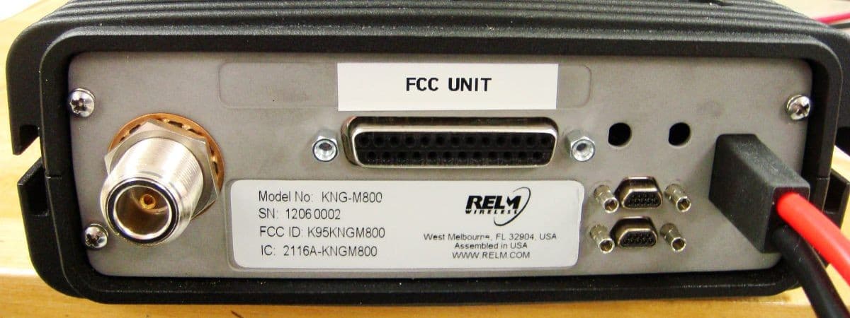
K95KNGM800
Jun 21, 2012MOBILE TRANSCEIVER
Equipment Class
TNB - Licensed Non-Broadcast Station Transmitter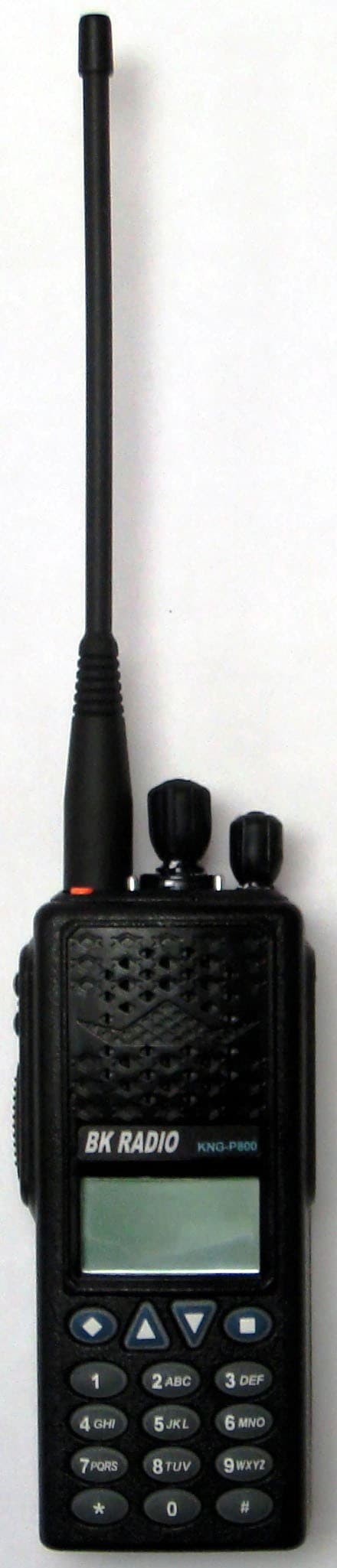
K95KNGP800C
Aug 17, 2011HANDHELD TRANSCEIVER
Equipment Class
TNF - Licensed Non-Broadcast Transmitter Held to Face
K95KNGM500
Dec 07, 2010MOBILE UHF DIGITAL RADIO
Equipment Class
TNB - Licensed Non-Broadcast Station Transmitter