K95GMH599VHF Mobile Transceiver
BK Technologies, Inc.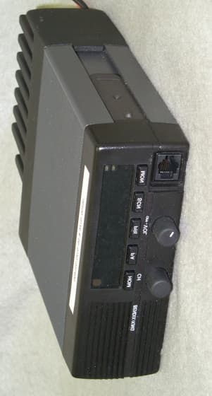
Click to zoom
Application Details
- Equipment Class
- TNB - Licensed Non-Broadcast Station Transmitter
- Date of Grant
- Jun 28, 2000
- Application Purpose
- Original Equipment
- Date of Application
- May 23, 2000
- Equipment Note
- VHF Mobile Transceiver
- Frequency Range
- 136.00000000 - 174.00000000
- Company
- BK Technologies, Inc.
- Country
- United States
Documents & Files
Document Text
Text extracted from the exhibit documents filed with the FCC. Open a document above to read the original.
Users Manual
Specifications are subject to change without notice. BK RADIOPage 1-1 SECTION I GENERAL INFORMATION 1.1INTRODUCTION This manual contains information about the physical, mechanical, and electrical characteristics of the BK Radio GMH Flex•Mode Series mobile VHF radios. 1.2DESCRIPTION The GMH Flex•Mode Series radio is a mobile VHF FM transceiver covering the frequency range of 136MHz to 174MHz. The GMH features an alphanumeric eight-character vacuum fluorescent display, allowing the channels to be named for easy user recognition. An arrow on the vacuum fluorescent display points to each front mounted push button that is active. The five push buttons can be programmed with the following functions: Standard FunctionsOptional Functions MON Monitor Squelch Noise TA Repeater Talk Around GSC Group Scan SCN Channel Scan CG Code Guard Disable SQL Squelch Adjust PRI Priority Scan GRP Channel Group ACC Accessory 1 PA Public Address SPK External Speaker ACC Accessory 2 HOM Home Channel NXT Next Scan Channel ACC Accessory 3 LPW Low Power Select The microphone connector provides an RS-232 interface for control by a keypad microphone, and for dealer programming of alphanumeric labels, push button functions, channel frequencies, Code Guard™ values, and Dual Tone Multiple Frequency/Automatic Numeric Identifier (DTMF/ANI) encode information. Figure 1-1 CONTROLS General InformationGMH Series VHF Radio Specifications are subject to change without notice. Page 1-2BK RADIO 1.3TECHNICAL CHARACTERISTICS FREQUENCY RANGE136–174MHz CHANNELS320 (20 groups of 16 channels) OPERATING VOLTAGE 13.6 Vdc Negative ground OPERAT ION AL FE AT URES Fluorescent Alphanumeric DIsplayIncluded Enhanced User CGProgrammable Code Guard Squelch (CTCSS & CDCSS)Programmable Time Out TimerProgrammable Frequency DisplayProgrammable User Select ScanProgrammable Dual Priority ScanProgrammable Busy Channel LockoutProgrammable Busy Channel IndicatorProgrammable DTMF ANIProgrammable Talk-back ScanProgrammable Interstitial Frequency CapabilityProgrammable PRIMARY POWER INPUT Receive @13.8V1.0 Amperes Transmit @ 13.6V 16.0 Amperes Standby @ 13.8V5 Amperes OPERATING TEMPERATURE-30° to +60° C PHYSICAL DIMENSIONS Width6 in. Depth9.38 in. Height2.12 in. Weight5 lbs. FREQUENCY STABILITY ± 2.5 PPM CHANNEL SPACING25/30 kHz and 12.5/15 kHz CHANNEL INCREMENTS6.25/2.5 kHz ANTENNA CONNECTOR MINI UHF FCC IDENTIFICATION NUMBERPending GMH Series VHF RadioGeneral Information Specifications are subject to change without notice. BK RADIOPage 1-3 TRANSMITTER` 25/3012.5/15 RF OUTPUT POWER15 to 50 Watts15 to 50 Watts OPERATING FREQUENCY SPREAD38 MHz38 MHz MODULATION DEVIATION ± 5 kHz ± 2.5 kHz SPURIOUS AND HARMONICS80dB80dB HUM AND NOISE50dB45dB AUDIO DISTORTION3%3% ANTENNA OUTPUT IMPEDENCE50 Ohms50 Ohms AUDIO RESPONSE+1 to –3dB +1 to –3dB RECEIVER 25/3012.5/15 SENSITIVITY: 12dB SINAD0.28 μ V0.28 μ V FREQUENCY SPREAD38 MHz38 MHz SELECTIVITY75dB63dB SPURIOUS INCLUDING IMAGE80dB80dB INTERMODULATION75dB63dB MAX AUDIO OUTPUT (5% DISTORTION)4 Watts4 Watts AUDIO FREQUENCY LOAD3.2 Ohms3.2 Ohms INPUT IMPEDENCE50 Ohms50 Ohms AUDIO RESPONSE+1 to –3dB +1 to –3dB HUM AND NOISE-45 dB-45 dB 1.4ACCESSORIES A wide variety of optional accessories are available for the GMH mobile radios. Contact your BK Radio dealer for complete information. 1.5LICENSE REQUIREMENTS This equipment must be licensed by the Federal Communications Commission (FCC) before it may be used. Your BK Radio dealer can assist you in filing the appropriate application for the FCC, and will program each radio with your authorized frequencies and signaling codes. 1.6SERVICE INFORMATION If you need service, contact your local BK Radio dealer equipped to service your radio. If you find it impractical to have service performed by your local dealer, contact BK Radio at the address below: BK Radio, Inc. ATTN: Customer Service 7505 Technology Drive West Melbourne, FL 32904 Voice(800) 422-6281 FAX (407) 953-7986
Users Manual
BK RADIOPage 2-1 SECTION II INSTALLATION AND PROGRAMMING 2.1GENERAL INFORMATION This section contains information concerning the installation and programming of BK Radio GMH Series radios. 2.1.1Unpacking and Inspecting Equipment Exercise extreme care when unpacking the equipment. Make a visual inspection of the unit for evidence of damage incurred during shipment. If a claim for damage is to be made, save the shipping container to substantiate the claim. The claim should be promptly filed with the transportation company. It would be advisable to retain the container and packaging material after all equipment has been removed in the event that equipment storage or reshipment should become necessary. 2.1.2Installation Plan your installation carefully. Locate the radio and microphone within easy reach, giving the operator a clear view of the display. Do not locate the radio or microphone in a position that interferes with safe operation of the vehicle. Once the equipment location is chosen, determine the best routing for cables and wires to connect the system. Use a rubber grommet to protect the wires when passing through sheet metal. Avoid any route that subjects the wire to pinching, cutting, or high heat from the engine or other vehicle component. The radio must be used with a 12 volt, NEGATIVE GROUND electrical system. Refer to Figure 2-1. 1. Crimp the fuse holder in line with the red power lead as close to the battery as possible. 2. Connect the red power lead to the vehicle battery POSITIVE terminal. Using other positive voltage points in the vehicle is not recommended. 3. Connect the black lead to a good ground point on the vehicle chassis. Connection to the negative battery terminal is not recommended. 4. Mount the antenna carefully. Follow the instructions supplied with the antenna kit. Route the coax cable to the radio mounting location. 5. Fasten the mounting bracket securely to the desired location. 6. Mount the microphone clip securely to the desired location. The microphone hanger clip must be grounded for proper radio operation. Use the supplied ground wire if needed. 7. Mount any approved accessory speakers and route the wires to the rear of the radio bracket. 8. Connect the power lead, antenna connector, and accessory wires to the rear of the radio. 9. Place the radio in the mounting bracket, adjust to the proper mounting angle, and thread in the two side mounting knobs until the unit is secure. NOTE: Option A and B connections are logic level outputs. Consult your BK Radio dealer before connecting accessories to these pins. Installation and ProgrammingGMH Series VHF Radio Page 2-2BK RADIO FIGURE 2-1 INSTALLATION HANG -UP CLI P. FO R PRO PER O PERATI O N, THE RADIO M UST BE SET UP U P F O R "O F F -H O O K W H E N M O N I TOR HI G H". C O N TAC T YO UR BEN DIX/KI NG TH E H A N G -U P CLI P. FO R PRO PER O PERATIO N , THE RADIO M UST BE SET CODE G UARD OPERATI ON. USE GROUND WI RE (I TE M 1 3 ) IF N E E D E D . TH E S E M I C RO PHO N ES SUPPLY AN O PEN M O N I TO R SIG N AL W HEN I N THE M IC RO PHO N E M O DEL # LAA 0276, LAA 0281 DEALER FOR PROGRAMMING CHANGES. TH E S E M I C RO PHO N ES SUPPLY A G RO UN DED M O NI TO R SIG N A L W H EN I N M IC RO PHO N E M O DEL # LAA 0285, LAA 0282- R A D I O PROGRAMMING DI FFERS DEPEN DING O N M I CROPHONE M ODEL USED: - TH E M I CRO PHONE HANG -UP CLI P M UST BE G RO UNDED FO R PROPER * I M PO RTAN T- READ BEFO RE O PERATI NG M I CRO PHO NE * GROUND WI RE, HANG UP C LI P 155-02220-0000 13 I TE M 13 D EC A L SET 057-05418-0000 12 HAN G -UP C LI P * MICROPHONE MIC PLUG C A BLE SH ELL 11 030-01448-0000 POWER ( J1 3) CONNECTOR MI CROPHONE TH I S D W G I TEM S 8 AN D 9 ARE I NC LUDED FOR APPLI CATIONS NOT REQUIRI NG A FRO NT SEE BELO WSEE BELO W QTY 2QTY 4 REM ARKS I N STA LLA TIO N K I T - PARTS I NCLUDED (2 R E Q ' D) I TE M 3 GROUND C H A SSIS BATTERY VEHIC LE BATTERY AS PO SSI BLE I NSTALL FUSE HO LDER AS C LO SE TO C RIM P AREA CRI MP AREA (J 1 7 ) CONNECTOR A C C ESSO R Y (J 4 ) CONNECTOR ANTENNA (J 1 6 ) JA C K SPEA KER CONNECTOR POWER (+ ) (-) ITE M 6 ITM 5 RED BLAC K ITM 5 654321 987654321 EXTERN AL C O N NEC TIO NS FUSE HO LD ER D ETAI L MI C C O RD DETAI L (4 R E Q ' D) I TE M 4 (4 PLC S.)NO. 26 DRI LL 0.147 S C H E M A TIC REC O M M EN DED HO LE PATTERN I TE M 2 PA RT O F M I C ROPHO NE 10 030-03194-0000 9 PIN MALE CONNECTOR 9 088-02593-0000 M IC C O VER8 088-02594-0001 GROMMET7 036-00041-0000 FUSE 15A, 32V, FA ST BLO W6 033-00226-0000 FUSE HO LD ER5 1 55-02 717 -00 00 PO W ER C O RD A SSY.4 089-07072-0012 SELF TAPPING SC REW , # 10 M OUNTI NG KNOB 090-00941-0000 3 MOUNTI NG BRACKET 047-09806-0001 2 EM H/EM V I N STA LLATI ON I NSTRUCTI ONS 006-01234-0003 1 D ESC RI PTIO N PART N UM BER I TEM 96 5 1 GND 3.2 0HM AUDI O OUT LO AUDI O OUT HI 15A -EM V BLAC KRED J13 J17 (9 PIN) MI C HI MI C LO BU F D I SC OPT APTTSW A +MONOPTI ON B REM O TE SPKR J16 J4 TO ANTENNA EM H/EM V M O BILE U N IT 6 1 PRO GMONMI C HI MI C LO PTTSW A+ MOUNTED MI C RO PHO N E. THEY ARE TO BE USED TO SEAL O FF THE UNUSED MIC OPENING. F O R "O F F -H O O K WHEN MONI TO R LO W ". C O NTAC T YO UR BEND I X/KI NG D EALER FO R THE REQ UI RED PROGRAMMI NG CHANG ES. 10 030-03246-0000 15 PIN M ALE C O NNEC TO R OR EM V-O LDER EM H & EM V-NEW ER 1 5 15 11 6 10 OR J17 (15 PI N) -1 O P T B -2 N .C . -3 REM O TE SPKR -4 O P T C -5 SW A + -6 C HASSIS GND -7 M IC LO -8 MON -9 PRO G -10 O PT A -11 M IC HI -12 PTT -13 BUF D ISC -14 N.C . -15 REM O TE S P K R G N D + + B A TTER YCHASSI S GROUND 20A - EM H 7 036-00037-0000 FUSE 20A, 32V, SLO W BLO W EM V EM H OR GMH Series VHF RadioInstallation and Programming BK RADIOPage 2-3 2.2KEYBOARD PROGRAMMING GMH Series radios can be programmed in three different ways: A. With a computer, GMH tuning software, and an LAA 0725 interface cable. That procedure is not described in this manual. B. With the optional LAA 0290 keyboard microphone. That procedure is described in this section. C. With an LAA 0700 cloning cable, clone programmed s…
Text truncated - open the document above for the full version.
Users Manual
BK RADIOPage 3-1 SECTION III OPERATION 3.1 INTRODUCTION This section contains information concerning the operation procedures of the GMH Series radio. Information on programming and installation is contained in Section 2 of this manual. 3.1.1 Safety precautions A. Do not operate the transmitter in close proximity to blasting caps. B. Do not operate the radio in an explosive atmosphere (petroleum fuels, solvents, dust, etc.). C. Do not operate the transmitter if a person outside the vehicle is within two feet of the antenna or touching the antenna. D. Do not install the radio in a closed compartment that contains an LP gas container or its fittings. E. The radio must be properly grounded. F. The equipment must be installed and serviced by a qualified technician. 3.2BASIC OPERATION 3.2.1 Receive T URN POWER ON by turning the Volume knob clockwise past the OFF detent. The radio will beep, indicating that it has passed its self test and is operational. S ET VOLUME by pressing the MON button to hear squelch noise. Turn the Volume knob to set a comfortable volume level. Press the MON button again to stop squelc h no ise. S ELECT A CHANNEL GROUP (if applicable) by pressing the GRP button and turning the Channel Select knob. Press the GRP button again to return to channel select mode. See “GRP” on page 3-5. S ELECT A CHANNEL by turning the Channel Selector knob. After reaching the highest number, the radio wraps to channel 1. The display can show channel numbers (numeric mode), channel labels (alphanumeric mode), or receive and transmit frequencies. The display mode and channel labels are programmed by the technician along with group labels (if applicable) and channel frequencies. The display shows slightly different indications during Channel Scan and Priority Scan operation in alphanumeric and numeric modes. OperationGMH Series VHF Radio Page 3-2BK RADIO 3.2.2 Transmit P RESS THE PTT (Push To Talk) switch on the microphone. The TX annunciator appears on the display and the red Transmit indicator glows while the PTT is pressed. Talk in a normal voice with the microphone approximately one to two inches from your mouth. Release the PTT switch to stop transmitting. If the TX annunciator does not appear and a tone is heard, you are on a receive-only channel or the channel is busy (if Busy Channel Lockout is enabled). Turn the Channel Select knob to an authorized transmit channel or wait until the channel is clear (if Busy Channel Lockout is installed). If the length of the message exceeds the preset time-out timer setting, the transmitter automatically shuts off and a tone sounds. To continue the transmission, release the PTT switch, and then press it again and continue talking. 3.2CODE GUARD OPERATION Code Guard TM allows one radio or group of radios to be selectively called within a system. If the radio has been programmed with Code Guard, use the following receive and transmit instructions. 3.2.1 Code Guard Receive T URN POWER ON by turning the Volume knob clockwise past the OFF detent. The radio will beep, indicating that it has passed its self test and is operational. S ET VOLUME by pressing the MON button to hear squelch noise. Turn the Volume knob to set a comfortable volume level. Press the MON button again to stop squelc h no ise. S ELECT A CHANNEL GROUP (if applicable) by pressing the GRP button and turning the Channel Select knob. Press the GRP button again to return to channel select mode. See “GRP” on page 3-5. S ELECT A CHANNEL by turning the Channel Selector knob. After reaching the highest number, the radio wraps to channel 1. P RESS THE CG BUTTON to disable or enable Code Guard operation. An arrow on the display points to the CG button when Code Guard is disabled. When Code Guard is enabled, a message is heard only when the proper Code Guard is received. OperationGMH Series VHF Radio BK RADIOPage 3-3 3.2.2 Code Guard Transmit M ONITOR THE CHANNEL , before transmitting on Code Guard channels, by lifting the microphone off hook or pressing the MON button. Listen to the channel for a few seconds to ensure that no communications are occurring on the channel. P RESS THE PTT (Push To Talk) switch on the microphone. The TX annunciator appears on the display and the red Transmit indicator glows while the PTT is pressed. Talk in a normal voice with the microphone approximately one to two inches from your mouth. Release the PTT switch to stop transmitting. H ANG UP THE MICROPHONE when finished. If you pressed the MON button to monitor the channel, press it again after the transmission to return to Code Guard operation. 3.3Button Functions When the radio is installed, labels are placed on the front push buttons to indicate their functions. An arrow on the display points to each front mounted push button that is active. The five push buttons can be programmed w ith the follow ing functions: Standard FunctionsOptional Functions MON Monitor Squelch Noise TA Repeater Talk Around GSC Group Scan SCN Channel Scan CG Code Guard Disable SQL Squelch Adjust PRI Priority Scan GRP Channel Group ACC Accessory 1 PA Public Address SPK External Speaker ACC Accessory 2 HOM Home Channel NXT Next Scan Channel ACC Accessory 3 LPW Low Power Select Each of these controls is described in the following sections. MONMonitor Squelch Noise Press the MON button to start or stop monitoring squelch noise. This allows you to set a comfortable volume level. SCNChannel Scan Press the SCN button to start or stop scanning channels in the scan list. Scan operation occurs only while the radio is not transmitting. To add or delete the current channel from the scan list, press the SCN button and hold it down for 1 second or more. See “Channel Scan” on page 3-7. PRIPriority Scan Press the PRI button to start or stop priority scanning. The PR annunciator and the flashing SCN annunciator appear on the display. To make the current channel the fixed priority channel, press the PRI button and hold it down for 1 second or more. See “Prior…
Text truncated - open the document above for the full version.
Users Manual
BK RADIOPage 4-1 SECTION IV THEORY OF OPERATION 4.1INTRODUCTION This section contains a description of equipment and a theory of operation for the BK Radio GMH Series mobile radio. To aid in understanding the operation of the equipment, schematic diagrams are found in Section VI of this manual. 4.2EQUIPMENT DESCRIPTION The BK Radio GMH Series radio comprises the following sub-assemblies: 4.2.1System Board This sub-assembly consists of core microprocessor, synthesizer, regulation, and switching circuitry. A casting is used to shield the synthesizer area. 4.2.2RX/TX Board This sub-assembly consists of the RX/TX antenna switch, the receiver circuitry from the front-end through the discriminator, and the low level transmitter line up. 4.2.3High Level Power Amplifier Board This sub-assembly consists of the final two stages of the transmitter power amplifier, harmonic filter, and directional coupler. 4.2.4Options Board This sub-assembly consists of receive and transmit audio chains, and interfaces with both the system board and the control board. 4.2.5Control board This sub-assembly consists of a control head microprocessor, switching regulator, display driver, and audio power amplifier. It interfaces with the front panel and accessory connector. 4.2.6VCO Board The VCO board is a separate assembly that resides in its own shielded enclosure and interconnects with the system board and RX/TX board. Theory of OperationGMH Series VHF Radio Page 4-2BK RADIO 4.3THEORY OF OPERATION 4.3.1System board System board functions include: 1. Core Microprocessor 2. Regulation: 5.0, 8.6, 9.6, and 20.0 Volts 3. Synthesizer 4. Squelch Detection 5. CTCSS/CDCSS Decode 6. Power Control 4.3.1.1 Microprocessor Control The core microprocessor (U507) communicates with the control head microprocessor and controls radio functions such as loading the synthesizer, adjusting the deviation and receiver tuning, and CTCSS/CDCSS detection. An EEPROM is used to store calibration and tuning data unique to each radio. A 32.768 kHz crystal is used as a clock for the core microprocessor. Various transistors provide level interfaces and current capability. 4.3.1.2 Regulation: 5.0, 8.6, 9.6, and 20.0 Volts U502 and associated circuitry comprise a 9.6 volt low noise feedback regulator for use by noise-sensitive analog circuitry on the system and RX/TX boards. A low battery indication is derived by sensing the error control voltage of this regulator. U601 and associated circuitry provide a second level of regulation to supply the VCO and synthesizer with 8.6 volts and 5.0 volts. U504 is the 5 volt supply for the core of the radio. The microprocessor drives a FET amplifier (Q503) tied to a voltage doubler. This forms a 20 volt switching regulator which is regulated by error amplifier U502 which controls the gain on the FET. 4.3.1.3 Synthesizer Synthesizer IC - U604 forms the main synthesizer IC which contains three programmable CMOS dividers and a sample-and–hold phase detector. The first divider (divide-by-R) divides the reference oscillator down to a frequency which is used as a reference by the sample-and-hold phase detector. The second divider (divide-by-N) divides the output of the Prescaler down to a frequency which is equal to the divided down reference frequency when the loop is locked. The third divider (divide-by-A) controls the modulus control line of the Prescaler. The sample-and-hold phase detector provides a DC voltage that is proportional to the phase error between the divided down reference frequency and the divided down carrier frequency. This voltage is fed through the loop filter to the VCO and adjusts the VCO frequency to maintain phase lock between the divided down frequencies. GMH Series VHF RadioGeneral Information BK RADIOPage 4-3 Prescaler - The prescaler U602 is the first divider in the feedback path of the synthesizer. It divides the RF signal to a frequency which can be processed by the following CMOS dividers. The prescaler is a dual modulus type which allows the division ratio to be set by the synthesizer to either divide-by-128 (modulus control line high) or divide-by-129 (modulus control line low). This capability allows the channel spacing to be determined by the divided down reference frequency and not a multiple thereof. Reference Oscillator - The Reference Oscillator provides the frequency reference from which the receiver and transmitter injection signals are synthesized. The oscillator frequency is controlled by the crystal Y601 which operates in the parallel resonant mode. The core microprocessor uses temperature sensor U607 to measure the temperature of the crystal and changes the bias on varactor CR602 accordingly, to compensate the crystal to less than ±2.5 ppm tolerance. The varactor provides a means for modulating the reference oscillator to improve the synthesizer frequency response for low frequency modulation. Loop Filter - The Loop Filter removes noise and unwanted frequency components from the output of the sample-and-hold phase detector which otherwise would modulate the VCO. In addition, it employs a multiple filter bandwidth design which allows fast response during frequency changes (such as in channel scan) without degrading the noise and spurious performance of the receiver during steady state receive and transmit conditions. The filter bandwidth is switched to a wide condition when the LATCH line pulses high for approximately 6 msec during a frequency change. This allows the new frequency to be reached quickly. When the LATCH line to returns to a low state, the filter bandwidth changes to a narrow condition and provides for good noise and spurious performance. Different filter bandwidths are used for transmit and receive to provide better hum and noise performance in transmit and faster response time in receive. This is accomplished by changing the filter bandwidth to a narrower value when the RX/-TX line goes low during transmit. Offset D/A – U603 and associated resistors form a seri…
Text truncated - open the document above for the full version.
Users Manual
BK RADIOPage 5-1 SECTION V MAINTENANCE 5.1INTRODUCTION This section contains test and alignment procedures for an operational GMH Series mobile radio. This section also contains disassembly and alignment procedures. An understanding of the theory of operation is recommended before maintenance is attempted. 5.1.1Test Equipment Required RF Signal GeneratorHP8640 or equivalent Distortion AnalyzerHP334A or equivalent Power MeterHP435B with 30 dB pad or equivalent Service MonitorCushman 4000 Radio Communications Test Set or equivalent Digital MultimeterIBM PC or equivalent, with 256K memory and an RS-232 serial port LAA0705 or LAA 0725 programming cable GMH Editor Software GMH Tool/Cable KitLAA 0621, P/N 050-03152-0000 This tool kit consists of the following parts: Heatsink076-01475-0000 Spanner Tool076-01451-0000 GMH RF Test Cable155-02773-0000 2 X 6 Test Cable155-02705-0000 Flex Cables (2 included)155-02705-0000 2 X 5 Test Cable (2 included)155-02622-0000 Audio Cable155-02269-0000 5.2OVERHAUL 5.2.1Visual Inspection This section contains instructions to assist in determining, by inspection, the condition of GMH assemblies. Defects resulting from wear, physical damage, deterioration, or other causes can be found by these inspection procedures. To aid inspection, detailed procedures are arranged in alphabetical order. 5.2.1.1 Capacitors, Fixed Inspect capacitors for case damage, body damage, and cracked, broken, or charred insulation. Check for loose, broken, or corroded terminal studs, lugs, or leads. Inspect for loose, broken, or improperly soldered connections. On chip caps be especially alert for hairline cracks in the body and broken terminations. MaintenanceGMH Series VHF Radio Page 5-2BK RADIO 5.2.1.2 Capacitors, Variable Inspect trimmers for chipped and cracked bodies, damaged dielectrics, and damaged contacts. 5.2.1.3 Chassis Inspect the chassis for deformation, dents, punctures, badly worn surfaces, damaged connectors, damaged fastener devices, loose or missing hardware, component corrosion, and damage to the finish. 5.2.1.4 Connectors Inspect connectors for broken parts and other irregularities. Inspect for cracked or broken insulation and for contacts that are broken, deformed, or out of alignment. Also, check for corroded or damaged plating on contacts and for loose, improperly soldered, broken, or corroded terminal connections. 5.2.1.5 Covers and Shields Inspect covers and shields for punctures, deep dents, and badly worn surfaces. Also, check for damaged fastener devices, corrosion, and damage to finish. 5.2.1.6 Flex Circuits Inspect flex circuits for punctures and badly worn surfaces. Check for broken traces, especially near the solder contact points. 5.2.1.7 Fuse Inspect for blown fuse and check for loose solder joints. 5.2.1.8 Insulators Inspect insulators for evidence of damage, such as broken or chipped edges, burned areas, and presence of foreign matter. 5.2.1.9 Jacks Inspect all jacks for corrosion, rust, deformations, loose or broken parts, cracked insulation, bad contacts, or other irregularities. 5.2.1.10Resistors, Fixed Inspect the fixed resistors for cracked, broken, blistered, or charred bodies and loose, broken, or improperly soldered connections. On chip resistors, be especially alert for hairline cracks in the body and broken terminations. 5.2.1.11RF Coils Inspect all RF coils for broken leads, loose mountings, and loose, improperly soldered, or broken terminal connections. Check for crushed, scratched, cut, or charred windings. Inspect the windings, leads, terminals, and connections for corrosion or physical damage. Check for physical damage to forms and tuning slug adjustment screw s. 5.2.1.12Terminal Connections, Soldered 1. Inspect for cold-soldered or resin joints. These joints present a porous or dull, rough appearance. Check for strength of bond using the points of a tool. 2. Examine the terminals for excess solder, protrusions from the joint, pieces adhering to adjacent insulation, and particles lodged between joints, conductors, or other components. 3. Inspect for insufficient solder and unsoldered strands of wire protruding from conductor at the terminal. Check for insulation that is stripped back too far from the terminal. GMH Series VHF RadioMaintenance BK RADIOPage 5-3 4. Inspect for corrosion at the terminal. 5.2.2Cleaning A. Using a clean, lint-free cloth lightly moistened with soap and water only, remove the foreign matter from the equipment case and unit front panel. Wipe dry using a clean, dry, lint-free cloth. B. Using a hand controlled dry air jet (not more than 15psi), blow the dust from inaccessible areas. Care should be taken to prevent damage by the air blast. C. Clean the receptacles and plugs with a hand controlled dry air jet (not more than 25psi), and a clean, lint-free cloth lightly moistened with soap and water only. Wipe dry with a clean, dry, lint-free cloth. 5.2.3Repair This section describes the procedure along with any special techniques for replacing damaged or defective components. 5.2.3.1 Connectors When replacing a connector, refer to the appropriate PC board assembly drawing and follow the notes to insure correct mounting and mating of each connector. 5.2.3.2 Crystal The use of any other than a BK Radio crystal is considered an unauthorized modification. 5.2.3.3 Diodes Use long nose pliers as a heat sink under normal soldering conditions. Note the diode polarity before removal. 5.2.3.4 Integrated Circuits Refer to Appendix A for removal and replacement instructions. 5.2.3.5 Wiring/Coaxial Cable When repairing a wire that has broken from its terminal, remove all old solder and pieces of wire from the terminal, restrip the wire to the necessary length and resolder the wire to the terminal. Replace a damaged wire or coax with one of the same type, size, and length. 5.3DISASSEMBLY & ASSEMBLY The GMH radio has three major assemblies which contain the following circuit boards: • Control Head Assembly (at the front of the radio) S…
Text truncated - open the document above for the full version.
Users Manual
BK RADIOPage 6-1 SECTION VI ILLUSTRATED PARTS LIST 6.1INTRODUCTION This section helps you identify parts used in BK Radio’s GMH mobile Transceiver. It includes Replacement Parts Lists for all major assemblies arranged from the Final Assembly down to an individual part level. Each List is followed by the corresponding Assembly Drawing (if required), Schematic Diagram and Parts Placement. Parts itemized in the various lists meet BK Radio’s design specifications and are the recommended replacement parts. 6.2PARTS LIST DESCRIPTION Replacement Parts Lists contain specific information on each part in the corresponding Assembly Drawing and Schematic Diagram. Sub-assemblies are also listed by a part number, helping you find the correct sub-assembly parts. Each part and Sub-assembly has a 12-digit number that is unique. Parts are usually identified by their schematic reference number or, in the case of an assembly, their item number. 6.3ASSEM BLY DRAWING SYM BOLS Several symbols are used in the Assembly Drawings. One symbol helps to identify parts (or items) that are listed in the Drawing's corresponding Parts List. Another symbol references a specific Note that is on the Drawing. The symbols are (with examples): 32 —refers to Item 32 in the Replacement Parts Lists ITM 32 —also refers to Item 32 in the Replacement Parts Lists 6 —refers to Drawing's Note No. 6 L1 —refers to Part L1 (also its Schematic Reference No.) J14 —refers to Part J14 (also its Schematic Reference No.) 2REQ'D —indicates two of the Items are required in the Assembly General InformationGMH Series VHF Radio Page 6-2BK RADIO GMH Series VHF RadioGeneral Information BK RADIOPage 6-3
External Photos
FCC ID: K95GMH599 SECTION 5 PHOTOGRAPHS FCC ID: K95GMH599 PHOTOS OF THE TESTED EUT The following photos are attached: Photo 1.EUT, Front View Photo 2.EUT, Rear View Photo 3.EUT, Case Opened Photo 4.EUT, Top View of Main Chassis with Case Removed Showing RX/TX and VCO Boards Photo 5.EUT, Top View with Case and Shields Removed Photo 6.EUT, Bottom View of RX/TX Board Photo 7. EUT, Top V…
Text truncated - open the document above for the full version.
Contact Information
Applicant
Brian W. Jones(VP Engineering)
Technical Contact
United States TechnologiesTimothy R Johnson
[email protected]770-740-0717
3505 Francis Circle · Alpharetta, Georgia · United States
Non-Technical Contact
United States TechnologiesTimothy R Johnson
[email protected]770-740-0717
Test Firm
US TechSandy McEnery
Technical Specifications
| # | Rule Parts | Frequency Range | Power Output | Emission | Tolerance |
|---|---|---|---|---|---|
| 2 | 22,74,90.21 | 136 MHz - 174 MHz | 54.7 W | 11K0F3E | 5 ppm |
Other Applications from BK Technologies, Inc.

K95BKR9000-2
May 29, 2023Multi-Band Portable Radio VHF/UHF/700/800
Equipment Class
DTS - Digital Transmission System
K95BKR5000-V
Apr 15, 2020Handheld Transceiver
Equipment Class
TNF - Licensed Non-Broadcast Transmitter Held to Face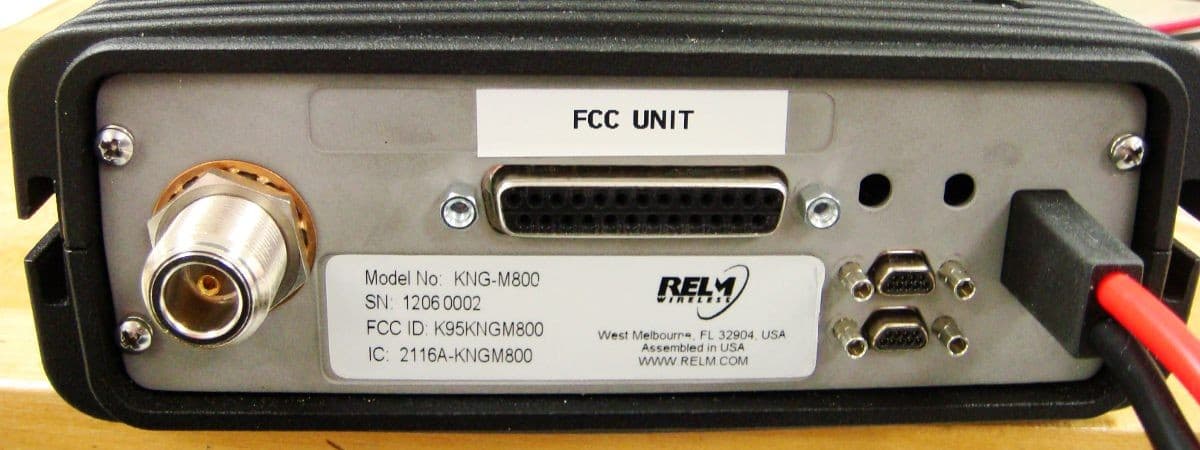
K95KNGM800
Jun 21, 2012MOBILE TRANSCEIVER
Equipment Class
TNB - Licensed Non-Broadcast Station Transmitter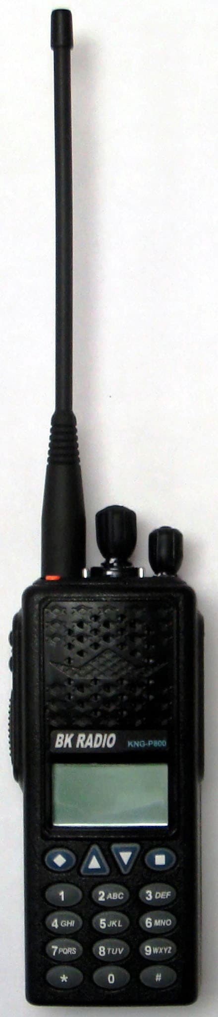
K95KNGP800C
Aug 17, 2011HANDHELD TRANSCEIVER
Equipment Class
TNF - Licensed Non-Broadcast Transmitter Held to Face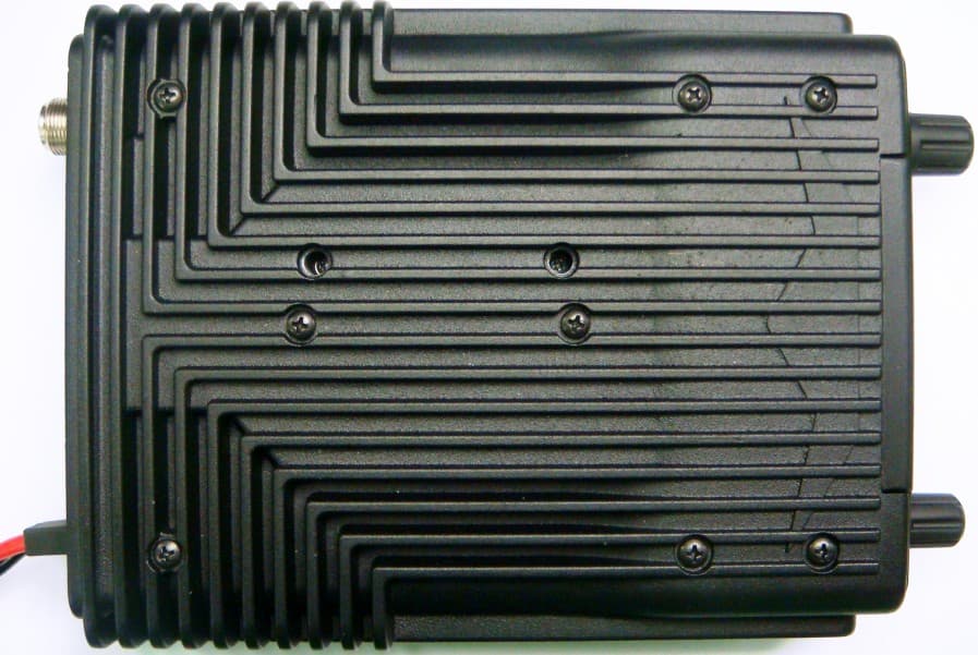
K95KNGM500
Dec 07, 2010MOBILE UHF DIGITAL RADIO
Equipment Class
TNB - Licensed Non-Broadcast Station Transmitter