KBCIX-MC8775IX-MC8775
General Dynamics Itronix Corporation
Click to zoom
Application Details
- Equipment Class
- PCB - PCS Licensed Transmitter
- Date of Grant
- May 30, 2007
- Application Purpose
- Original Equipment
- Date of Application
- May 30, 2007
- Equipment Note
- IX-MC8775
- Frequency Range
- 1852.40000000 - 1907.50000000
- Country
- United States
Documents & Files
Document Text
Text extracted from the exhibit documents filed with the FCC. Open a document above to read the original.
Users Manual
Radio Specific Safety Information Identification GoBook VR-2 (IX605) Copyright Notice © Copyright 2006. All rights reserved. No part of this document may be reproduced, transmitted, transcribed, stored in a retrieval system, or translated into any other language or computer language in whole or in part, in any form or by any means, whether it be electronic, mechanical, magnetic, optical, manual, or otherwise, without the prior written consent of General Dynamics Itronix Corporation, 12825 E. Mirabeau Parkway, Spokane Valley, WA 99216. Disclaimer General Dynamics Itronix Corporation reserves the right to revise the manual and make periodic changes to the content without a direct or inferred obligation to notify any person of such revision or changes. General Dynamics Itronix Corporation does not assume responsibility for the use of this help manual, nor for any patent infringements or other rights or third parties who may use the manual. This document contains valuable trade secrets and proprietary information of General Dynamics Itronix Corporation. This product is available for purchase under Itronix's standard terms and conditions of sale. Hardware products may be reconditioned, or be manufactured from parts and components that may be new, used, rebuilt, or recycled and in some cases, the hardware product may not be new and may have been previously installed. In any event, Itronix warranty terms apply. Warnings and Cautions WARNING It is important that only authorized personnel service and attempt repairs on the equipment. Unauthorized service or repair may void the warranty and any maintenance contract in effect for the equipment. Unauthorized service personnel might be subject to shock hazard on some equipment if removal of protective covers is attempted. Internal radio(s) may have an individual FCC Identifier which are not applicable to this configuration. Only one or more of the FCC Identifiers: KBCIX-MC5725, KBCIX-MC8775, KBCIX-4965AGN as shown on the label located on the bottom of the IX605 Laptop PC are applicable. The Radios in the IX605 Laptop PC must not be co-located or operating in conjunction with any other antenna or transmitter than specified in the above referenced FCC Certification filings . Safety Information This device may contain a WLAN radio transmitter, a Pan radio transmitter, and a WAN radio transmitter. To comply with FCC RF exposure requirements when using the WAN radio transmitter, a minimum separation distance of 20 cm must be maintained between the upper center edge of the display screen antenna and all users/bystanders. When using the WLAN transmitter, a minimum separation distance of 20 cm must be maintained between the upper right and left edges of the display screen and all users/bystanders. When using the PAN transmitter, a minimum separation distance of 20 cm must be maintained between the lower left edge of the Keyboard and all users/bystanders. The WAN transmitter, PAN transmitter and WLAN transmitter should be turned off before carrying the Laptop PC in order to comply with FCC RF exposure requirements Do not proceed beyond a WARNING or CAUTION until the indicated conditions are fully understood and met.
Users Manual
Getting Started Congratulations on your purchase of the GoBook VR-2 computer! Your new GoBook VR-2 features the most innovative advances in portable computing technology. It combines state-of-the-art ergonomics with sophisticated architecture to provide you with a personal computer that is compact, powerful, and easy to use. Designed for a wide range of general, business, and personal productivity applications, the semi-rugged, wireless ready GoBook VR-2 is an ideal choice wherever you need a computer; in the office, at home, and on the road. Your GoBook VR-2 is both expandable and portable, supporting the features you expect in a desktop computer but with the mobility of a laptop. This online document, GoBook VR-2 Help , contains all the information you need to set up and use your GoBook VR-2. For information on printing, navigating or otherwise using GoBook VR-2 Help, see the How to Use This Help System topics. If you have suggestions for how we may improve this document, please see Documentation Feedback. Unpacking Your System Inside your packaging you will find: Standard Parts Standard Features Optional Features Optional Parts and Accessories Where to Look For Information About Your Computer Page 1 of 70VR-2 Help 4/26/2007file://C:\Documents and Settings\harwoodm\Local Settings\Temp\~hh3F7F.htm About Windows The First Time. . . Before using your computer, install the battery and then attach the computer to AC power. Installing the Battery: Attaching AC Power: Begin Using the Computer 1. Open the display to a comfortable viewing angle. 2. Press the power switch to turn on the power. The POST (power-on self-test) routine executes and Windows begins loading. 1. Line up the battery connectors. 2. Press gently on the battery until it clicks into place. 3. Slide the battery locks toward the outside of the computer to lock the battery and ensure they latch completely. 1. Connect the AC adapter power cord to the AC adapter. 2. Connect the AC adapter to the DC power port on the back of your computer. 3. Connect the AC adapter power cord to a properly grounded AC outlet. NOTE It is recommended you use a quality surge protector. Page 2 of 70VR-2 Help 4/26/2007file://C:\Documents and Settings\harwoodm\Local Settings\Temp\~hh3F7F.htm NOTE When using a battery pack for the first time, it is recommended that you calibrate the battery so the gas gauge accurately displays battery capacity. Turning off Your Computer Turning off the computer properly is important to maintaining your computer. Select Start , Shut Down and follow the instructions on the screen. If you are going to be away from the computer for a short period, there are ways to conserve power without shutting down the system. See Managing Power and Battery Tips for details. NOTE If you are unable to shut down your computer normally, follow the instructions in Troubleshooting . NOTE If you are using an office or vehicle dock, please refer to Undocking the VR -2 in the Optional Equipment and Accessories section. CAUTION Shutting off the computer improperly may result in data loss. Startup Problems? If your computer does not startup properly, try these solutions. z Connect the AC adapter to charge the battery if it is not charged. NOTE If the AC adapter is connected and functioning properly, the Power LED on the AC adapter should be lit as well as the External Power LED on the GoBook VR-2. z If the AC adapter is connected but the unit will still not turn on, make sure the electrical outlet you are using works. z Check to make sure the battery is installed and charged properly. z If the battery does not begin charging, remove the battery, connect the AC adapter, and turn on the computer by pressing the Power Button . Reinstall the battery. The Battery LED is a steady green while the battery is charging. The Troubleshooting section lists additional solutions you can try. Safety Read these instructions carefully and save them. Following these guidelines will help prevent damage to your computer and help protect your personal safety. z Follow all warnings and instructions marked on the product and noted in this documentation, including the Notices and Compliance section z Follow all warnings and instructions noted in Windows Help and Support , found on the Start Menu z The first time you use your computer, we recommend that you carefully read the section on Power Management to familiarize yourself with basic battery information and ensure optimum performance z WARNING! There is danger of explosion if the battery is incorrectly replaced. Replace only with the same or equivalent type recommended by the manufacturer. Dispose of used batteries according to the manufacturer's instructions Page 3 of 70VR-2 Help 4/26/2007file://C:\Documents and Settings\harwoodm\Local Settings\Temp\~hh3F7F.htm z WARNING! Batteries may explode if not handled properly. Do not disassemble or dispose of them in fire. Keep them away from children and dispose of used batteries promptly z Unplug the computer from the power outlet before cleaning. Use a damp cloth for cleaning. Do not use aerosols, solvents, or strong detergents z CAUTION The computer may be damaged if exposed to contaminants. Shield the unit from all contaminants such as liquids, rain, snow, and dust z Slots and openings in the computer case are for ventilation purposes. Do not block or cover these openings or the system could overheat z Do not place the product on a soft surface such as a bed, sofa, or rug where the ventilation slots and openings may be blocked z Do not place this product near or over a radiator or heat register z Do not place this product in a built-in installation unless proper ventilation is provided z Do not operate the computer at temperatures above 140°F (60°C) or below -4°F (-20C) z Do not store the computer at temperatures above 140°F (60°C) or below -67°F (-55°C) z Do not step on or place anything on the power cord z If you use the computer with an extension cord, ensure that the to…
Text truncated - open the document above for the full version.
Cover Letter(s)
Northwest EMC TCB Compliance Opinion Rev. 9/15/03 SPTE0050 Information about the Applicant Company Name General Dynamics Itronix Corporation Grantee Mark Harwood Address 12825 E.Mirabeau Parkway City, State, Zip Spokane Valley, WA 99216 Job Number SPTE0050 Model IX-MC8775 FCC ID KBCIX-MC8775 Agent Rod Munro Approval Type Original Equipment Class PCB PCS Licensed Transmitter Rule Part 22H, 24E Overview This application is for a limited modular approval for the Sierra Wireless, PCI Express Mini-card, Model MC8775 to be installed only in the Itronix IX605 Rugged Laptop computer under FCC rule parts 22H and 24E. Recommendation All items have been resolved and completed to my satisfaction; therefore I recommend this application for approval. Signature Dave Tolman, TCB Committee 5/16/2007
Cover Letter(s)
August 2, 2006 Federal Communications Commission Authorization and Standards Division 7435 Oakland Mills Road Columbia, M.D. 21046 To Whom It May Concern: Re: Confidentiality Request for FCC ID N7NMC8775 We hereby request that the documentation listed below, submitted with our application for certification, be withheld from public disclosure. This request is made under the provisions of Section 0.457(d) of the Commission’s Rules, and Section 552(b)(4) of the Freedom of Information Act. We cite trade secrets as the reason and purpose of the request. 1. MC8775 Schematics 2. MC8775 Block Diagram 3. MC8775 Detailed Circuit Description 4. MC8775 Tune Up Procedure Sincerely, Ying Wang Senior RF Engineer
Cover Letter(s)
209 Dayton Street, Suite 205 Edmonds, WA 98020-3581 425 771-4482 425 486-1933 Fax May 17, 2007 Northwest EMC, Inc. 22975 NW Evergreen Parkway, #400 Hillsboro, OR 97124 % Vicki Albertson Re: Applicant: General Dynamics Itronix Corporation FCC ID: KBCIX-MC8765 1.) Limited Modular Certification for the Sierra Wireless, Inc. Model: MC8775, PCI Express Mini- Card Model: MC8775, 3-G enabled EDGE, GPRS, and GSM, dual band UMTS, HSDPA, Release 5, embedded in Itronix Model: IX605 Rugged Laptop PC and use with optional IX605 Vehicle Mount. 2.) Co-location with the FCC ID: KBCIX-4965AGN, an 802.11 A,B,G,N, WLAN. TCB Committee, The IX605 Rugged Host PC is a platform designed for use with several different radio types. These may include one or more of the following radio types: Bluetooth, WLAN and WAN (either CDMA or GSM). Certification applications are pending for, but not limited to all combinations of the following devices listed by FCC ID(s): KBCIX-4965AGN (WLAN), KBCIX-BT-52 (Bluetooth), KBCIX-MC5725 (WAN), and KBCIX-MC8775 (WAN). Only one radio of each type, Bluetooth, WLAN or WAN, can be installed and used at a time. Co-located MPE calculations and other exhibits for each possible combination are included in the applicable Certification filings. The scope of this specific application is detailed in the following three paragraphs. On behalf of General Dynamics Itronix Corporation we request a Limited Modular Certification for the Sierra Wireless, PCI Express Mini-Card, Model: MC8775; embedded in the IX605 Rugged PC under Parts 22H & 24E. We also request that this Certification include Co-location with the above referenced Limited Modular Certified Intentional radiator. Exhibits supporting this request are submitted with this application. We would like to reference the OEM, Sierra Wireless, Inc. Modular Certification test report prepared by CCS for all of the conducted test data. The radiated spurious and ERP/EIRP measurements made by NW EMC, Inc. would cover the integration of the MC8775 embedded module into the IX605 host with two new antenna combinations. The IX605 Vehicle Mount option extends many of the PC I/O ports and the switches the RF output of the WAN radio to an external antenna. Placing the IX605 in the cradle automatically causes the cradle contact board to switch the output of the MC8775 transmitter from the internal antenna located in the PC display, to and through the IX605 Vehicle Mount to an SMA connector and then to the external antenna. The external vehicular antenna sold by Itronix with this package is a 3 dBi gain antenna manufactured by MaxRad Model: BMLPVDB800/1900 along with the Model: LMR195 vehicle antenna ¾” magnetic mount with 17 ft of coax. Best Regards, Rod Munro Agent, Itronix Corp. President, Spectrum Technology, Inc. [email protected]
Cover Letter(s)
Applicant: ITRONIX, Corporation FCC ID: KBCIX-MC8775 EUT Info. a) The IX605 rugged laptop and IX605 Vehicle Mount used were pre- production. The MC8775 embedded radio module was a production model. b) No modifications to the equipment were made during testing. c) Manufacturer: Sierra Wireless, Inc. Model: MC8775 Revision: H1_0_0_7MCAP G:/WS/FW/H1_0_0_7MCAP/MSM6280/SRC 2006/10/26 17:31:03 : 352678010100326 IMEI SV: 3 FSN: X283656095510 3GPP Release 5 +GCAP: +CGSM,+DS,+ES The transmitter was enabled with: Sierra Wireless Watcher Program. The radio function confirmation and call answering was done with ProComm Plus Terminal program. 2.) ERP, EIRP and Emissions testing was done with a “over the air” (OTA) connection to a Rohde & Schwarz, CMU200 Communications Test Set with the required software licensing to allow; GSM, GPRS, EGPRS, W-CDMA, & HSDPA, over the air (OTA) connectivity. d) Emissions Designators FCC Rule Parts Frequency Range (MHZ) Output Watts Frequency Tolerance Emission Designator 24E 1850.2 - 1909.8 0.817 0.1 PM 244KGXW 24E 1850.2 - 1909.8 0.399 0.1 PM 243KG7W 24E 1852.4 - 1907.6 0.202 0.1 PM 4M15F9W 22H 824.2 - 848.8 1.611 0.1 PM 244KGXW 22H 824.2 - 848.8 0.491 0.1 PM 246KG7W 22H 826.4 - 846.6 0.208 0.1 PM 4M15F9W e) Necessary Bandwidth Justification. The summary of the Occupied Bandwidth test results are located on page 7 of the OEM test report and the supporting plots on the pages following. A copy of this test report is submitted along with this application. Reference also the Sierra Wireless OEM modular grant for 1 Applicant: ITRONIX, Corporation FCC ID: KBCIX-MC8775 FCC ID: N7NMC8765 for which the conducted emissions test data is submitted. f) For the dc voltages applied to and dc currents into several elements. Please refer to the information that has been provided in the confidential OEM Operational Description submitted to NW EMC directly from Sierra Wireless, Inc. 2
External Photos
Applicant: General Dynamics Itronix, Corporation FCC ID: KBCIX-MC8775 External Photos IX605 Host and KBCIX-MC8775 WAN Top View Closed Bottom View 1 Applicant: General Dynamics Itronix, Corporation FCC ID: KBCIX-MC8775 IX605 Front View Open 2 Applicant: General Dynamics Itronix, Corporation FCC ID: KBCIX-MC8775 IX605 Back Side Open IX605 I/O Ports 3 Applicant: General Dynamics Itronix, Corporation FCC ID: KBCIX-MC8775 IX605 Right Side IX605 Left Side 4 Applicant: General Dynamics Itronix, Corporation FCC ID: KBCIX-MC8775 External Photos KBCIX-MC8775 CRMA Embedded Module Slot for CRMA module with out the IX-MC8775 Slot for CRMA module with the IX-MC8775 CRMA module with IX-MC5725 partially removed 5 Applicant: General Dynamics Itronix, Corporation FCC ID: KBCIX-MC8775 IX-MC8775 CRMA module top view IX-MC8775 CRMA module bottom view 6
ID Label/Location Info
Grantee: General Dynamics Itronix Corporation FCC ID: KBCIX-MC8775 FCC ID Label Facsimile for the FCC ID: KBCIX-MC875 And Label Location on the IX605 FCC ID Label Facsimile shown below: The FCC ID label location on the IX605 is shown on the next page.
Internal Photos
Applicant: General Dynamics Itronix, Corporation FCC ID: KBCIX-MC8775 Internal Photos IX605 Host and the KBCIX-MC8775 Top view, PC closed; back display cover removed WAN, WLAN & GPS antennas visible X605 WAN SkyCross antenna with blue PCB center above. Co-Located WLAN Main and Aux antenna located upper right and left hand sides of display. GPS module and antenna, to the left of the WAN SkyCross antenna above. 1 Applicant: General Dynamics Itronix, Corporation FCC ID: KBCIX-MC8775 SkyCross Antenna Co-Located WLAN, Inverted F antenna left and right 2 Applicant: General Dynamics Itronix, Corporation FCC ID: KBCIX-MC8775 Internal Photos of KBCIX-MC8775 CRMA, covers removed. Top View of the IX-MC8775 CRMA Bottom View of the IX-MC875 CRMA 3 Applicant: General Dynamics Itronix, Corporation FCC ID: KBCIX-MC8775 Top and Bottom View of the IX-MC875 with OEM Label & Shielding 4 Applicant: General Dynamics Itronix, Corporation FCC ID: KBCIX-MC8775 Top and Bottom View of the IX-MC875 Shielding Removed 5
Operational Description
Applicant: General Dynamics Itronix Corporation FCC ID: KBCIX-MC8775 Antenna Information Internal and External WAN Antenna Information FCC ID: KBCIX-MC8775 Antenna Model Antenna Part No. Frequency (MHz) Antenna Type Antenna Gain (dBi) IX605 PRIMARY WAN ANTENNA Skycross 2-2920 825-894 MHz Meander Line 3.4 IX605 PRIMARY WAN ANTENNA Skycross 2-2920 880-960 MHz Meander Line 2.5 IX605 PRIMARY WAN ANTENNA Skycross 2-2920 1710-1880 MHzMeander Line 0.3 IX605 PRIMARY WAN ANTENNA Skycross 2-2920 1850-1990 MHzMeander Line 1.8 External – MaxRad 3 dBi Gain BMLPVDB800/1900806 - 960 Low profile vertical3 External – MaxRad 3 dBi Gain BMLPVDB800/19001710-1990 Low profile vertical3 Note; The Antenna Gain listed for the Meander Line Antenna includes cabling from the DEAC to the antenna.
RF Exposure Info
Applicant: General Dynamics Itronix Corporation FCC ID: KBCIX-MC8775 1 Compliance with 47 CFR 15.247(i) “Systems operating under the provisions of this section shall be operated in a manner that ensures that the public is not exposed to radio frequency energy levels in excess of the Commission's guidelines. See § 1.1307(b)(1) of this chapter.” The EUT will only be used with a separation distance of 20 centimeters or greater between the antenna and the body of the user or nearby persons and can therefore be considered a mobile transmitter per 47 CFR 2.1091 (b). Calculations are provided for each radio transmitting through its own internal antenna and optional external antenna. The total transmit power is less than 1.5 W (ERP), therefore the EUT is categorically excluded from routine environmental evaluation per 47 CFR 2.1091(c). The MPE estimates are as follows: Table 1 in 47 CFR 1.1310 defines the maximum permissible exposure (MPE) for the general population. The exposure level at a 20 cm distance from the EUT’s transmitting antenna is calculated using the general equation: S = (PG)/4πR 2 Where: S = power density (mW/cm 2 ) P = power input to the antenna (mW) G = numeric power gain relative to an isotropic radiator R = distance to the center of the radiation of the antenna (20 cm = limit for MPE estimates) PG = EIRP Solving for S, the maximum power densities 20 cm from the transmitting antennas are summarized in the tables on the following pages: Applicant: General Dynamics Itronix Corporation FCC ID: KBCIX-MC8775 2 MPE Estimates for Self Located Device FCC ID: KBCIX-MC8775 In the IX605 Host PC GSM, GPRS, EDGE, UMTS, WCDMA, HSDPA Antenna Type Antenna Part No. Transmit Frequency Max Peak EIRP Output Max ERP Output Power Density @ 20 cm Source- based time averaging corrected Power Density @ 20 cm General Population Exposure Limit from 1.1310 Ratio of Power Density to the Exposure Limit IX605 Primary WAN (MHz) (mW) (mW) (mW/cm 2 ) (mW/cm 2 ) (mW/cm 2 ) Meander Line Skycross 2-2920 848.8 3872.04 2361 0.770 0.1925 0.56 0.340 Meander Line Skycross 2-2920 1850.2 1589.0 0.316 0.079 1 0.079 Worst Case Ratio of Power Density to the Exposure Limit = 0.340 Source-based time averaging corrected for the GPRS Duty Cycle of 25% “worst case”. Excerpts from TCB Training, April 3, 2002, “Mobile Transmitters”, Slide 6: “Devices operating in multiple frequency bands When RF exposure evaluation is required for TCB approval o Separate antennas – estimated minimum separation distances may be considered for the frequency bands that do not require evaluation or TCB approval, however, the estimated distance should take into account the effect of co-located transmitters. (Note 24) Note 24 According to multiple frequency exposure criteria, the ratio of field strength or power density to the applicable exposure limit at the exposure location should be determined for each transmitter and the sum of these ratios must not exceed 1.0 for the location to be compliant .” The sum of the ratio(s) (power density to the exposure limit) does not exceed 1.0; therefore, the exposure condition is compliant with FCC rules. Applicant: General Dynamics Itronix Corporation FCC ID: KBCIX-MC8775 3 MPE Estimates for Self Located Device FCC ID: KBCIX-4965AGN WLAN, IEEE 802.11 (a) (b) (g) & (n) Antenna Type Antenna Part No. Transmit Frequency Max Peak Conducted Output Power Antenna Gain Minimum Antenna Cable Loss Power Density @ 20 cm General Population Exposure Limit from 1.1310 Ratio of Power Density to the Exposure Limit (MHz) (mW) (dBi) (dB) (mW/cm 2 ) (mW/cm 2 ) Part 15C Inverted F MAIN EST07-10 5745-5825 303 -2.0 2.0 0.024 1 0.024 Inverted F MAIN EST07-10 2412-2462 463 -3.5 0.9 0.033 1 0.033 External MaxRad MAXC24503 2412-2462 463 3 4.4 0.067 1 0.067 External MaxRad BMAXC24505 2412-2462 463 5 4.4 0.106 1 0.106 Part 15 E Inverted F MAIN EST07-10 5180-5240 50 -2.0 2.0 0.004 1 0.004 Inverted F MAIN EST07-10 5260-5320 123 -2.0 2.0 0.010 1 0.010 Worst Case Ratio of Power Density to the Exposure Limit = 0.106 Worst Case Co-located Exposure Condition FCC ID: KBCIX-MC8775 FCC ID: KBCIX-4965AGN Per Note 24 shown below, the Sum of Worst Case Power Ratios cannot exceed 1.0 * Note: GPRS 25% Duty Cycle “worst case” was taken in to account for GSM radio. GSM Radio Worst Case Ratio of Power Density to the Exposure Limit 802.11abgn Radio Worst Case Ratio of Power Density to the Exposure Limit Sum of Worst Case Ratios (Power Density to the Exposure Limit) FCC Limit for Sum of Worst Case Ratios 0.340 0.106 0.446 1.0 * PASS The results shown in the above table are equivalent to the Sum of the EIRP of the Two Co-located Transmitters (EIRP TX1 + EIRP TX2) compared to the exposure limit. The benefit of this method, is that accounts for transmitters operating at different frequencies against different exposure limits.
RF Exposure Info
Applicant: General Dynamics Itronix Corporation FCC ID: KBCIX-MC8775 1 Compliance with 47 CFR 15.247(i) “Systems operating under the provisions of this section shall be operated in a manner that ensures that the public is not exposed to radio frequency energy levels in excess of the Commission's guidelines. See § 1.1307(b)(1) of this chapter.” The EUT will only be used with a separation distance of 20 centimeters or greater between the antenna and the body of the user or nearby persons and can therefore be considered a mobile transmitter per 47 CFR 2.1091 (b). Calculations are provided for each radio transmitting through its own internal antenna and optional external antenna. The total transmit power is less than 1.5 W (ERP), therefore the EUT is categorically excluded from routine environmental evaluation per 47 CFR 2.1091(c). The MPE estimates are as follows: Table 1 in 47 CFR 1.1310 defines the maximum permissible exposure (MPE) for the general population. The exposure level at a 20 cm distance from the EUT’s transmitting antenna is calculated using the general equation: S = (PG)/4πR 2 Where: S = power density (mW/cm 2 ) P = power input to the antenna (mW) G = numeric power gain relative to an isotropic radiator R = distance to the center of the radiation of the antenna (20 cm = limit for MPE estimates) PG = EIRP Solving for S, the maximum power densities 20 cm from the transmitting antennas are summarized in the tables on the following pages: Applicant: General Dynamics Itronix Corporation FCC ID: KBCIX-MC8775 2 MPE Estimates for Self Located Device FCC ID: KBCIX-MC8775 In the IX605 Host PC GSM, GPRS, EDGE, UMTS, WCDMA, HSDPA Antenna Type Antenna Part No. Transmit Frequency Max Peak EIRP Output Max ERP Output Power Density @ 20 cm Source- based time averaging corrected Power Density @ 20 cm General Population Exposure Limit from 1.1310 Ratio of Power Density to the Exposure Limit IX605 Primary WAN (MHz) (mW) (mW) (mW/cm 2 ) (mW/cm 2 ) (mW/cm 2 ) Meander Line Skycross 2-2920 848.8 3872.04 2361 0.770 0.1925 0.56 0.340 Meander Line Skycross 2-2920 1850.2 1589.0 0.316 0.079 1 0.079 Worst Case Ratio of Power Density to the Exposure Limit = 0.340 Source-based time averaging corrected for the GPRS Duty Cycle of 25% “worst case”. Excerpts from TCB Training, April 3, 2002, “Mobile Transmitters”, Slide 6: “Devices operating in multiple frequency bands When RF exposure evaluation is required for TCB approval o Separate antennas – estimated minimum separation distances may be considered for the frequency bands that do not require evaluation or TCB approval, however, the estimated distance should take into account the effect of co-located transmitters. (Note 24) Note 24 According to multiple frequency exposure criteria, the ratio of field strength or power density to the applicable exposure limit at the exposure location should be determined for each transmitter and the sum of these ratios must not exceed 1.0 for the location to be compliant .” The sum of the ratio(s) (power density to the exposure limit) does not exceed 1.0; therefore, the exposure condition is compliant with FCC rules.
Test Report
Spectrum Technology, Inc. MC8775 in the IX605 May 08, 2007 Report No. SPTE0050 Report Prepared By www.nwemc.com 1-888-EMI-CERT © 2007 Northwest EMC, Inc 22975 NW Evergreen Parkway Suite 400 Hillsboro, Oregon 97124 Certificate of Test Issue Date: May 08, 2007 Spectrum Technology Model: MC8775 in the IX605 Emissions Test Description Specification Test Method Pass Fail Effective Isotropic Radiated Power FCC 24E:2006 ANSI/TIA/EIA-603-B:2002 Effective Radiated Power FCC 22H:2006 ANSI/TIA/EIA-603-B:2002 Out of Band Emissions FCC 24E:2006 ANSI/TIA/EIA-603-B:2002 Out of Band Emissions FCC 22H:2006 ANSI/TIA/EIA-603-B:2002 Modifications made to the product See the Modifications section of this report Test Facility The measurement facility used to collect the data is located at: Northwest EMC, Inc. 22975 NW Evergreen Parkway, Suite 400 Hillsboro, OR 97124 Phone: (503) 844-4066 Fax: 844-3826 This site has been fully described in a report filed with and accepted by the FCC (Federal Communications Commission) and Industry Canada. Approved By: Ethan Schoonover, Sultan Lab Manager This report must not be used to claim product certification, approval, or endorsement by NVLAP, NIST, or any agency of the federal government of the United States of America. Product compliance is the responsibility of the client, therefore the tests and equipment modes of operation represented in this report were agreed upon by the client, prior to testing. This Report may only be duplicated in its entirety. The results of this test pertain only to the sample(s) tested, the specific description is noted in each of the individual sections of the test report supporting this certificate of test. Northwest EMC Revision History Revision 05/05/03 Revision Number Description Date Page Number 00 None Northwest EMC Accreditations and Authorizations Revision 03/18/05 FCC: Accredited by NVLAP for performance of FCC radio, digital, and ISM device testing. Our Open Area Test Sites, certification chambers, and conducted measurement facilities have been fully described in reports filed with the FCC and accepted by the FCC in letters maintained in our files. Northwest EMC has been accredited by ANSI to ISO / IEC Guide 65 as a product certifier. We have been designated by the FCC as a Telecommunications Certification Body (TCB). This allows Northwest EMC to certify transmitters to FCC specifications in accordance with 47 CFR 2.960 and 2.962. NVLAP: Northwest EMC, Inc. is accredited under the United States Department of Commerce, National Institute of Standards and Technology, and National Voluntary Laboratory Accreditation Program for satisfactory compliance with the requirements of ISO/IEC 17025 for Testing Laboratories. The NVLAP accreditation encompasses Electromagnetic Compatibility Testing in accordance with the European Union EMC Directive 89/336/EEC, ANSI C63.4, MIL- STD 461E, DO-160D and SAE J1113. Additionally, Northwest EMC is accredited by NVLAP to perform radio testing in accordance with the European Union R&TTE Directive 1999/5/EEC, the requirements of FCC, and the RSS radio standards for Industry Canada. NVLAP LAB CODE 200629-0 NVLAP LAB CODE 200630-0 NVLAP LAB CODE 200676-0 NVLAP LAB CODE 200761-0 Industry Canada: Accredited by NVLAP for performance of Industry Canada RSS and ICES testing. Our Open Area Test Sites and certification chambers comply with RSS 212, Issue 1 (Provisional) and have been filed with Industry Canada and accepted. Northwest EMC has been accredited by ANSI to ISO / IEC Guide 65 as a product certifier. We have been designated by NIST and recognized by Industry Canada as a Certification Body (CB) per the APEC Mutual Recognition Arrangement (MRA). This allows North…
Text truncated - open the document above for the full version.
Contact Information
Applicant
Ray Garcia(Agency Manager)
Test Firm
Northwest EMC, Inc.Greg Kiemel
Technical Specifications
| # | Rule Parts | Frequency Range | Power Output | Emission | Tolerance |
|---|---|---|---|---|---|
| 6 | 24E | 1.85 GHz - 1.91 GHz | 826.00 mW | 4M15F9W | 0.1 ppm |
Other Applications from General Dynamics Itronix Corporation

KBCIX-BR-51
Jan 20, 2008IX-BTBR51
Equipment Class
DSS - Part 15 Spread Spectrum Transmitter
KBCIX-4965AGN
May 21, 2007IX-4965AGN
Equipment Class
NII - Unlicensed National Information Infrastructure TX
KBCIX-AC595
Apr 19, 2007IX-AC595 DUAL-BAND CDMA/EV-DO PCMCIA MODEM CARD
Equipment Class
PCB - PCS Licensed Transmitter
KBCIX-NW620
Mar 13, 2007IX-NW620 CDMA/EV-DO
Equipment Class
PCB - PCS Licensed Transmitter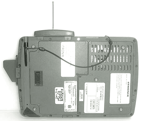
KBCIX325A860IWLBT
Nov 13, 2006TABLET PC w/ WLAN, BLUETOOTH & GSM/GPRS/EDGE/UMTS
Equipment Class
DTS - Digital Transmission System