KBS050232Pet Containment System M023200
Radio Systems Corporation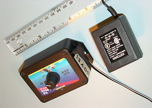
Click to zoom
Application Details
- Equipment Class
- DCD - Part 15 Low Power Transmitter Below 1705 kHz
- Date of Grant
- Oct 17, 2000
- Application Purpose
- Original Equipment
- Date of Application
- Oct 17, 2000
- Equipment Note
- Pet Containment System M023200
- Frequency Range
- 0.00900000 - 0.01400000
- Company
- Radio Systems Corporation
- Country
- United States
Documents & Files

Document Text
Text extracted from the exhibit documents filed with the FCC. Open a document above to read the original.
Users Manual
TRAINING INFORMATION Innotek is proud to be the exclusive electronic training products sponsor of Triple Crown All Breed Dog Academy of greater Austin, TX. For more information on Triple Crown, visit their web site at www.triplecrowndogs.com LIMITED WARRANTY Innotek warrants that this product will be free from defects in material and workmanship under normal use for one year from the date of original consumer purchase. Within 30 days of the original consumer purchase, this product is covered by Innotek’s 30-day money- back guarantee. If you are not satisfied with the performance of this product, you may return it with the original receipt to the place of purchase for a full refund. After 30 days and during the one-year limited warranty period we will, at our option, repair or replace defective part(s) for a $15 processing fee. Shipping costs to our facility are not covered by this limited warranty. This limited warranty is offered only to the original consumer purchaser. This limited warranty is subject to the condition that any covered defect occurs under normal conditions of use and maintenance and that Innotek receives prompt written notice of the discovery of the defect within the limited warranty period. It does not apply to damage or failures that result from physical abuse or misuse of the product. The limited warranty is void if any attempts are made to alter or repair this product prior to returning it to our facility within the limited warranty period. This limited warranty does not cover lost parts or broken probe studs. EXCEPT AS SPECIFICALLY SET FORTH HEREIN, THERE ARE NO WARRANTIES, REPRESENTATIONS, PROMISES OR ASSURANCES BY INNOTEK, EITHER EXPRESSED OR IMPLIED, WHETHER BY LAW, CUSTOM, PREVIOUS TRANSACTION OR OTHERWISE, INCLUDING WITHOUT LIMITATION, WARRANTIES OF MERCHANTABILITY OR FITNESS FOR A PARTICULAR PURPOSE WITH REGARD TO THE PRODUCT. INNOTEK’S LIABILITY IS SOLELY AS STATED HEREIN AND NO OTHER LIABILITY SHALL EXIST, WHETHER BY NEGLIGENCE, STRICT LIABILITY, TORT OR ANY OTHER CAUSE OR ACTION. ALL LIABILITIES FOR INNOTEK STATED HEREIN ARE THE SOLE AND EXCLUSIVE REMEDIES OF THE ORIGINAL CONSUMER PURCHASER. IN NO EVENT SHALL INNOTEK BE LIABLE FOR ANY CONSEQUENTIAL OR INCIDENTAL DAMAGES, OR ANY OTHER TYPE OF DAMAGE WHICH MAY BE CAUSED IN WHOLE OR IN PART BY ANY FAILURE, DEFECT OR PROBLEM OF THE PRODUCT. This product is not a substitute for traditional obedience training in situations where attractive nuisance or canine personality would reasonably require such training. Some states do not allow the exclusion or limitation of incidental or consequential damages, so the above limitation or exclusion may not apply to you. If services are required, contact the Innotek Call Center to get your Return Materials Authorization Number (RMA) and return instructions. Send the defective part or the complete system by insured U.S. Mail or UPS to the address below: Include a check or money order for $15 to cover processing and handling. FCC NOTICE This device has been tested and found to comply with the limits for a Class B digital device, pursuant to Part 15 of the FCC Rules. These limits are designed to provide reasonable protection against harmful interference in a residential installation. This device generates, uses, and can radiate radio frequency energy and, if installed and used in accordance with the instruction, may cause harmful interference to radio communications. However, there is no guarantee that interference will not occur in a particular installation. If this device does cause harmful interference to radio or television reception, the user is encouraged to try to correct the interference by one or more of the following measures: • Reorient or relocate the receiving antenna. • Increase the separation between the computer and receiver. • Connect the computer into an outlet on a circuit different from that to which the receiver is connected. • Consult the dealer or an experienced radio/TV technician for help. Caution: Any changes or modifications not expressly approved by the grantee of this device could void the user’s authority to operate the equipment. Rev. 03/00 P/N: 2100151 IMPORTANT! DO NOT BURY THE WIRE UNTIL YOU HAVE TESTED THE SYSTEM AND ARE SURE IT IS WORKING PROPERLY! Use gradual turns at the corners. This will produce a more consistent signal field and avoid confusing the dog in these areas. IMPORTANT! Do not run the loop within six feet parallel to electrical, telephone, cable TV or any other buried wire you may have in your yard. Do not run one section of wire within 10 feet of an other section or the signal may cancel. Do not run your wire within 10 feet of a neighboring containment system’s boundary wire. Driveways/Sidewalks - When crossing an asphalt driveway, make a 1/2" deep cut across the driveway using a circular saw and masonry blade. Place the wire in the crack and seal with asphalt sealant. On driveways and sidewalks, if an expansion joint is available, simply place the wire in the joint and seal with an outdoor caulk. When crossing gravel, bury the wire at least 3" deep. Use an old garden hose or plastic PVC piping to protect the wire. In water, anchor the wire with large rocks. Protect the wire with an old garden hose or plastic PVC piping. Connecting the Loop to the Transmitter 1. Splice the two ends of the twisted wire to each of the two ends of the loop wire. 2. Drill a hole through the exterior wall or window/ door sill, or run the wire through an existing utility line hole. 3. Connect the twisted wires to the transmitter, either wire to either terminal. (Wire ends must be stripped.) 4. A red indicator light should appear, indicating a continuous wire loop. If no light appears, refer to Section 1, Part C. SECTION 6: THE SIGNAL FIELD The width of the signal field is adjusted using the transmitter’s Field Width Adjustment Knob. Increasing or decreasing the signal field width does not affect the correction intensity. To test the signal field, hoo…
Text truncated - open the document above for the full version.
Users Manual
TRAINING INFORMATION Innotek is proud to be the exclusive electronic training products sponsor of Triple Crown All Breed Dog Academy of greater Austin, TX. For more information on Triple Crown, visit their web site at www.triplecrowndogs.com LIMITED WARRANTY Innotek warrants that this product will be free from defects in material and workmanship under normal use for one year from the date of original consumer purchase. Within 30 days of the original consumer purchase, this product is covered by Innotek’s 30-day money- back guarantee. If you are not satisfied with the performance of this product, you may return it with the original receipt to the place of purchase for a full refund. After 30 days and during the one-year limited warranty period we will, at our option, repair or replace defective part(s) for a $15 processing fee. Shipping costs to our facility are not covered by this limited warranty. This limited warranty is offered only to the original consumer purchaser. This limited warranty is subject to the condition that any covered defect occurs under normal conditions of use and maintenance and that Innotek receives prompt written notice of the discovery of the defect within the limited warranty period. It does not apply to damage or failures that result from physical abuse or misuse of the product. The limited warranty is void if any attempts are made to alter or repair this product prior to returning it to our facility within the limited warranty period. This limited warranty does not cover lost parts or broken probe studs. EXCEPT AS SPECIFICALLY SET FORTH HEREIN, THERE ARE NO WARRANTIES, REPRESENTATIONS, PROMISES OR ASSURANCES BY INNOTEK, EITHER EXPRESSED OR IMPLIED, WHETHER BY LAW, CUSTOM, PREVIOUS TRANSACTION OR OTHERWISE, INCLUDING WITHOUT LIMITATION, WARRANTIES OF MERCHANTABILITY OR FITNESS FOR A PARTICULAR PURPOSE WITH REGARD TO THE PRODUCT. INNOTEK’S LIABILITY IS SOLELY AS STATED HEREIN AND NO OTHER LIABILITY SHALL EXIST, WHETHER BY NEGLIGENCE, STRICT LIABILITY, TORT OR ANY OTHER CAUSE OR ACTION. ALL LIABILITIES FOR INNOTEK STATED HEREIN ARE THE SOLE AND EXCLUSIVE REMEDIES OF THE ORIGINAL CONSUMER PURCHASER. IN NO EVENT SHALL INNOTEK BE LIABLE FOR ANY CONSEQUENTIAL OR INCIDENTAL DAMAGES, OR ANY OTHER TYPE OF DAMAGE WHICH MAY BE CAUSED IN WHOLE OR IN PART BY ANY FAILURE, DEFECT OR PROBLEM OF THE PRODUCT. This product is not a substitute for traditional obedience training in situations where attractive nuisance or canine personality would reasonably require such training. Some states do not allow the exclusion or limitation of incidental or consequential damages, so the above limitation or exclusion may not apply to you. If services are required, contact the Innotek Call Center to get your Return Materials Authorization Number (RMA) and return instructions. Send the defective part or the complete system by insured U.S. Mail or UPS to the address below: Include a check or money order for $15 to cover processing and handling. FCC NOTICE This device has been tested and found to comply with the limits for a Class B digital device, pursuant to Part 15 of the FCC Rules. These limits are designed to provide reasonable protection against harmful interference in a residential installation. This device generates, uses, and can radiate radio frequency energy and, if not installed and used in accordance with the instruction, may cause harmful interference to radio communications. However, there is no guarantee that interference will not occur in a particular installation. If this device does cause harmful interference to radio or television reception, the user is encouraged to try to correct the interference by one or more of the following measures: • Reorient or relocate the receiving antenna. • Increase the separation between the computer and receiver. • Connect the computer into an outlet on a circuit different from that to which the receiver is connected. • Consult the dealer or an experienced radio/TV technician for help. Caution: Any changes or modifications not expressly approved by the grantee of this device could void the user’s authority to operate the equipment. Rev. 03/00 P/N: 2100151 IMPORTANT! DO NOT BURY THE WIRE UNTIL YOU HAVE TESTED THE SYSTEM AND ARE SURE IT IS WORKING PROPERLY! Use gradual turns at the corners. This will produce a more consistent signal field and avoid confusing the dog in these areas. IMPORTANT! Do not run the loop within six feet parallel to electrical, telephone, cable TV or any other buried wire you may have in your yard. Do not run one section of wire within 10 feet of an other section or the signal may cancel. Do not run your wire within 10 feet of a neighboring containment system’s boundary wire. Driveways/Sidewalks - When crossing an asphalt driveway, make a 1/2" deep cut across the driveway using a circular saw and masonry blade. Place the wire in the crack and seal with asphalt sealant. On driveways and sidewalks, if an expansion joint is available, simply place the wire in the joint and seal with an outdoor caulk. When crossing gravel, bury the wire at least 3" deep. Use an old garden hose or plastic PVC piping to protect the wire. In water, anchor the wire with large rocks. Protect the wire with an old garden hose or plastic PVC piping. Connecting the Loop to the Transmitter 1. Splice the two ends of the twisted wire to each of the two ends of the loop wire. 2. Drill a hole through the exterior wall or window/ door sill, or run the wire through an existing utility line hole. 3. Connect the twisted wires to the transmitter, either wire to either terminal. (Wire ends must be stripped.) 4. A red indicator light should appear, indicating a continuous wire loop. If no light appears, refer to Section 1, Part C. SECTION 6: THE SIGNAL FIELD The width of the signal field is adjusted using the transmitter’s Field Width Adjustment Knob. Increasing or decreasing the signal field width does not affect the correction intensity. To test the signal field,…
Text truncated - open the document above for the full version.
Users Manual
Innotek’s Pet Containment System provides security for your dog and peace of mind for you. Its humane stimulation is proven safe and effective for training dogs to stay within the boundaries you set. This system, Model CB-100W, features Innotek’s micro-size collar receiver - our smallest ever - along with bark-control functions. This unique, dual-purpose system is ideal for dog owners who need a solution to two common problems at once. Although you are eager to get your system installed and begin training your dog, please take the time to review the Installation and Training Video, Training/Troubleshooting Guide and this manual so your installation and training can proceed efficiently and successfully. COMPONENTS A. Wall-Mount Transmitter - Used to turn the containment system on and off, control the field width and select the stimulation level. The transmitter is also used to recharge the collar receiver. B. AC Adapter - Power source for the transmitter. C. Collar/Receiver - Consists of a rechargeable receiver attached to a nylon collar strap. D. Collar Receiver Probes (2 sets) - Use the long probes for dogs with long hair and the short probes for dogs with short hair. Special probes are available for dogs with extra-thick coats. (Contact the Innotek Call Center to order.) E. Probe Wrench - (not shown) Used to tighten probes. When changing probes, finger tighten, then turn one additional revolution with the wrench. Do not over-tighten. F. Training/Troubleshooting Guide - (not shown) A helpful guide to help you train your dog to respect the boundary area. G. Installation and Training Video - A step-by- step guide to installing your system and training your dog. H. Mounting Hardware - (not shown) Used to attach the transmitter to the wall. I. Test Light - Lets you check to make sure the collar receiver is operating properly. When the leads are attached to the collar probes and the collar is held in the signal field, the test light should light up. J. Boundary Wire - Used to create the containment system boundary. Wire is available in 500 foot spools. If more than 500 feet is needed, simply purchase an additional boundary kit(s). Boundary kits include wire, boundary flags and wire splices. Note: A chart at the end of this manual provides approximate linear footages to cover different areas and the boundary kit model needed for your system. K. Boundary Flags - Helpful for teaching your dog the boundaries of the containment system. BEFORE YOUR BEGIN Realize that because individual dogs have unique temperaments, there is no way of knowing how your dog will react to its introduction to the training collar. For the safety of your dog, initial training should take place using a long lead to keep you in complete control over the situation. Also realize that an aggressive animal could turn against the handler upon receiving the stimulus. Therefore, if you feel your dog has an aggressive behavior and/or it has a history of such behavior, we suggest you consult a certified animal behaviorist before using this product as a training aid. PART I. CONTAINMENT SYSTEM OPERATION SECTION 1: THE WALL-MOUNT TRANSMITTER The transmitter can be mounted to any wall near a standard 110-volt household outlet with the included screws. The transmitter will withstand freezing temperatures, but it is not waterproof. Therefore you may locate it in a garage but not outdoors. To power the transmitter, plug the AC adapter into a standard 110-volt household outlet and connect it to the transmitter’s power port. Transmitter features include: A. Lightning/Surge Protection - This helps prevent the transmitter from damage if a power surge occurs or if lightning hits the ground in your area. A close lightning strike may damage the unit. Therefore we recommend that you unplug the transmitter and disconnect the wires during storms. Lightning strikes are not covered under the Limited Warranty. However, an Extended Warranty is available that covers such damage. Contact Innotek for more information. B. Wire Connectors - Easy-to-use, push-release wire connectors let you instantly connect or disconnect the boundary wire leads. Wires should be stripped about an inch before connecting. C. Indicator Light - Tells you the following information. a. Containment Mode - A continuous red light tells you the transmitter is properly connected, both wires are connected and the wire forms an unbroken, continuous loop. b. System Malfunction - No light tells you one or more of the following: One orboth wires are not properly connected, both wires are connected but the wire is broken or nicked at some point, or the transmitter has malfunctioned. Note: The transmitter light only indicates continuity. If you have a loose splice or nicked wire, the red light or a flickering light may still show, but you may notice reduced or no field width. If this situation or a wire break should occur, follow the instructions in the Training/Troubleshooting Guide. D. Field Width Adjustment Knob - Controls the width of the signal field (the distance from the boundary wire to the place where the collar receiver is first activated). Turning the knob clockwise increases the field width; turning it counter-clockwise decreases it. L. Wire Splices -(not shown) Used for joining wire ends. M. Keychain Magnet - (not shown) Used to turn collar on and off and change operating modes. (Any magnet will perform this function.) SECTION 2: THE COLLAR RECEIVER A. CHARGING 1. To charge the collar receiver, place it on top of the transmitter, making sure the transmitter’s raised alignment pin fits into the receiver’s indicator light depression. 2.When properly aligned, the transmitter’s indicator light will blink during charging. 3. The transmitter keeps track of the charging time. At the start of charging, the transmitter will emit a blinking red light for 12 hours. 4. When charging is done, the transmitter light will go out. Remove the collar receiver. The receiver’s indicator light will …
Text truncated - open the document above for the full version.
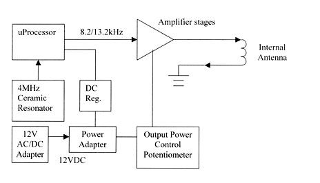
Block Diagram
Containment/Room Free Transmitter Block Diagrams uProcessor 10.7kHz Amplifier stages Internal Antenna 4MHz Ceramic Resonator 12V AC/DC Adapter DC Reg. 12VDC Output Power Control Potentiometer Power Adapter M0232xx Family:
Cover Letter(s)
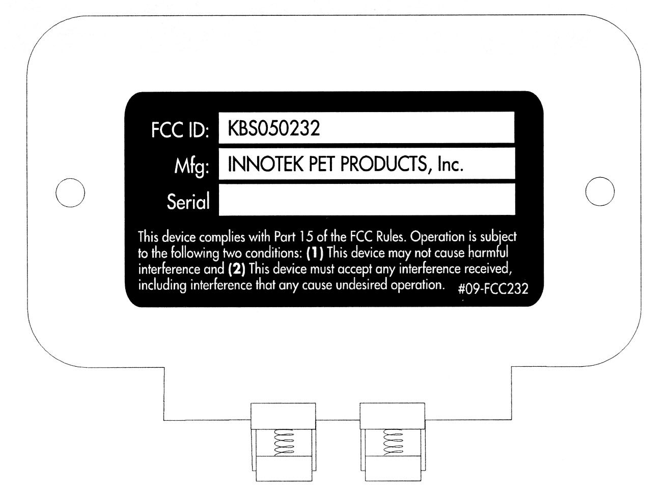
Responses to Non-Conformities (Ref # E00-000494-1) Item 1: There is a typo in the labeling statement in condition 2, should say “may caused” not “any caused”. [Section 15.19(a)(3)] There is also a typo in the Users Manual. Notice should state “if NOT installed and used in accordance with the instructions, may cause harmful interference to radio communications” or something similar. It currently states “if installed and used in accordance with the instructions, may cause harmful interference to radio communications.” Please see section 15.105(b). Please correct accordingly. DATE: 10/06/2000 17:25:11 Responses: 1)New label and manual uploaded Item 2: The 731 form states 11kHz. The block diagram and circuit description does not agree with what is stated on the 731 form. Please correct accordingly. DATE: 10/06/2000 17:25:11 Responses 2)New block diagram uploaded Please revise the 731 form to reflect frequency range of .009-.014MHz. The items indicated above must be submitted before processing can continue on the referenced application. Failure to provide the requested information within 60 days may result in application dismissal pursuant to Section 2.917(c) and forfeiture of the filing fee pursuant to Section 1.1106.
Operational Description
Containment Transmit Data Bit Timing/Encoding The figure below illustrates the timing used for data bit transmission: “ON” Time T B = 0 1.4ms ± .2 ms T B = 1 4.0ms ± .2 ms 8 msec T B Bit 0Bit 1Bit 2Bit 3Bit 4Bit 5Bit 6Bit 7 Bit 0 (Next Packet) 131ms 64ms
Operational Description
M023200 Functional Description: The M02320 family of transmitters are used in conjunction with various different Innotek collar receiver units to provide a means for repelling an animal from a specific area. The primary function of the circuit is to send out an 8-bit PWM coded word on one of two alternating frequencies (8.2kHz and 13.2kHz). This is accomplished via the microcontroller (U3) modulating the transistor/FET darlington ciruit (Q1, Q2, Q3) with the appropriate frequency for the proper pulse duration (a “0” is approximately 2ms wide and a “1” is approximately 4ms wide). The circuit puts out a word on the 8.2kHz frequency then puts out the same word on the 13.2kHz frequency 131ms later. This pattern repeats continuously while the unit is powered up. The field strength of the signal is controlled via adjusting the voltage using the potentiometer within S1. The ferrite (L1) acts as the radiating element for the circuit. Power and ground for the transmitter are provided by an external AC/DC transformer.
Operational Description
Compa ny Name:Innotek Inc Address:One Innoway, Garrett In, 46738 Device:Containment Transmitter Model Number(s):M023200 Briefly Describe Purpose of Device:The units transmit a coded signal used by a receiving unit (normally worn by a dog) to determine position relative to the transmitting antenna 1. Is your unit a Transmitter, Receiver or Transceiver? Transmitter 2. How many channels (frequencies)? 1 2a. What is the separation of those channels? 5kHz 3. What is the operating frequency(s)? 10.7kHz 4. Is this a spread spectrum device? No 4a. If yes, is it a direct sequencer or frequency hopper? N/A 5. What is the power output? TBD 6. What is the bandwidth of your operating frequency? TBD 7. Is your antenna removable? No 7a. What type of connector? Speaker cable type wire interface 7b. How many different antennas are available for sale with the unit? 1 7c. What is the gain of each antenna? TBD 8. Is the unit AC, DC or Battery Powered? DC 8a. What is the requirement? (i.e. 120VAC, 230 VAC, 24VDC, 9VDC battery, etc.) 12VDC 8b. What is the current requirement? (in amps) 200mA max for all units 9. What are the dimensions of the unit? 10. How many power cords or I/O cables of the same type are used with the unit? 1
Operational Description
M023200 Functional Description: The M02320 family of transmitters are used in conjunction with various different Innotek collar receiver units to provide a means for repelling an animal from a specific area. The primary function of the circuit is to send out an 8-bit PWM coded word on one of two alternating frequencies (8.2kHz and 13.2kHz). This is accomplished via the microcontroller (U3) modulating the transistor/FET darlington ciruit (Q1, Q2, Q3) with the appropriate frequency for the proper pulse duration (a “0” is approximately 2ms wide and a “1” is approximately 4ms wide). The circuit puts out a word on the 8.2kHz frequency then puts out the same word on the 13.2kHz frequency 131ms later. This pattern repeats continuously while the unit is powered up. The field strength of the signal is controlled via adjusting the voltage using the potentiometer within S1. The ferrite (L1) acts as the radiating element for the circuit. Power and ground for the transmitter are provided by an external AC/DC transformer.
Test Report
Page 1 of 27 Report No: FC00-087 INNOTEK PET PRODUCTS TEST REPORT FOR THE CONTAINMENT TRANSMITTER, M023200 FCC PART 15 SUBPART C SECTIONS 15.207 & 15.209 COMPLIANCE DATE OF ISSUE: AUGUST 29, 2000 PREPARED FOR: Innotek Pet Products One Innoway Garrett, IN 46738 W.O. No: 75021 PREPARED BY: Tracy Phillips CKC Laboratories, Inc. 5473A Clouds Rest Mariposa, CA 95338 Date of test: August 17, 2000 Report No: FC00-087 DOCUMENTATION CONTROL: _____________________________ Tracy Phillips Documentation Control Supervisor CKC Laboratories, Inc. APPROVED BY: _____________________________ Dennis Ward Director of Laboratories CKC Laboratories, Inc. This report contains a total of 27 pages and may be reproduced in full only. Partial reproduction may only be done with the written consent of CKC Laboratories, Inc. Page 2 of 27 Report No: FC00-087 TABLE OF CONTENTS Administrative Information ............................................................................................. 3 Summary Of Results........................................................................................................ 4 Equipment Under Test (EUT) Description...................................................................... 4 Measurement Uncertainty................................................................................................ 4 Peripheral Devices ........................................................................................................... 4 Report Of Measurements................................................................................................. 5 Table 1: Fundamental Emission Level ................................................................ 5 Table 2: Six Highest Spurious Emission Levels - 9 kHz - 1000 MHz ................ 6 Table 3: Six Highest Conducted Emission Levels .............................................. 7 Table A: List Of Test Equipment .................................................................................... 8 EUT Setup .......................................................................................................................9 Test Instrumentation And Analyzer Settings................................................................... 10 Table B: Analyzer Bandwidth Settings Per Frequency Range............................ 10 Spectrum Analyzer Detector Functions............................................................... 11 Peak ......................................................................................................... 11 Quasi-Peak............................................................................................... 11 Average.................................................................................................... 11 Test Methods ................................................................................................................... 11 Radiated Emissions Testing................................................................................. 12 Conducted Emissions Testing ............................................................................. 12 Sample Calculations ........................................................................................................ 13 Appendix A: Information About The Equipment Under Test......................................... 14 I/O Ports............................................................................................................... 15 Crystal Oscillators ............................................................................................... 15 Printed Circuit Boards ......................................................................................... 15 Photograph Showing Radiated Emissions ........................................................... 16 Photograph Showing Radiated Emissions ........................................................... 17 Photograph Showing Conducted Emissions........................................................ 18 Photograph Showing Conducted Emissions........................................................ 19 Appendix B: Measurement Data Sheets .......................................................................... 20 Page 3 of 27 Report No: FC00-087 CKC Laboratories, Inc. has Certificates of Accreditation from the following agencies: DATech (Germany); A2LA (USA); FCC (USA); VCCI (Japan); BSMI (Taiwan); HOKLAS (Hong Kong). CKC Laboratories, Inc. has Letters of Acceptance through an MRA for the following agencies: ACA/NATA (Australia); SABS (South Africa); SWEDAC (Sweden); TUV Rheinland-Germany; TUV Rheinland- Korea; TUV Rheinland-Russia; Radio Communications Agency (RA); NEMKO (Norway). ADMINISTRATIVE INFORMATION DATE OF TEST: August 17, 2000 PURPOSE OF TEST: To demonstrate the compliance of the Containment Transmitter, M023200, with the requirements for FCC Part 15 Subpart C Sections 15.207 & 15.209 devices. MANUFACTURER: Innotek Pet Products One Innoway Garrett, IN 46738 REPRESENTATIVE: Pete Johnson TEST LOCATION: CKC Laboratories, Inc. 22105 Wilson River Hwy Tillamook, OR 97141 TEST PERSONNEL: Mike Wilkinson TEST METHOD: ANSI C63.4 1992 FREQUENCY RANGE TESTED: 9 kHz - 1000 MHz EQUIPMENT UNDER TEST: Pet Containment Transmitter Manuf:Innotek Pet Products Model:M023200 Serial:023201 I 001798 FCC ID:KBS050232 (Pending) Power Supply Manuf:Inotek Pet Products Model:HD-1220 Serial:N/A FCC ID:N/A Page 4 of 27 Report No: FC00-087 SUMMARY OF RESULTS The Innotek Pet Products Containment Transmitter, M023200, was tested in accordance with ANSI C63.4 1992 for compliance with FCC Part 15 Subpart C Sections 15.207 & 15.209. As received, the above equipment was found to be fully compliant with the limits of FCC Part 15 Subpart C Sections 15.207 & 15.209. The results in this report apply only to the items tested, as identified herein. EQUIPMENT UNDER TEST (EUT) DESCRIPTION The units transmit a coded signal used by a receiving unit (normally worn by a dog) to determine position relative …
Text truncated - open the document above for the full version.
Test Setup Photos
Page 1 of 27 Report No: FC00-087 INNOTEK PET PRODUCTS TEST REPORT FOR THE CONTAINMENT TRANSMITTER, M023200 FCC PART 15 SUBPART C SECTIONS 15.207 & 15.209 COMPLIANCE DATE OF ISSUE: AUGUST 29, 2000 PREPARED FOR: Innotek Pet Products One Innoway Garrett, IN 46738 W.O. No: 75021 PREPARED BY: Tracy Phillips CKC Laboratories, Inc. 5473A Clouds Rest Mariposa, CA 95338 Date of test: August 17, 2000 Report No: FC00-087 DOCUMENTATION CONTROL: _____________________________ Tracy Phillips Documentation Control Supervisor CKC Laboratories, Inc. APPROVED BY: _____________________________ Dennis Ward Director of Laboratories CKC Laboratories, Inc. This report contains a total of 27 pages and may be reproduced in full only. Partial reproduction may only be done with the written consent of CKC Laboratories, Inc. Page 2 of 27 Report No: FC00-087 TABLE OF CONTENTS Administrative Information ............................................................................................. 3 Summary Of Results.....................…
Text truncated - open the document above for the full version.
Contact Information
Applicant
Clifton P Brick(Product Safety and Regulatory Manager)
Technical Contact
CKC Laboratories, Inc.Tracy Phillips
[email protected]800 500 4362
5473A Clouds Rest · Mariposa, California · United States
Non-Technical Contact
CKC Laboratories, Inc.Joyce Walker
[email protected]800 500 4362
Test Firm
CKC Laboratories, Inc.Steve Behm
Technical Specifications
| # | Rule Parts | Frequency Range | Power Output |
|---|---|---|---|
| 1 | 15C | 0.009 MHz - 0.014 MHz | - |
Other Applications from Radio Systems Corporation
KBS050237
Apr 16, 2003M023700 Transmitter
Equipment Class
DXX - Part 15 Low Power Communication Device Transmitter
KBS050210
Oct 17, 2000Pet Containment System M021000
Equipment Class
DCD - Part 15 Low Power Transmitter Below 1705 kHz
KBS050229
Oct 17, 2000Pet Containment System M022900
Equipment Class
DCD - Part 15 Low Power Transmitter Below 1705 kHz
KBS050238
Apr 25, 2000Wireless Fence Transmitter, WF-020
Equipment Class
DXX - Part 15 Low Power Communication Device TransmitterKBS-050460
Dec 22, 1992FDS - Part 15 Field Disturbance Sensor
Equipment Class
FDS - Part 15 Field Disturbance Sensor