KDYDGPR915Proximity reader and keypad
Paradox Security Systems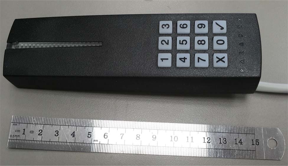
Click to zoom
Application Details
- Equipment Class
- DCD - Part 15 Low Power Transmitter Below 1705 kHz
- Date of Grant
- Oct 06, 2014
- Application Purpose
- Original Equipment
- Date of Application
- Oct 06, 2014
- Equipment Note
- Proximity reader and keypad
- Frequency Range
- 0.12700000 - 0.12700000
- Company
- Paradox Security Systems
- Country
- Canada
Documents & Files
Document Text
Text extracted from the exhibit documents filed with the FCC. Open a document above to read the original.
Users Manual
ENGLISH Introduction The R915 is a weatherproof 4-wire proximity card reader with a built- in backlit 12-button keypad for PIN entry. The R915 is compatible with any Digiplex or EVO control panel and is connected to a ACM12 using only 4 wires to facilitate installation. Keypad This reader can use both the Card and PIN functions. However, the PIN must be entered after the card is scanned if Card and PIN is enabled. You can also use the Card Only, PIN Only or Card or PIN settings, which are set in the ACM12. PIN settings are only available with ACM12 V4.0 or higher. The key is used to cancel a PIN entry, the key is used when using Flexible Code Length and entering a code shorter than 6 digits. Arming and Disarming It is currently possible to arm and disarm the system if the proper options are enabled in the User and door’s settings. Refer to your EVO programming guide for additional information. Tricolour LED Display The reader includes a tricolour LED display (red, green and amber) that is used to indicate system status as shown in the LED display table. Audible Tone The reader includes a built in beeper. Weather Resistant The rubber gasket and plastic PCB cover allows you to mount your R915 indoors or outdoors. Technical Specifications All specifications are subject to change without notice. Installation Mounting Mount the reader on a clean, flat and even surface to avoid bending the plastic casing. Once mounted, properly seal the reader’s contour to avoid possible water infiltration. ETL NOTE: Mount this reader in a protected/supervised location. It is highly recommended to mount the reader on a flat, even surface, thereby making it less vulnerable to weather damage. If mounting on an uneven surface is absolutely necessary, ensure that all gaps between the reader and surface are properly sealed. Mounting on Metal Metal may decrease the read range. The card reader can be mounted on metal but do not surround it by metal. If the reader must be installed in a metal enclosure, ensure that the face of the card reader is not covered and that there is at least 4cm (1.6") between the card reader and the metal on all sides. Connection Connect the R915 as shown in Figure 1. Status Display ESPAÑOL Introducción El R915 es un lector de tarjetas de proximidad de 4 cables a prueba de intemperies con un teclado incorporado de 12 botones con luz de fondo para el ingreso de un NIP. El R915 es compatible con cualquier central Digiplex o EVO y es conectado a un módulo ACM12 mediante sólo 4 cables para facilitar la instalación. Teclado Este lector puede usar las funciones de Tarjeta y de NIP conjuntamente. Sin embargo, el NIP debe ser ingresado después de la lectura de la tarjeta por el lector si ambas funciones de Tarjeta y NIP están habilitadas. También se puede usar las funciones de Sólo Tarjeta, Sólo NIP o las funciones de Tarjeta o NIP, que son definidas en el ACM12. La configuración del NIP sólo está disponible con el módulo ACM12 versión 4.0 o posterior. La tecla es usada para anular el ingreso de un NIP, la tecla es usada cuando se emplea la opción de Extensión Flexible de Código y se ingresa un código de menos de 6 dígitos. Armado y Desarmado Actualmente, es posible armar y desarmar el sistema si las opciones adecuadas están habilitadas en las configuraciones de usuario y de puerta. Consultar la guía de programación de EVO para más información. Indicador LED Tricolor El lector incluye un indicador LED tricolor (rojo, verde y ámbar) que se usa para indicar el estado del sistema como se muestra en la tabla de indicadores LED. Tono Audible El lector incluye un avisador con tonos incorporado. A prueba de Intemperies La junta de caucho y la cubierta en plástico PCB permiten el montaje del R915 en interiores o exteriores. Especificaciones Técnicas Todas las especificaciones pueden cambiar sin previo aviso. Instalación Montaje Montar el lector sobre una superficie plana, limpia y pareja para evitar el doblado de la caja plástica. Una vez montado, sellar correctamente el contorno del lector para evitar la infiltración del agua. Se recomienda enfáticamente montar el lector en una superficie plana y pareja, lo que lo hace menos vulnerable a a las intemperies. Si el montaje en una superficie irregular es absolutamente necesario, asegurarse de sellar todos los espacios vacios que se encuentren entre el lector y la superficie. Montaje Sobre Metal El metal podría reducir el alcance de lectura. El lector de tarjetas puede ser montado sobre metal pero no debe estar rodeado de metal. Si el lector debe ser instalado en una caja metálica, verificar que nada cubra su parte frontal y de mantener una distancia de por lo menos 4cm (1.6") entre el lector de tarjetas y el metal, por todos lados. Conexión Conectar el R915 como se muestra en la Figura 2. Pantalla de Estado Compatibility Card only: DGP-ACM11 version 3.0 or higher Card/PIN: ACM12 version 4.0 or higher Power Input:11Vdc to 14.5Vdc Current Consumption60mA Frequency:Exciter field 125 KHz Pulse Modulated Operating Temperature:-35°C (-31°F) to +65°C (149°F) Output Formats:4-wire (RS-485) Cable Distance:300m (1000 ft.) Cables:4-wire Cables (Twisted Pair recommended) Color: Available in black, white and silver Weather ProofingRubber Gasket and Plastic PCB cover. R915 V1.0 4-Wire Sealed Indoor/Outdoor Proximity Reader and Keypad PARADOX.COM Printed In Canada - 10/2010 R915-TI01 Status Visual Indicators* Audible Tone Green Red Amber Access Wait for PIN entry Slow Flash--- Read Card-- On when reading Fast Beep Access Denied-Fast Flash- Long Beep Access GrantedOn--Fast Beep Door UnlockedOn--- Door Locked-On-- Door Left Open Pre-Alarm -Flash-Beep Door Left/ Forced Open -Fast Flash-Fast Beep Security Fire Alarm-Pulsed-Pulsed Burglary Alarm-Flash-Beep Armed-Fast Flash- Exit Delay-Flash†-Beep† Trouble shooting Fail to Com.Slow Alternating Flash -- Safe Mode Alternating Flash with Pause -- Lost Communication with ACM11 -- Slow Flash - LocateFast Flash--- * Certain displays can…
Text truncated - open the document above for the full version.
Cover Letter(s)
Ref: Authori zation Letter _ SD360_PMD2P_R915 To: Hermon Labs Declaration of Authorization We, Paradox Security Systems 780 INDUSTRIAL BLVD ST-EUSTACHE, QC, CANADA J7R 5V3 Phone: 450-491-7444 Fax: 450-491-1095 Declare that Hermon Laboratories Ltd. Harakevet Industrial Zone Binyamina 30500 Israel is authorized to apply for Certification of the following products: Product description: Proximity reader and keypad Type designation: R915 Trademark: Paradox on our behalf. Jul-31-2014 Nimrod Herman Certification Manager
Cover Letter(s)
FCC, Request for non-disclosure Date: 16-Jul-10 RF_501, Issue 6 Page 1 of 1 Company Name: Paradox Security Systems Address : 780 Industriel Blvd City: Saint-Eustache, QC, J7R 5V3 Country: Canada To: Telefication B.V., Dept. FCC TCB Edisonstraat 12A 6902 PK ZEVENAAR The Netherlands Subject: Request for confidentiality FCC ID: KDYDGPR915 Reference number: ###### Dear FCC TCB, 1. Long-Term Confidentiality Pursuant to 47 CFR Section 0.459(a) & (b), we hereby requests non-disclosure and confidential treatment of the following materials submitted in support of FCC certification application: Bill(s) of Material Block Diagrams Operational Description Schematic Diagrams Tune-up Procedure Above materials contain secrets, proprietary and technical information, which would customarily be guarded from competitors under 47 CFR, section 0.457(d)(2). Disclosure or publication or any portion of this company confidential material to other parties could cause substantial competitive harm and provide unjustified benefits for competitors. 2. Short-Term Confidentiality (STC) Pursuant to Public Notice DA 04-1705 of the Commission’s policy, in order to comply with the marketing regulations in 47 CFR §2.803 and the importation rules in 47 CFR §2.1204, a pplicant hereby requests Short-Term Confidential treatment of the following materials (note 1): Internal Photos User’s Manual Test Set-up Photos External Photos Justification: Patent Pending. Competative advantage Planned Release Date STC: 180 days from the grant date (notes 2, 3, 4, 5) Date: July 31, 2014 Name and signature of applicant: Nimrod Herman Notes: 1) A document or type of document can only have ONE type of confidentiality! 2) Short-Term confidentiality is in principle for 45 days from date of grant; it can be extended max 3 times (total time 180 days max.)! 3) FCC must be informed when marketing begins earlier. 4) Release takes place automatically thus extension must be requested in time. Telefication does not remind you of this! 5) Request for extension or for release must be received by Telefication at least 7 days before date of actual marketing or before expiration of the STC period
External Photos
Paradox Security Systems Ltd. FCC ID: KDYDGPR915 IC:2438A-DGPR915 Page 1 of 3 EXTERNAL PHOTOGRAPHS This document contains 2 photographs Paradox Security Systems Ltd. FCC ID: KDYDGPR915 IC:2438A-DGPR915 Page 2 of 3 Photograph No.1 R915 proximity reader and keypad front view Paradox Security Systems Ltd. FCC ID: KDYDGPR915 IC:2438A-DGPR915 Page 3 of 3 Photograph No.2 R915 proximity reader and keypad rear side view
ID Label/Location Info
Paradox Security Systems Ltd. FCC ID: KDYDGPR915 IC:2438A-DGPR915 Page 1 of 1 Label The label shown below is affixed on the rear side of the proximity reader. The label material is PVC with a permanent adhesive. Label location Label with FCC ID:KDYDGPR915 and IC:2438A-DGPR915 will be located at the rear side panel. The statement according to FCC part 15 §15.19(a)(3) is placed in User Manual, page 2 (Application exhibit User_manual_25767). FCC ID:KDYDGPR915 IC:2438A-DGPR915
Internal Photos
Paradox Security Systems Ltd. FCC ID: KDYDGPR915 IC:2438A-DGPR915 Page 1 of 5 INTERNAL PHOTOGRAPHS This document contains 4 photographs Paradox Security Systems Ltd. FCC ID: KDYDGPR915 IC:2438A-DGPR915 Page 2 of 5 Photograph No.1 R915 proximity reader and keypad internal view Paradox Security Systems Ltd. FCC ID: KDYDGPR915 IC:2438A-DGPR915 Page 3 of 5 Photograph No.2 R915 proximity reader and keypad main PCB front view Paradox Security Systems Ltd. FCC ID: KDYDGPR915 IC:2438A-DGPR915 Page 4 of 5 Photograph No.3 R915 proximity reader and keypad main PCB second side view Paradox Security Systems Ltd. FCC ID: KDYDGPR915 IC:2438A-DGPR915 Page 5 of 5 Photograph No.6 Antenna close view
Test Report
Hermon Laboratories Ltd. Harakevet Industrial Zone, Binyamina 30500, Israel Tel. +972-4-6288001 Fax. +972-4-6288277 E-mail: [email protected] Page 1 of 40 Report ID: PARRAD_FCC.25767_rev1.docx Date of Issue: 6-Aug-14 ELECTRICAL TESTING 0839.01 TEST REPORT ACCORDING TO: FCC 47CFR part 15 subpart C § 15.209 and subpart B; RSS-210 issue 8 section 2.5.1, RSS-Gen issue 3, ICES-003 Issue 5:2012 FOR: Paradox Security Systems Proximity reader and Keypad Model: R915 FCC ID:KDYDGPR915 IC:2438A-DGPR915 This report is in conformity with ISO/ IEC 17025. The "A2LA Accredited" symbol endorsement applies only to the tests and calibrations that are listed in the scope of Hermon Laboratories accreditation. The test results relate only to the items tested. This test report shall not be reproduced in any form except in full with the written approval of Hermon Laboratories Ltd. Report ID: PARRAD_FCC.25767_rev1.docx Date of Issue: 6-Aug-14 Page 2 of 40 Table of contents 1 Applicant information ..................................................................................................................................................... 3 2 Equipment under test attributes .................................................................................................................................... 3 3 Manufacturer information .............................................................................................................................................. 3 4 Test details .................................................................................................................................................................... 3 5 Tests summary .............................................................................................................................................................. 4 6 EUT description ............................................................................................................................................................. 5 6.1 General information ....................................................................................................................................................... 5 6.2 Ports and lines .............................................................................................................................................................. 5 6.3 Support and test equipment .......................................................................................................................................... 5 6.4 Changes made in EUT .................................................................................................................................................. 5 6.5 Test configuration .......................................................................................................................................................... 6 7 Transmitter tests according to 47CFR part 15 subpart C and RSS-210 requirements ................................................. 7 7.1 Field strength of emissions ............................................................................................................................................ 7 7.2 Antenna requirements ................................................................................................................................................. 15 7.3 Occupied bandwidth test ............................................................................................................................................. 16 7.4 Conducted emissions .................................................................................................................................................. 19 8 Unintentional emissions .............................................................................................................................................. 22 8.1 Conducted emissions .................................................................................................................................................. 22 8.2 Radiated emission measurements .............................................................................................................................. 26 9 APPENDIX A Test equipment and ancillaries used for tests ....................................................................................... 31 10 APPENDIX B Measurement uncertainties ................................................................................................................... 32 11 APPENDIX C Test laboratory description ................................................................................................................... 33 12 APPENDIX D Specification references ....................................................................................................................... 33 13 APPENDIX E Test equipment correction factors ......................................................................................................... 34 14 APPENDIX F Abbreviations and acronyms ................................................................................................................. 40 Report ID: PARRAD_FCC.25767_rev1.docx Date of Issue: 6-Aug-14 Page 3 of 40 1 Applicant information Client name: Paradox Security Systems Address: 780 Industriel BLVD, St-Eustache, QC, J7R 5V3, Canada Telephone: 450-491-7444 Fax: 450-491-1095 E-mail: [email protected] Contact name: Mr. Nimrod Herman 2 Equipment under test attributes Product name: Proximity reader and Keypad Product type: Transceiver Model(s): R915 Serial number: 12B304EB Hardware version: 671-2122-020 Software release: V1.01 Receipt date 28-Jul-14 3 Manufacturer information Manufacturer name: Paradox Security Systems Address: 780 Industriel BLVD, St-Eustache, QC, J7R 5V3, Canada Telephone: 450-491-7444 Fax: 450-491-1095 E-Mail: [email protected] Contact name: Mr. Nimrod Herman 4 Test details Project ID: 25767 Location: Hermon La…
Text truncated - open the document above for the full version.
Test Setup Photos
Paradox Security Systems Ltd. FCC ID: KDYDGPR915 IC:2438A-DGPR915 Page 1 of 6 SETUP PHOTOGRAPHS This document contains 5 photographs Paradox Security Systems Ltd. FCC ID: KDYDGPR915 IC:2438A-DGPR915 Page 2 of 6 Photograph No.1 Setup for spurious emission field strength measurements in the anechoic chamber below 30 MHz Paradox Security Systems Ltd. FCC ID: KDYDGPR915 IC:2438A-DGPR915 Page 3 of 6 Photograph No.2 Setup for carrier field strength, spurious emission field strength measurements in the anechoic chamber in 30 – 1000 MHz range Paradox Security Systems Ltd. FCC ID: KDYDGPR915 IC:2438A-DGPR915 Page 4 of 6 Photograph No.3 Setup for spurious emission field strength measurements in the anechoic chamber, EUT close view Paradox Security Systems Ltd. FCC ID: KDYDGPR915 IC:2438A-DGPR915 Page 5 of 6 Photograph No.4 Setup for conducted emission measurements on AC power lines Paradox Security Systems Ltd. FCC ID: KDYDGPR915 IC:2438A-DGPR915 Page 6 of 6 Photograph No.5 Setup for conducted emission measurements on AC power lines
Contact Information
Applicant
Alex Chaplik(Certification Manager)
Technical Contact
Hermon Laboratories Ltd.Michael Nikishin
[email protected]97246268440
Harakevet Industrial zone, P.O.Box 23 · Israel
Non-Technical Contact
Paradox Security SystemsNimrod Herman
[email protected]97248500499
Test Firm
Hermon Laboratories Ltd.Alexander Usoskin
Technical Specifications
| # | Rule Parts | Frequency Range | Power Output |
|---|---|---|---|
| 1 | 15C | 0.127 MHz - 0.127 MHz | - |
Other Applications from Paradox Security Systems
KDYX45
May 07, 2026Hybrid Head Unit/Console
Equipment Class
DSS - Part 15 Spread Spectrum TransmitterKDYZP2M
Dec 23, 2025Dual Input /Output Wireless Bus Expander Two Garage Door
Equipment Class
DSS - Part 15 Spread Spectrum TransmitterKDYK70M
Dec 12, 20257 inch Touchscreen Keypad
Equipment Class
DTS - Digital Transmission SystemKDYDCT12M
Nov 25, 2025Door /Window Magnetic Contact + Zone
Equipment Class
DSS - Part 15 Spread Spectrum Transmitter
KDYPGM8M
Nov 25, 2025PGM Expander
Equipment Class
DSS - Part 15 Spread Spectrum Transmitter