KDYMGDCT10Door Contact Transmitter
Paradox Security Systems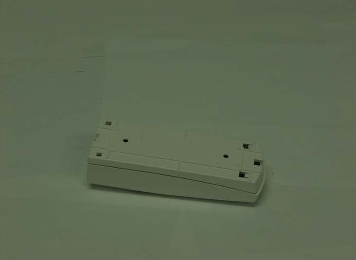
Click to zoom
Application Details
- Equipment Class
- DSC - Part 15 Security/Remote Control Transmitter
- Date of Grant
- Jul 23, 2007
- Application Purpose
- Original Equipment
- Date of Application
- Jul 22, 2007
- Equipment Note
- Door Contact Transmitter
- Frequency Range
- 433.92000000 - 433.92000000
- Company
- Paradox Security Systems
- Country
- Canada
Documents & Files
Document Text
Text extracted from the exhibit documents filed with the FCC. Open a document above to read the original.
Users Manual
MGDCT10-TI04 www.paradox.com Printed in Canada - 03/2007 Instructions Instrucciones Wireless 2-Zone Door Contact (Universal Transmitter) MG-DCT10 V2.2 Do not connect an EOL resistor to the universal transmitter input. Do not cut, bend or alter the antenna. Avoid mounting the door contact near or on metal as this may affect transmission. Location & MountingThere should be at least 30cm (1ft) between each transmitter and 1.5m (5ft) between the transmitters and the receiver. The transmitter comes with two reed switches allowing you to place the transmitter either vertically or horizontally. Simply place the magnet in line with the reed switch you wish to use. The other reed switch and the universal transmitter input will automatically be disabled. Jumpers Magellan Receiver Omnia Receiver JP1 ON Reed Switch N.O.: open = “zone open” signalclosed = “zone closed” signal Check-in Supervision:12 hours OFF Reed Switch N.C.: open = “zone closed” signalclosed = “zone open” signal Check-in Supervision:12 minutes JP2 ON Magellan protocol Magellan protocol OFF Omnia protocol Omnia protocol JP3 ON Universal Input N.O.: open = “zone open” signalclosed = “zone closed” signal N/A OFF Universal Input N.C.: open = “zone closed” signalclosed = “zone open” signal N/A After changing the jumper settings, press and release the anti- tamper switch in order to save the changes. Learn ModeLearn Mode allows you to transmit the serial numbers of each input. To enter Learn Mode, open the cover and wait until the LED stops flashing. Input Serial Number Visual Confirmation Input 1 (reed switch): Press the anti-tamper switch once. SN (e.g. 240 000) The LED will flash once four times. Input 2 (universal input): Press the anti-tamper switch twice within one second. SN+1 (e.g. 240 001) The LED will flash twice rapidly four times. English The MG-DCT10 can support two inputs simultaneously (reed switch & universal input). When using the MG-DCT10 in conjunction with a Magellan receiver, it will transmit two different serial numbers (SN), one for each input, which are always SN and SN+1(e.g. 240 000 & 240 001). When using it in conjunction with an Omnia receiver, it will transmit only one serial number (either reed switch or universal transmitter). A switch or other security device can be connected to the universal transmitter input terminals to provide wireless transmission of the device's open/closed status. Testing the Unit1. Perform a signal strength test before finalizing installation. If the transmission is weak, relocate the transmitter by a few inches to improve reception. 2. Verify that the batteries are inserted properly. 3. Assign the door contact to a Magellan receiver. 4. Open and close the assigned door/ window to verify proper operation. Technical Specifications Reed switch w/magnet Two (high sensitivity) with a standard gap of 1cm (0.4”) from magnet Input Response Time 45 ms RF frequency 433MHz or 868MHz Power 4.5Vdc (Three “AAA” Alkaline batteries) * Battery life Up to three years ** Range (typical in a residential environment) MG5000/MG-RCV3/1759MG: 70m (230ft) MG-6160/MG-6130, MG-6060/MG-6030: 30m (100ft) OMN-RCV3: 150m (500ft) Anti-tamper switch Yes Compatibility Magellan Protocol: MG-6160, MG-6130, MG-6060, MG-6030, MG5000, MG-RCV3, 1759MG Omnia Protocol: OMN-RCV3 and 1759EX Dimensions 12.5cm X 4.6cm X 2.5cm (4.9in X 1.8in X 1.0in) Operating temperature 0°C to 49°C (32°F to 120°F) Approvals † 433MHz 868MHz Powering the Unit Low Battery Battery Replacement Verify proper polarity and insert three alkaline “AAA” batteries. After inserting batteries, a power up sequence will begin (10-20 seconds) during which the door contact will not detect an open zone or tamper. The MG-DCT10 performs a bat-tery test every 12 hours. If the volt-age is below 2.3V after four consecutive battery tests (48 hrs.), the red LED will flash at 5 second intervals and the MG-DCT10 will transmit a low battery signal. To replace batteries:1. Replace the old batteries with new ones. 2. Press and release the anti-tamper switch several times. 3. Wait 60 seconds to reinitialize the unit. JP3JP2JP1 Ubicación y MontajeDebe haber una distancia de por lo menos 30cm (1ft) entre cada transmisor y 1.5m (5ft) entre los transmisores y el receptor. El transmisor tiene dos interruptores de lámina lo que permite ubicar el transmisor vertical o horizontalmente. Simplemente alinee el imán con el interruptor de lámina que desea usar. El otro interruptor de lámina y la entrada de transmisor universal serán deshabilitados automáticamente. Español El MG-DCT10 puede aceptar dos entradas simultáneamente (entrada de interruptor de lámina y entrada universal). Al usar el MG-DCT10 junto a un receptor Magellan, el contacto transmite dos números de serie diferentes (NS), uno por cada entrada, los que son siempre NS y NS+1 (i.e. 240 000 y 240 001). Al usar junto a un receptor Omnia, el contacto transmite sólo un número de serie (interruptor de lámina o transmisor universal). Un interruptor u otro dispositivo de seguridad puede ser conectado a los terminales de entrada de transmisor universal para obtener transmisión inalámbrica del estado de abierto/cerrado del dispositivo. Prueba de la Unidad1. Efectuar una prueba de fuerza de la señal antes de terminar la instalación. Si la transmisión es débil, mover el transmisor tan sólo unos pocos centímetros para mejorar la recepción. 2. Verificar si la batería ha sido insertada correctamente. 3. Asignar el contacto de puerta a un receptor Magellan. 4. Abrir y cerrar la puerta o ventana asignada para comprobar el buen funcionamiento. No conectar una resistencia RFL a la entrada de transmisor universal. No se debe cortar, doblar o alterar la antena. Evitar ubicar el contacto de puerta cerca de o sobre metal pues esto podría afectar la transmisión Puentes Receptor Magellan Receptor Omnia JP1 ON Interruptor de Lámina N.A.: abierto = señal de “zona abierta”cerrado = señal de “zona cerrada” Verificación de Presencia:12 Horas OFF Inte…
Text truncated - open the document above for the full version.
Block Diagram
Battery Pack 3X "AAA" Reed switch and tamper Micro controller Internal clock 4MHz Transmitter Filtering/matching MG-DCTXP Antenna 13.56MHz or 27..13594MHz MG-DCT1
Cover Letter(s)
March 29th, 2007 Nemko Canada Inc 303 River Road Ottawa, Ontario, Canada K1V 1H2 Attn: Director of Certification Authority to Act as Agent On our behalf, I appoint Nemko Canada Inc. to act as our agent in the preparation of this application for equipment certification. I certify that submitted documents properly describe the device or system for which equipment certification is sought. I also certify that each unit manufactured, imported or marketed, as defined in the Federal Communications Commission’s regulations will have affixed to it a label identical to that submitted for approval with this application. For instances where our authorized agent signs the application for certification on our behalf, I acknowledge that all responsibility for complying with the terms and conditions for certification, as specified by Nemko Canada Inc, still resides with Paradox Security Systems, 780 Industrial Blvd, St-Eustache, Quebec, CANADA, J7R 5V3 Dated this 29th Day of March 2007 Agency agreement expiration date: December 31 st 2007 By: NABIL NAHOUL Signature Printed Title: Certification Manager On behalf of : Paradox Security Systems Telephone: (450) 491-7444 ext 209
Cover Letter(s)
March 29th, 2007 Equipment Autorisation Division Federal Communications Commission 7435 Oakland Mills Road Columbia, MD 21046 FCC ID: KDYMGDCT10 Product Name: Magelan model MGDCT10 Request for Confidentiality Pursuant to Sections 0.457 and 0.459 of the commissions rules, we hereby request that the following documents be held confidential: • Schematics • Block diagram • Operational description These materials contain trade secrets and proprietary information and are not customarily released to the public. The public disclosure of this information might be harmful to the company and provide unjustified benefits to our competitors. Dated this 29th Day of March 2007 By: NABIL NAHOUL Signature Printed Title: Certification Manager On behalf of : Paradox Security Systems Telephone: (450) 491-7444 ext 209
External Photos
External photos for DCT10
Operational Description
Description of the Blocks 1. The unit is powered with two “AAA” common alkaline battery type. 2. The microcontroller is the heart of the unit and controls the behavior of all functionalities as well as reports any changes in the state of the unit i.e.: Low battery, detection of intrusion, etc. Its internal clock frequency is 4MHz 3. The reed switch, external switch connector and tamper switch are the security features of the units: there is one reed switch, one connection for an external reed switch or any other dry contact (one independent serial number is assigned to each of them) and there is a tamper switch that sends an alarm in case of an attempt to open the casing of the unit. 4. The transmitter is a RF modulator that is modulating its amplitude by succeeding on and off state of its RF energy (OOK, On and Off keying), the baud rate is about 2.5kbaud/s Battery Pack 3X "AAA" Reed switch and tamper Micro controller Internal clock 4MHz TransmitterFiltering/matching MG-DCTXP Antenna 13.56MHz or 27..13594MHz MG-DCT1 5. The transmitter uses a PLL (phase locked loop) which use a divider by 32 for the sampling of its main frequency VCO (voltage controlled oscillator) and is compared against a crystal of the same divided frequency. So the output of the transmitter is 32 times the frequency of the crystal it uses. We have two model of transmitter for this unit, one for the output frequency of 433.92MHz and one for 868.35 MHz which lead to a crystal frequency of 13.56MHz for the 433.92MHz IC and 27.13594MHz for the 868.35MHz transmitter. 6. There is a filtering and matching circuit for the maximum transfer of energy to the antenna which consists of capacitors and inductors. 7. The output is hooked to helicoids antennas with an appropriate length according to the frequency it have to transmit.
Parts List/Tune Up Info
QTY REFERENCE VALUE PARADOX# DESCRIPTION SUPPLIER CATALOGUE# 1 PCB 312-4004-080 3124004080 MAGELLAN 433/868 DOOR CONTACT PCB ONPRESS PRINTED CIRCUITS LIMITED 312-4004-080-R ( 2 LAYER ) 1 ANT2 ANTPAD_COIL 1250433210 ANTENNA SPRING BRASS TIN PLAT 0.420" DIA. FORESIGHT ENT.,LTD. 312-4004-110T REV A 1 BT1 4.5V BATTERY 0771300315 BATTERY 1.5V AAA DURACELL GCL SOLUTIONS GROUP MN2400BKV 0740108043 HOLDER BATTERY AAAX3 COMFORTABLE ELECTRONIC CO.,LTD. BHC-43PAR REV.2 6 C1,L103,L104,C110,C111,C112 N/U 2 C2,C6 10nF 2101030603 CAP 0603, 10NF X7R 10% SAMSUNG C/O C.S.C. CL10B103KB8NNND 2 C5,C100 100nF 2101040603 CAP 0603, 100NF X7R 10% 16V SAMSUNG C/O C.S.C. CL10B104KO8NNND 4 C101,C103,C107,C109 100pF 2101010603 CAP 0603, 100PF SAMSUNG C/O C.S.C. CL10C101JB8NNND 1 C102 150pF 2101510603 CAP 0603, 150PF NPO 10% SAMSUNG C/O C.S.C. CL10C151KBNC 1 C104 5.6pF 2105060603 CAP 0603, 5.6PF +/-0.25PF NPO SAMSUNG C/O C.S.C. CL10C5R6CB8ANND 1 C105 330pF 2103310603 CAP 0603, 330PF SAMSUNG C/O C.S.C. CL10C331JB8NNND 1 C106 12pF 2101200603 CAP 0603, 12PF NPO 5% SAMSUNG C/O C.S.C. CL10C120JB8NNND 1 C108 1.5nF 2101520603 CAP 0603, 1.5NF SIMCONA MA0603XR152K500 (MERITEK) 1 D1 1SR154-400 2210400010 DIODE RECTIFIER SMD 400V DIODES INC. C/O GMA S1G-13-F 13" REELS ONLY 1 F1 200mA(SMT) 2050020100 PTC 200MA SMT BOURNS C/O PIPE THOMPSON TECHNO L MF-MSMF020-2 3 JP1,JP2,JP3 JUMPER 2401000000 JUMPER ASSEMBLED ON HEADER PINREX TECHNOLOGY CORP. 21S-91-02GB01 1 LED1 RED 2221601200 LED SMD RED 1206 SEOUL SEMICONDUCTOR C/O C.S.C SSCUR201TS 13" REEL ONLY 1 L100 27nH 2290027603 INDUCTOR 27NH 0603 SAMSUNG C/O C.S.C. CIH10T27NJNC 1 L102 33nH 2290033603 INDUCTOR 33NH 0603 SAMSUNG C/O C.S.C. CIH10T33NJNC 1 P2 REED CONNECTO R 2400015002 CON. 2PIN 5MM JITE CONNECTORS INC. JTB450-12-1-02-1-M2 1 R101 22K 2002230603 RES 0603 5%,22K SAMSUNG C/O C.S.C. RC1608J223AS 3 R3,R53,R54 1M5 2001550603 RES 0603 5%,1M5 SAMSUNG C/O C.S.C. RC1608J155AS (SAMSUNG) 1 R4 2K0 2002020603 RES 0603 5%,2K0 SAMSUNG C/O C.S.C. RC1608J202AS 4 R6,R303,R304,R317 10K 2001030603 RES 0603 5%,10K SAMSUNG C/O C.S.C. RC1608J103AS 2 R17,R20 1K0 2001020603 RES 0603 5%,1K0 SAMSUNG C/O C.S.C. RC1608J102AS 1 R100 10R 2001000603 RES 0603 5%,10 OHM SAMSUNG C/O C.S.C. RC1608J100AS 1 R319 6K81_1% 2006811603 RES 0603 1%,6K81 SAMSUNG C/O C.S.C. RC1608F6811AS ( 13") 1 R320 8K06_1% 2008061603 RES 0603 1%,8K06 SAMSUNG C/O C.S.C. RC1608F8061AS ( 13") 1 S1 DIGITAL SWITCH 2502100004 SWITCH MICRO (DGTL) EXCEL CELL ELECTRONIC,CORP. EJF1152000 2 S2,S4 REED SWITCH 2505601120 SWITCH REED GR560 10/20 A.T.CUT&FORMED EXCEL CELL ELECTRONIC,CORP. 402-52202A 2 S3,S5 OPTION(SMT) 1 U3 TH72012 2337201200 TRANSMITTER ASK 433MHZ SMD MELEXIS C/O TECHTREK TH72012 1 U5 PIC16LF648A 2351664825 MICRO 16LF648A SSOP MICROCHIP TECHNOLOGIES INC. PIC16LF648AT-I/SSG 1 VR101 LMV431 2300431001 REG. LMV431 LOW VOLT. ADJ. SOT23-5 STMICROELECTRONICS CANADA INC TS431ILT 1 XTAL101 13.56MHZ(20PPM) 2171356020 X'TAL 13.56MHZ +/-20PPM (SMD) SIWARD INTERNATIONAL INC. XTL121020B-13.56-18 4008000100 BOX DOOR CONTACT MG-DCT1 STUART PACKAGING INC. BOX DOOR CONTACT 4001000100 DOOR CONTACT PLASTICSET MOLDEX PLASTICS & TOOL INC. DOOR CONTACT WHITE W/BRASS INSERT 1900051000 HEADED INSERT THREAD SIZE 4-40 ONYX INNOVALUE INC. THREAD 4-40(PRESS INSERT SER. 51) 4002000000 MAGNET DOOR WHITE ONYX INNOVALUE INC. PLASTIC HOLDER W/MAGNET & 3 SCREWS 0750018010 LABEL SERIAL NUMBER TRANSFERT THERMIQUE IMS SYSTEMES DE MARQUAGE INDUST R ET53007-01 (TRANSMARK 18P 1"X0.875") 19000002X3 PLASTIC BAG ZIPLOC 2X3 EMBALLAGES JEAN CARTIER 20209911 1900440020 SCREW M/S COMB PHIL/SLOT 4X40X5/16"ZINC INDUSTRIES D.S. MSPQ440516 PARADOX SECURITY SYSTEMS MG-DCT10 (312-4004-080) ECO#E033 JUN 19,2007 1 of 2 QTY REFERENCE VALUE PARADOX# DESCRIPTION SUPPLIER CATALOGUE# PARADOX SECURITY SYSTEMS MG-DCT10 (312-4004-080) ECO#E033 JUN 19,2007 2 of 2
Schematics
AA 1Reed Tamper ENABLE Universal DATATamper DATA ENABLEUniversal Reed BATT BATT BATT BATT BATT BATT BATT BATT BATT BATT TitleSize Document Number Rev Date: Sheet of ECO# Copyright ©Private and Confidential.Property of Paradox Security Systems. 312-4004-080 080 433MHz 4.5 Volts Door Contact (MG-DCT10) 780 Blvd IndustrielSt-Eustache, QuébecJ7R 5V3Tel: (450) 491-7444 B 11 Wednesday, January 24, 2007 2005 E033 TitleSize Document Number Rev Date: Sheet of ECO# Copyright ©Private and Confidential.Property of Paradox Security Systems. 312-4004-080 080 433MHz 4.5 Volts Door Contact (MG-DCT10) 780 Blvd IndustrielSt-Eustache, QuébecJ7R 5V3Tel: (450) 491-7444 B 11 Wednesday, January 24, 2007 2005 E033 TitleSize Document Number Rev Date: Sheet of ECO# Copyright ©Private and Confidential.Property of Paradox Security Systems. 312-4004-080 080 433MHz 4.5 Volts Door Contact (MG-DCT10) 780 Blvd IndustrielSt-Eustache, QuébecJ7R 5V3Tel: (450) 491-7444 B 11 Wednesday, January 24, 2007 2005 E033 TP31TP36 C100 and C101should be as closeas possible to theRFIC C101 closest **** For australia standard bandstop filter 867.84MHz harmonic. ******** Self test mode is TP12 - RB5 TP 15 must be kept onthis side of theresistor R17.This testpad is intendto avoid anytransmissionwhenever the μC activatethe RF IC and a transmission is notwanted on air.For testing jig purpose. * L102 & L104 must be one beside the otheron the width of the transmission line.The purpose is to get a more preciseinductor value if needed.Tx line Tx line L102 Anti-copper around antennaon both layer Top andbottom L104 Straight transmission line 60 mils R101 For FCC levelput 22K ** Internal oscillator is to be use Decoupling capacitoras close as possibleto the IC R319, R320 to be adjustedfor discharged batterieswith high ESR (requested byEmil) TP11TP11 R53 1M5 R53 1M5 L100 27nH L100 27nH BT1 W/HOLDER 4.5V BATTERY BT1 W/HOLDER 4.5V BATTERY TP12TP12 R10122KR10122K TP33TP33 L104N/UL104N/U 12 C1 NU(100UF/16V) C1 NU(100UF/16V) XTAL101 13.56MHZ(20PPM) XTAL101 13.56MHZ(20PPM) R610KR610K C10612pFC10612pF R201K0R201K0 2 1 3 S1 TPSWITCH2 S1 TPSWITCH2 JP3 NO/NC JP3 NO/NC RA2/AN2/Vref 1 RA3/AN3 2 RA4/T0CKI 3 RA5/ MCLR 4 Vss 5 Vss 6 RB0/INT 7 RB1 8 RB2 9 RB3/CCP1 10 RB4 11 RB5 12 RB6 13 RB7 14 Vdd 15 Vdd 16 RA6/OSC2/CLKOUT 17 RA7/OSC1/CLKIN 18 RA0/AN0 19 RA1/AN1 20 U5 PIC16LF648A/SSOP U5 PIC16LF648A/SSOP C5 100nF C5 100nF S5 OPTION(SMT) S5 OPTION(SMT) TP7TP7 TP14TP14 R4 2K0 R4 2K0 R3208K06 1%R3208K06 1%R3196K81 1%R3196K81 1% C110 N/U C110 N/U R171K0R171K0 C109100pFC109100pF C210nFC210nF A K LED1REDLED1RED R10010RR10010R TP4TP4 TP9TP9 TP15TP15 R31M5R31M5 C610nFC610nF C112 N/U C112 N/U R541M5R541M5 ENTX 4 ROI 3 n.c 2 ASKDTA 1 PSEL 5 VCC 6 OUT 7 VEE 8 U3 TH72012 U3 TH72012 C1045.6pFC1045.6pF S2 REED SWITCH S2 REED SWITCH TP10TP10 C111N/UC111N/U C105 330pF C105 330pF C100100nFC100100nF C1081.5nFC1081.5nF TP16TP16 R303 10K R303 10K TP6TP6 F1 200mA(SMT) F1 200mA(SMT) TP32TP32 TP8TP8 S4 REED SWITCH S4 REED SWITCH VR101LMV431-DUAL-FPVR101LMV431-DUAL-FP D1 1SR154-400 D1 1SR154-400 S3 OPTION(SMT) S3 OPTION(SMT) L102 33nH L102 33nH C107100pFC107100pF 1 1 2 2 P2 REED CONNECTOR P2 REED CONNECTOR JP1 SUPERVISION JP1 SUPERVISION C101100pFC101100pF L103 N/U L103 N/U TP30TP30 1 ANT2 ANTPAD_COIL ANT2 ANTPAD_COIL R304 10K R304 10K C103100pFC103100pF JP2 PROTOCOL JP2 PROTOCOL R31710KR31710K C102150pFC102150pF
Test Report
www.nemko.com Test Report: 82588-1TRFWL Applicant: Paradox Security Systems 780 Industrial Blvd Ste-Eustache, Quebec J7R 5V3 Apparatus: MG-DCT10 433MHz Wireless Door Contact FCC ID: KDYMGDCT1 In Accordance With: FCC Part 15 Subpart C, 15.231 Periodic operation in the band 40.66-40.70MHz and above 70 MHz. Tested By: Nemko Canada Inc. 303 River Road Ottawa, Ontario K1V 1H2 Authorized By: Jason Nixon, Telecom Specialist Date: May 29, 2007 Total Number of Pages: 18 Nemko Canada Inc. REPORT SUMMARY Report Number: 82588-1TRFWL FCC ID: KDYMGDCT1 Specification: FCC Part 15 Subpart C, 15.231 Report Summary These tests were conducted on a sample of the equipment for the purpose of demonstrating compliance with Part 15, Subpart C. Radiated tests were conducted in accordance with ANSI C63.4-2003. Radiated emissions are made on an open area test site. A description of the test facility is on file with the FCC. The assessment summary is as follows: Apparatus Assessed: MG-DCT10 433MHz Wireless Door Contact Specification: FCC Part 15 Subpart C, 15.231 Compliance Status: Complies Exclusions: None Non-compliances: None Report Release History: Original Release Author: Xu Jin, Wireless Specialist Note that the results contained in this report relate only to the items tested and were obtained in the period between the date of initial receipt of samples and the date of issue of the report. This test report has been completed in accordance with the requirements of ISO/IEC 17025. Nemko Canada Inc. authorizes the applicant to reproduce this report provided it is reproduced in its entirety and for use by the company’s employees only. Any use which a third party makes of this report, or any reliance on or decisions to be made based on it, are the responsibility of such third parties. Nemko Canada Inc. accepts no responsibility for damages, if any, suffered by any third party as a result of decisions made or actions based on this report. Page 2 of 18 Nemko Canada Inc. REPORT SUMMARY Report Number: 82588-1TRFWL FCC ID: KDYMGDCT1 Specification: FCC Part 15 Subpart C, 15.231 TABLE OF CONTENTS Report Summary.........................................................................................................................................2 Section 1: Equipment Under Test..............................................................................................................4 1.1 Product Identification.................................................................................................................................4 1.2 Samples Submitted for Assessment............................................................................................................4 1.3 Technical Specifications of the EUT..........................................................................................................5 Section 2: Test Conditions..........................................................................................................................6 2.1 Specifications.............................................................................................................................................6 2.2 Deviations From Laboratory Test Procedures ............................................................................................6 2.3 Test Environment.......................................................................................................................................6 2.4 Test Equipment...........................................................................................................................................6 Section 3: Observations..............................................................................................................................7 3.1 Modifications Performed During Assessment ............................................................................................7 3.2 Record Of Technical Judgements...............................................................................................................7 3.3 EUT Parameters Affecting Compliance.....................................................................................................7 3.4 Test Deleted................................................................................................................................................7 3.5 Additional Observations.............................................................................................................................7 Section 4: Results Summary......................................................................................................................8 4.1 FCC Part 15 Subpart C : Test Results........................................................................................................9 Appendix A: Test Results.........................................................................................................................10 Appendix B : Setup Photographs............................................................................................................16 Appendix C : Block Diagram of Test Setups..........................................................................................18 Page 3 of 18 Nemko Canada Inc. SECTION 1: EQUIPMENT UNDER TEST Report Number: 82588-1TRFWL FCC ID: KDYMGDCT1 Specification: FCC Part 15 Subpart C, 15.231 Section 1: Equipment Under Test 1.1 Product Identification The Equipment Under Test was identified as follows: MG-DCT10 433MHz Wireless Door Contact 1.2 Samples Submitted for Assessment The following samples of the apparatus have been submitted for type assessment: Sample No. Description Serial No. 15 MG-DCT10 433MHz Wireless Door Contact None The first samples were received on: Mar. 5, 2007 Page 4 of 18 Nemko Canada Inc. SECTION 1: EQUIPMENT UNDER TEST Report Number: 82588-1TRFWL FCC ID: KDYMGDCT1 Specification: FCC Part 15 Subpart C, 15.231 1.3 Technical Specifications of the EUT Manufacturer: Paradox Security Sy…
Text truncated - open the document above for the full version.
Test Setup Photos
Spurious Emissions Setup:
Contact Information
Applicant
Alex Chaplik(Certification Manager)
Technical Contact
Non-Technical Contact
Nemko Canada Inc.
[email protected]613-737-9680
Test Firm
Nemko Canada Inc. (Ottawa)Charles Neal
Technical Specifications
| # | Rule Parts | Frequency Range | Power Output |
|---|---|---|---|
| 1 | 15.231 | 433.92 MHz - 433.92 MHz | - |
Other Applications from Paradox Security Systems
KDYX45
May 07, 2026Hybrid Head Unit/Console
Equipment Class
DSS - Part 15 Spread Spectrum TransmitterKDYZP2M
Dec 23, 2025Dual Input /Output Wireless Bus Expander Two Garage Door
Equipment Class
DSS - Part 15 Spread Spectrum TransmitterKDYK70M
Dec 12, 20257 inch Touchscreen Keypad
Equipment Class
DTS - Digital Transmission SystemKDYDCT12M
Nov 25, 2025Door /Window Magnetic Contact + Zone
Equipment Class
DSS - Part 15 Spread Spectrum Transmitter
KDYPGM8M
Nov 25, 2025PGM Expander
Equipment Class
DSS - Part 15 Spread Spectrum Transmitter